1
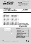
SPLIT-TYPE, HEAT PUMP AIR CONDITIONERS
September 2011
No. OCH480
REVISED EDITION-A
HFC
utilized
TECHNICAL & SERVICE MANUAL
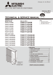
[Model name]
<Outdoor unit>
[Service Ref.]
MXZ-8B140VA
MXZ-8B160VA
MXZ-8B140YA
MXZ-8B160YA
MXZ-8B140VA
MXZ-8B160VA
MXZ-8B140YA
MXZ-8B160YA
R410A
Revision:
• Errors in "3.
SPECIFICATIONS"
have been corrected in
REVISED EDITION-A.
• Some descriptions have
been modified.
• Please void OCH480.
NOTE:
• This service manual
describes technical data
of outdoor unit. As for
indoor units and branch
box(OCH508), refer to its
service manual.
• RoHS compliant products
have <G> mark on the
spec name plate.
CONTENTS
1. SAFETY PRECAUTION ······································ 2
2. OVERVIEW OF UNITS ········································ 5
3. SPECIFICATIONS ············································· 12
4. DATA ·································································· 13
5. OUTLINES AND DIMENSIONS ························ 16
6. WIRING DIAGRAM············································ 17
7. NECESSARY CONDITIONS FOR SYSTEM CONSTRUCTION ··· 19
8. TROUBLESHOOTING ······································· 21
9. ELECTRICAL WIRING ······································ 54
10. WIRING SPECIFICATIONS. ······························ 56
11. SYSTEM CONTROL ·········································· 57
12. REFRIGERANT PIPING TASK·························· 59
13. DISASSEMBLY PROCEDURE ·························· 62
OUTDOOR UNIT
Model name
indication
INDOOR UNITS COMBINATION SHEETS
PARTS CATALOG (OCB480)
1
SAFETY PRECAUTION
1-1. ALWAYS OBSERVE FOR SAFETY
Before obtaining access to terminal, all supply
circuit must be disconnected.
1-2. CAUTIONS RELATED TO NEW REFRIGERANT
Cautions for units utilizing refrigerant R410A
Use new refrigerant pipes.
Make sure that the inside and outside of refrigerant piping is clean and it has no contaminants
such as sulfur, oxides, dirt, shaving particles, etc,
which are hazard to refrigerant cycle.
In addition, use pipes with specified thickness.
Contamination inside refrigerant piping can cause deterioration of refrigerant oil etc.
Store the piping to be used indoors during
installation, and both ends of the piping sealed
until just before brazing. (Leave elbow joints, etc.
in their packaging.)
Do not use refrigerant other than R410A.
If other refrigerant (R22 etc.) is used, chlorine in refrigerant can cause deterioration of refrigerant oil etc.
Use a vacuum pump with a reverse flow check
valve.
Vacuum pump oil may flow back into refrigerant cycle and
that can cause deterioration of refrigerant oil etc.
Use the following tools specifically designed for
use with R410A refrigerant.
The following tools are necessary to use R410A refrigerant.
Gauge manifold
Charge hose
Gas leak detector
Torque wrench
If dirt, dust or moisture enters into refrigerant cycle, that can
cause deterioration of refrigerant oil or malfunction of compressor.
The refrigerant oil applied to flare and flange
connections must be ester oil, ether oil or
alkylbenzene oil in a smalll amount.
If large amount of mineral oil enters, that can cause deterioration of refrigerant oil etc.
Tools for R410A
Flare tool
Size adjustment gauge
Vacuum pump adaptor
Electronic refrigerant
charging scale
Handle tools with care.
If dirt, dust or moisture enters into refrigerant cycle, that can
cause deterioration of refrigerant oil or malfunction of compressor.
Charge refrigerant from liquid phase of gas
cylinder.
Do not use a charging cylinder.
If the refrigerant is charged from gas phase, composition
change may occur in refrigerant and the efficiency will be
lowered.
If a charging cylinder is used, the composition of refrigerant will change and the efficiency will be lowered.
Use the specified refrigerant only.
Never use any refrigerant other than that specified.
Doing so may cause a burst, an explosion, or fire when the
unit is being used, serviced, or disposed of.
Correct refrigerant is specified in the manuals and on the
spec labels provided with our products.
We will not be held responsible for mechanical failure,
system malfunction, unit breakdown or accidents caused
by failure to follow the instructions.
Ventilate the room if refrigerant leaks during
operation. If refrigerant comes into contact with
a flame, poisonous gases will be released.
OCH480A
2
[1] Cautions for service
(1) Perform service after recovering the refrigerant left in unit completely.
(2) Do not release refrigerant in the air.
(3) After completing service, charge the cycle with specified amount of refrigerant.
(4) When performing service, install a filter drier simultaneously.
Be sure to use a filter drier for new refrigerant.
[2] Additional refrigerant charge
When charging directly from cylinder
· Check that cylinder for R410A on the market is syphon type.
· Charging should be performed with the cylinder of syphon stood vertically. (Refrigerant is charged from liquid phase.)
Unit
Gravimeter
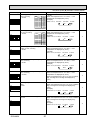
[3] Service tools
(1) Use the below service tools as exclusive tools for R410A refrigerant.
No.
Tool name
1
Gauge manifold
2
Charge hose
3
4
5
6
Electronic scale
Gas leak detector
Adaptor for reverse flow check
Refrigerant charge base
7
Refrigerant cylinder
8
Refrigerant recovery equipment
OCH480A
·
·
·
·
·
Specifications
Only for R410A
Use the existing fitting specifications. (UNF1/2)
Use high-tension side pressure of 5.3MPa·G or over.
Only for R410A
Use pressure performance of 5.09MPa·G or over.
· Use the detector for R134a, R407C or R410A.
· Attach on vacuum pump.
· Only for R410A
· Cylinder with syphon
3
· Top of cylinder (Pink)
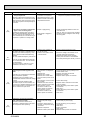
(2) Cautions for refrigerant piping work
New refrigerant R410A is adopted for replacement inverter series. Although the refrigerant piping work for R410A is same
as for R22, exclusive tools are necessary so as not to mix with different kind of refrigerant. Furthermore as the working
pressure of R410A is 1.6 times higher than that of R22, their sizes of flared sections and flare nuts are different.
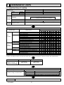
1 Thickness of pipes
Because the working pressure of R410A is higher compared to R22, be sure to use refrigerant piping with thickness
shown below. (Never use pipes of 0.7 mm or below.)
Diagram below: Piping diameter and thickness
Nominal
Thickness (mm)
Outside
dimensions(inch) diameter (mm)
R410A
R22
0.8
0.8
6.35
1/4
0.8
0.8
9.52
3/8
0.8
0.8
12.70
1/2
1.0
1.0
15.88
5/8
—
1.0
19.05
3/4
2 Dimensions of flare cutting and flare nut
The component molecules in HFC refrigerant are smaller compared to conventional refrigerants. In addition to that,
R410A is a refrigerant, which has higher risk of leakage because of its working pressure higher than that of other refrigerants. Therefore, to enhance airtightness and intensity, flare cutting dimension of copper pipe for R410A has been specified separately from the dimensions for other refrigerants as shown below. The dimension B of flare nut for R410A also
has partly been changed to increase intensity as shown below. Set copper pipe correctly referring to copper pipe flaring
dimensions for R410A below. For 1/2” and 5/8”, the dimension B changes.
Use torque wrench corresponding to each dimension.
Dimension A
Dimension B
Flare cutting dimensions
Nominal
Outside
dimensions(inch)
diameter
6.35
1/4
9.52
3/8
12.70
1/2
15.88
5/8
19.05
3/4
(mm)
Dimension A ( +0
-0.4 )
R410A
R22
9.0
9.1
13.0
13.2
16.2
16.6
19.4
19.7
—
23.3
Flare nut dimensions
Nominal
dimensions(inch)
1/4
3/8
1/2
5/8
3/4
Outside
diameter
6.35
9.52
12.70
15.88
19.05
(mm)
Dimension B
R410A
R22
17.0
17.0
22.0
22.0
24.0
26.0
27.0
29.0
—
36.0
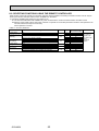
3 Tools for R410A (The following table shows whether conventional tools can be used or not.)
R410A tools
Can R22 tools be used? Can R407C tools be used?
Tool exclusive for R410A
Tool exclusive for R410A
Tool for HFC refrigerant
Tool exclusive for R410A
Tool exclusive for R410A
Ester oil and alkylbenzene
Ester oil:
Alkylbenzene oil: minimum amount
oil (minimum amount)
Prevent compressor malfunction Tool exclusive for R410A
Safety charger
when charging refrigerant by
spraying liquid refrigerant
Prevent gas from blowing out Tool exclusive for R410A
Charge valve
when detaching charge hose
Vacuum drying and air
Tools for other refrigerants can
Vacuum pump
(Usable if equipped
(Usable if equipped
with adopter for reverwith adopter for reverpurge
be used if equipped with adopse flow)
se flow)
ter for reverse flow check
Flaring work of piping
Tools for other refrigerants
Flare tool
(Usable by adjusting
(Usable by adjusting
can be used by adjusting
flaring dimension)
flaring dimension)
flaring dimension
Bend the pipes
Tools for other refrigerants can be used
Bender
Tools for other refrigerants can be used
Cut the pipes
Pipe cutter
Tools for other refrigerants can be used
Welder and nitrogen gas cylinder Weld the pipes
Tools for other refrigerants can be used
Refrigerant charging scale Refrigerant charge
Vacuum gauge or thermis- Check the degree of vacuum. (Vacuum Tools for other refrigerants
valve prevents back flow of oil and refri- can be used
tor vacuum gauge and
gerant to thermistor vacuum gauge)
vacuum valve
Refrigerant charge
Charging cylinder
Tool exclusive for R410A
: Prepare a new tool. (Use the new tool as the tool exclusive for R410A.)
: Tools for other refrigerants can be used under certain conditions.
: Tools for other refrigerants can be used.
Tools and materials
Gauge manifold
Charge hose
Gas leak detector
Refrigerant recovery equipment
Refrigerant cylinder
Applied oil
OCH480A
Use
Air purge, refrigerant charge
and operation check
Gas leak check
Refrigerant recovery
Refrigerant charge
Apply to flared section
4
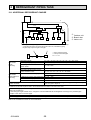
2
OVERVIEW OF UNITS
2-1. CONSTRUCTION OF SYSTEM
Outdoor unit
Rated
capacity (kW)
MXZ-8B140VA/160VA
MXZ-8B140YA/160YA
5HP
14.0
16.0
6HP
15.5
18.0
Cooling
Heating
Refrigerant
R410A
Type 15 ~ Type 100
CAUTION : The indoor unit which rated capability exceeds
Indoor unit Capacity
10.0kW (100 type) can NOT be connected.
that can be
connected Number of units
2 ~ 8 units
Total system wide capacity 21 ~ 132 % of outdoor unit capacity (3.0 kW ~ 18.5 kW) 19 ~ 130 % of outdoor unit capacity (3.0 kW ~ 20.2 kW)
Branch box
1 ~ 2 units
that can be Number of units
connected
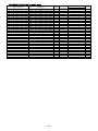
Connectable indoor unit lineup (Heat pump inverter type)
Model type
Capacity class (kW)
Model name
1.5 2.0 2.2 2.5 3.5 4.2 5.0 6.0 7.1 8.0 10.0*1
MSZ-FA25/35VA
MSZ-FB25/35/50VA(H)
MSZ-FD25/35/50VA
MSZ-GA22/25/35/50/60/71/80VA
Standard
Wall
MSZ-GB50VA
mounted
MSZ-GC22/25/35VA
MSZ-GC22/25/35/50/60/71NA
MSZ-GE22/25/35/42/50/60/71/80VA
MSZ-GE22/25/35/42/50/60/71NA
MSZ-EF22/25/35/42/50VE
MSZ-SF15/20VA
Compact
Low static pressure SEZ-KA/KC25/35/50/60/71VA
SEZ-KD25/35/50/60/71VA(L)
Middle static pressure PEAD-RP50/60/71EA.UK
Ceiling
PEAD-RP60/71GA.UK
concealed
PEAD-RP50/60/71JA(L).UK
High static pressure PEA-RP71EA/RP100EA2
MCFZ-GA35/50/60VA
2 by 2 type
SLZ-KA25/35/50VA(L)
4-way
PLA-RP35/50/60/71/100AA(.UK)/BA(.UK)
ceiling cassette Standard
PLA-RP71BA2.UK
PLA-RP100BA/BA3
MFZ-KA25/35/50VA
Floor standing
MLZ-KA25/35/50VA
1-way ceiling cassette
<NOTE> The lineup of a connectable indoor unit depends on a district/areas/country.
*1. When connectiing the indoor unit with the number 100, use the PAC-AK52YP-E Y-shape connection pipe (Optional part).
Deluxe
Branch box
Number of branches
Indoor unit that
can be connected
(
)
PAC-AK52BC
PAC-AK31BC
5 branches
(MAX. 5 units)
3 branches
(MAX. 3 units)
+ Max. 2 branch boxes can be connected to 1 outdoor unit.
2- branch pipe (joint) : Optional parts
In case of using 1- branch box
In case of using 2- branch boxes
Option
OCH480A
No need
Model name
Connection method
MSDD-50AR-E
flare
MSDD-50BR-E
brazing
+ According to the connection method, you can choose the favorite one.
Optional accessories of indoor units and outdoor units are available.
5
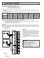
2-2. SYSTEM OUTLINE
The additional connection of the Branch Box together with employment of the compact trunk-looking outdoor unit can
successfully realizes a long distance piping for big houses. Equipped with a microprocessor, the Branch Box can translate the transmission signal of indoor units to achieve the optimum control.
2-2-1. System example
Indoor unit (Ceiling concealed type)
Indoor unit
(Wall mounted type)
Branch Box
Outdoor unit
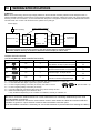
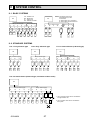
2-2-2. Method for identifying
■ Outdoor unit
Number of connectable indoor units (MAX.)
Model type
M X Z – 8 B 140 V A
Control and refrigerant
A : New A control and R410A
Power supply
V: Single phase 220/230/240V
Y: 3-Phase
380/400/450V
Multi type heat pump
inverter outdoor unit
Indicates equivalent to rated cooling capacity.
(0.1kW)
■ Branch box
Applicable refrigerant
A : R410A
Symbol of factory
P A C – A K 5 2 BC
Branch box (Controller)
Model type
(Indispensable)
Optional parts
OCH480A
50Hz
50Hz
Number of branches
5 : 5 branches
3 : 3 branches
6
2-3. TYPICAL COMBINATION EXAMPLE
Branch box is located INSIDE of condominium
Branch box
(Inside)
Installing branch box indoors
Only 1 piping is required between the outdoor and
indoor offering a fine external view.
■ System example of 5 indoor units
Branch box (5 branch type)
Master
bedroom
Living
Outdoor unit
SEZ-60
Dining
MSZ-35
Bedroom (1)
MSZ-35
Bedroom (2)
MSZ-25
MSZ-25
■ Verification
The rated capacity should be determined by observing the table below. The unit’s quantities are limited in 2 to 8 units.
For the next step, make sure that the selected total rated capacity is in a range as shown below.
The total indoor unit capacity should be within the outdoor units.
Combination of excessive indoor units and an outdoor unit may reduce the capacity of each indoor unit.
The rated indoor capacity is as the table below.
•MXZ-8B140 3.0 ~ 18.5 kW
•MXZ-8B160 3.0 ~ 20.2 kW
Example: MXZ-8B140
SEZ-60
MSZ-35
MSZ-35
MSZ-25
MSZ-25
= 6.0
+
= 3.5
+
= 3.5
+
= 2.5
+
= 2.5
Indoor unit type (capacity class)
Rated capacity (cooling) (kW)
OCH480A
Total rated capacity
18.0
15
1.5
18.5kW
20
2.0
22
2.2
25
2.5
7
35
3.5
42
4.2
50
5.0
60
6.0
71
7.1
80
8.0
100
10.0
2-4. INSTALLATION
2-4-1. Outdoor unit installation location
For best performance, select proper position.
● Avoid places where combustible gas may be generated or leak.
● Avoid direct sunlight or other sources of heat.
● Install sunshade to protect the outdoor unit if direct sunlight hits the unit.
● Install the outdoor unit with enough distance between neighbours as operation noise may disturb the neighbours.
● Avoid the position that the unit is covered by snow or snow blows directly against the air outlet. The snow block or blow will
reduce the airflow of the outdoor unit.
In the areas of heavy snow, special countermeasures must be taken at installation to protect the outdoor unit from malfunction caused by snow.
● Select a location permitting easy wiring and pipe access to the power source and indoor unit.
● Drain water must be drained freely during operation. Check for draining.
2-4-2. Ventilation and service space
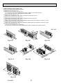
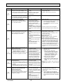
(1) Windy location installation
When installing the outdoor unit on a rooftop or other location unprotected from the wind, situate the air outlet of the unit so
that it is not directly exposed to strong winds. Strong wind entering the air outlet may impede the normal airflow and a malfunction may result.
The following shows 3 examples of precautions against strong winds.
● Face the air outlet towards the nearest available wall about 50 cm away from the wall. (Fig. 2-1)
● Install an optional air guide if the unit is installed in a location where strong winds from a typhoon, etc. may directly enter
the air outlet. (Fig. 2-2)
A Air guide
● Position the unit so that the air outlet blows perpendicularly to the seasonal wind direction, if possible. (Fig. 2-3)
B Wind direction
Fig. 2-1
Fig. 2-2
OCH480A
Fig. 2-3
8
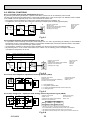
(2) When installing a single outdoor unit
Minimum dimensions are as follows, except for Max., meaning Maximum dimensions, indicated.
Refer to the figures for each case.
● Obstacles at rear only (Fig. 2-4)
● Obstacles at rear and above only (Fig. 2-5)
· Do not install the optional air outlet guides for upward airflow.
● Obstacles at rear and sides only (Fig. 2-6)
● Obstacles at front only (Fig. 2-7)
w When using an optional air outlet guide, the clearance is 500 mm or more.
● Obstacles at front and rear only (Fig. 2-8)
w When using an optional air outlet guide, the clearance is 500 mm or more.
● Obstacles at rear, sides, and above only (Fig. 2-9)
· Do not install the optional air outlet guides for upward airflow.
unit : mm
00
20
0
0
15
Fig. 2-4
1000
x. 5
Ma
Fig. 2-5
0
30
20
0
0
30
Fig. 2-6
00
.5
x
Ma
1500
0
15
00
10
00
10
25
0
25
0
Fig. 2-7
OCH480A
Fig. 2-8
9
Fig. 2-9
500
(3) When installing multiple outdoor units
Leave 10 mm space or more between the units.
● Obstacles at rear only (Fig. 2-10)
● Obstacles at rear and above only (Fig. 2-11)
• No more than 3 units must be installed side by side. In addition, leave space as shown.
• Do not install the optional air outlet guides for upward airflow.
● Obstacles at front only (Fig. 2-12)
w When using an optional air outlet guide, the clearance is 1000 mm or more.
● Obstacles at front and rear only (Fig. 2-13)
w When using an optional air outlet guide, the clearance is 500 mm or more.
● Single parallel unit arrangement (Fig. 2-14)
w When using an optional air outlet guide installed for upward airflow, the clearance is 1000 mm or more.
● Multiple parallel unit arrangement (Fig. 2-15)
w When using an optional air outlet guide installed for upward airflow, the clearance is 1500 mm or more.
● Stacked unit arrangement (Fig. 2-16)
• The units can be stacked up to 2 units high.
• No more than 2 stacked units must be installed side by side. In addition, leave space as shown.
unit : mm
0
. 30
1500
x
Ma
15
00
0
30
00
15
0
50
Fig. 2-10
Fig. 2-11
Fig. 2-12
0
15
0
50
00
20
0
50
00
15
00
10
0
60
00
30
0
60
00
15
Fig. 2-14
150
Fig. 2-13
15
00
0
80
Fig. 2-16
OCH480A
10
Fig. 2-15
2-5. SIMPLIFIED PIPING SYSTEM
Piping connection size
A
B
Liquid
(mm)
W9.52
Gas
(mm)
W15.88
The piping connection size differs according to the type and capacity of indoor units.
Match the piping connection size of branch box with indoor unit.
If the piping connection size of branch box does not match the piping connection size of
indoor unit, use optional different-diameter (deformed) joints to the branch box side.
(Connect deformed joint directly to the branch box side.)
For P100 indoor units, the individual Y-shape connection pipes use 2 ports on the branch box as shown below.
Branch box
Branch box
Port A
a
Port B
a
Y-shape connection pipe
b
Indoor unit
(P100)
Port A
a
Port B
a
Port C
Port C
a
Port D
Port D
a
Port E
Port E
Y-shape connection pipe
Y-shape connection pipe
b
Indoor unit
(P100)
b
Indoor unit
(P100)
To connect two P100 indoor units, use port A and port B, and
port C and port D on the branch box.
To connect a single P100 indoor unit, use port A and port
B on the branch box.
Flare connection employed. (No brazing!)
■ In case of using 1-branch box
Flare connection employed (No brazing)
Branch box
A
B
B
B
B
B
■ In case of using 2-branch boxes
2 branches pipe (joint)
: optional parts
A
A
Branch box #1
A
B
B
B
B
B
Branch box #2
■ Installation procedure (2 branch pipe (joint))
Refer to the installation manuals of MSDD-50AR-E and MSDD-50BR-E.
OCH480A
11
3
SPECIFICATIONS
MXZ-8B140VA MXZ-8B140YA
MXZ-8B160VA MXZ-8B160YA
kcal/h = kW % 860
Conversion formula: Btu/h = kW % 3412
CFM = m3/min % 35.31
Cooling
Heating
Standard performance
Service Ref.
Rated Cooling capacity
Rated power consumption +1
Operating current
+1
Operating power factor
+1
Starting current (Outdoor unit)
Rated Heating capacity
Rated power consumption +1
Operating current
+1
Operating power factor
+1
Starting current (Outdoor unit)
kW
kW
A
%
A
kW
kW
A
%
A
OUTDOOR UNIT
REFRIGERANT PIPING
:12.7mm
1/2 inch
:15.88mm
5/8 inch
MXZ-8B160VA
MXZ-8B140YA
MXZ-8B160YA
14.0
3.79
17.30/16.55/15.86
99.6
15.5
4.64
17.82/17.05/16.33
99.0
14.0
3.79
5.82/5.53/5.33
98.9
15.5
4.64
7.13/6.77/6.53
98.9
7
18.0
18.0
16.0
4.80
3.90
4.80
22.05/21.09/20.21
5.99/5.69/5.48
7.37/7.00/6.75
99.0
98.9
99.0
7
14
Please refer to "9.ELECTRICAL WIRING"
13
29.5
Single, 50Hz, 220/230/240V
3-phase, 50Hz, 380/400/415V
Munsall 3Y 7.8/1.1
Linear Expansion Valve (In branch box)
Hermetic
ANB33FNBMT
ANB33FDSMT
2.9
3.3
2.9
3.3
Line start
HP switch, LP switch, Discharge thermo
Plate fin coil
Propeller fan × 2
0.060+0.060
100(3,530)
106(3,742)
100(3,530)
106(3,742)
Reverse cycle
50
51
50
51
52
52
54
54
950(37-3/8)
330+30(13+1-3/16)
1,350(53-1/8)
129(284)
139(306)
R410A
8.5(18.7),40m
2.3(FV50S)
Φ9.52
Φ15.88
Flared
Flared
16.0
3.90
17.82/17.05/16.33
99.5
Breaker
Max. current (Outdoor unit only)
A
Power supply (phase, cycle, voltage)
External finish
Refrigerant control
Compressor
Model
Motor output
kW
Starter type
Protection devices
Crankcase heater
W
Heat exchanger
Fan
Fan (drive) % No.
Fan motor output
kW
Airflow
*/min (CFM)
Defrost method
Noise level
dB
Cooling
dB
Heating
Dimensions
mm (in.)
W
mm (in.)
D
mm (in.)
H
Weight
kg (lbs)
Refrigerant
Charge
kg (lbs)
Oil (Model)
L
Liquid
Pipe size O.D.
mm
Gas
mm
Indoor side
Connection method
Outdoor side
+1 Electrical data is only for outdoor unit.
Conversion formula
:6.35mm
:9.52mm
1/4 inch
3/8 inch
MXZ-8B140VA
14
:19.05mm
3/4 inch
Notes1. Rating Conditions (ISO T1)
Cooling : Indoor : D.B. 27°C (80°F), W.B. 19°C (66°F) Outdoor : D.B. 35°C (95°F), W.B. 24°C (75°F)
Heating : Indoor : D.B. 20°C (68°F)
Outdoor : D.B. 7°C (45°F), W.B. 6°C (43°F)
Refrigerant piping length (one way) : Main Piping (From outdoor unit to branch box) : 5m
Branch Piping (From branch box to each indoor units) : each 3m
2. Guaranteed operating range
Upper limit
Lower limit
Upper limit
Heating
Lower limit
Cooling
Indoor
Outdoor
M-series, S-series
P-series
D.B. 46°C
D.B. 35°C, W.B. 22.5°C D.B. 32°C, W.B. 23°C
D.B. –5°C
D.B. 19°C, W.B. 15°C D.B. 21°C, W.B. 15°C
D.B. 21°C, W.B. 15°C
D.B. 28°C
D.B. 27°C
D.B. 17°C
D.B. 20°C
D.B. –15°C, W.B. –15°C
3. Guaranteed voltage
MXZ-8B140/160VA: 198~264V, 50Hz
MXZ-8B140/160YA: 342~456V, 50Hz
4. Above data are based on the indicated voltage.
MXZ-8B140/160VA: Single, 50Hz, 220/230/240V
MXZ-8B140/160YA: 3-phase, 50Hz, 380/400/415V
5. Refer to the service manual of indoor unit for the indoor unit's specifications.
OCH480A
12
4
DATA
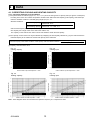
4-1. CORRECTING COOLING AND HEATING CAPACITY
4-1-1. Correcting Changes in Air Conditions
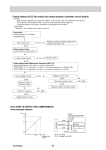
(1) The performance curve charts (Figure 4-1, 4-2, 4-3, 4-4) show the change ratio of capacity and input (power consumption)
according to the indoor and outdoor temperature condition when define the rated capacity (total capacity) and rated input
under the standard condition in standard piping length (5 m) as “1.0”.
• Standard conditions:
Indoor D.B. 27 °C / W.B. 19 °C
Rated cooling capacity
Outdoor D.B. 35 °C
Indoor D.B. 20 °C
Rated heating capacity
Outdoor D.B. 7 °C / W.B. 6 °C
• Use the rated capacity and rated power values given in the characteristics table for each indoor unit.
• The capacity is the single value on the side of the outdoor unit;
The capacity on the sides of each indoor unit must be added to obtain the total capacity.
(2) The capacity of each indoor unit may be obtained by multiplying the total capacity obtained in (1) by the ratio between the
individual capacity at the rated time and the total capacity at the rated time.
Individual capacity under stated conditions =Total capacity under the stated conditions o
Individual capacity at the rated time
Total capacity at the rated time
Fig. 4-1
Cooling capacity
Fig. 4-2
Cooling input
1.4
1.2
1.2
22
1
20
18
0.8
16
Cooling input ratio
Cooling capacity ratio
(3) Capacity correction factor curve
22 20
18
16
1.0
0.8
0.6
Indoor intake air wet-bulb temperature <:W.B.>
Indoor intake air wet-bulb temperature <:W.B.>
0.6
-5
0
5
10
15
20
25
30
35
40
46
0.4
-5
0
5
10
15
25
30
35
40
Outdoor intake air dry-bulb temperature <D.B. >
Outdoor intake air dry-bulb temperature <D.B. >
Fig. 4-3
Heating capacity
Fig. 4-4
Heating input
Indoor intake air dry-bulb temperature <:D.B.>
Outdoor intake air wet-bulb temperature <:W.B.>
Indoor intake air dry-bulb temperature <:D.B.>
Outdoor intake air wet-bulb temperature <:W.B.>
Note : These diagrams show the case where the operation frequency of a compressor is fixed.
OCH480A
20
13
46
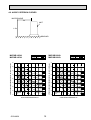
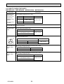
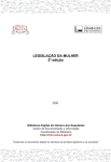
4-1-2. Correcting Capacity for Changes in the Length of Refrigerant Piping
To obtain the ratio (and the corrected piping length) of the outdoor units rated capacity and the total in-use indoor capacity, first
find the capacity ratio corresponding to the standard piping length from Fig. 4-5, Fig. 4-6 and then multiply by the capacity from
Fig. 4-1, 4-2, Fig. 4-3, 4-4 to obtain the actual capacity.
(1) Capacity correction factor
Fig. 4-5 Cooling capacity correction curve
MXZ-8B140VA, MXZ-8B140YA
20
40
60
80
0.95
1.00
Cooling Capacity (ratio) [%]
Cooling Capacity (ratio) [%]
1.00
MXZ-8B160VA, MXZ-8B160YA
Total rated capacity
of indoor units (kW)
0.90
2.2 (15.7%)
7.0 (50%)
10.5 (75%)
14.0 (100%)
18.5 (132%)
0.85
0.80
0.75
40
60
0.95
80
Total rated capacity
of indoor units (kW)
0.90
2.5(16%)
7.8 (50%)
0.85
11.6 (75%)
0.80
15.5 (100%)
20.2 (130%)
0.75
0.70
0.70
0.65
20
20
40
60
0.65
80
Corrected piping length (m)
20
40
60
80
Corrected piping length (m)
Fig. 4-6 Heating capacity correction curve
MXZ-8B140VA, MXZ-8B140YA, MXZ-8B160VA, MXZ-8B160YA
1
Heating
Capacity
(ratio) [%]
0.95
0.9
20
40
60
80
Corrected piping length (m)
(2) Method for Obtaining the Corrected Piping Length
Corrected piping length = (Actual piping length between outdoor unit and the farthest indoor unit) + (0.30 o number of bends in the piping) (m)
OCH480A
14
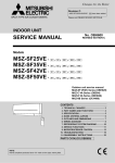
4-2. NOISE CRITERION CURVES
MICROPHONE
1m
UNIT
1.5m
GROUND
MXZ-8B140VA
MXZ-8B140YA
MODE SPL(dB)
COOLING
50
HEATING
52
LINE
MXZ-8B160VA
MXZ-8B160YA
80
70
NC-70
60
NC-60
50
NC-50
40
NC-40
30
NC-30
20
10
LINE
90
APPROXIMATE
THRESHOLD OF
HEARING FOR
CONTINUOUS
NOISE
63
125
NC-20
250
500
1000
2000
4000
8000
BAND CENTER FREQUENCIES, Hz
OCH480A
OCTAVE BAND SOUND PRESSURE LEVEL, dB (0 dB = 0.0002 μbar)
OCTAVE BAND SOUND PRESSURE LEVEL, dB (0 dB = 0.0002 μbar)
90
MODE SPL(dB)
COOLING
51
HEATING
54
80
70
NC-70
60
NC-60
50
NC-50
40
NC-40
30
NC-30
20
10
APPROXIMATE
THRESHOLD OF
HEARING FOR
CONTINUOUS
NOISE
63
125
NC-20
250
500
1000
2000
4000
BAND CENTER FREQUENCIES, Hz
15
8000
5
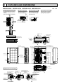
OUTLINES AND DIMENSIONS
MXZ-8B140VA MXZ-8B140YA MXZ-8B160VA MXZ-8B160YA
2 SERVICE SPACE
1 FREE SPACE (Around the unit)
Dimensions of space needed
for service access are
shown in the below diagram.
FREE
100
Over
The diagram below shows a basic
example.
Explanation of particular details are
given in the installation manuals etc.
unit : mm
3 FOUNDATION BOLTS
4 PIPING-WIRING DIRECTIONS
Please secure the unit firmly
with 4 foundation (M10) bolts.
(Bolts and washers must be
purchased locally.)
Piping and wiring connections
can be made from 4 directions:
front, right, rear and below.
10
Service space
Over 10
Over 1000
FOUNDATION
30
500
Over
Over
Over 10
Less than
<Foundation bolt height>
Over
500
Over 150
Rear Air Intake
175
···Refrigerant GAS pipe connection (FLARE):15.88(5/8 inch)
···Refrigerant LIQUID pipe connection (FLARE):9.52(3/8 inch)
Indication of STOP VALVE connection location
Handle for moving
Side Air Intake
417
56
28
42
56
950
Rear Air Intake
37
2-12×36 Oval holes
(Foundation Bolt M10) 70
Air Discharge
53
930
30
1079
MXZ-8B140YA/160YA
370
Side Air Intake
A
MXZ-8B140VA/160VA
2-U Shaped notched holes
(Foundation Bolt M10)
175
330
MODEL
600
Installation Feet
19
Example of Notes
322
(
Earth terminal
Terminal connection
Left ····Power supply wiring
Right ··Indoor/Outdoor wiring
)
Service panel
Handle for moving
Handle for moving
635
1350
Handle for moving
A
Handle for moving
1
Air Intake
1507
1423
371
2
23
Front piping cover
Rear piping cover
71
71
219
Bottom piping hole
(Knock-Out)
OCH480A
Rear trunking hole
(Knockout)
55
92
73 63
23
19
:92
27
:92
220
92
65
145
Power supply wiring hole
(2-:27Knockout)
55
40
63
65
23 27 92
73
55
73 63
27
92
23
Front piping hole
(Knockout)
75
30
Right trunking hole
(Knockout)
45
40
Rear piping hole
(Knockout)
16
145
145
)
:33
:92
Power supply wiring hole
(2-:27Knockout)
Right piping hole
(Knockout)
5ole(
in h
Dra
Power supply wiring hole
(2-:27Knockout)
Front trunking hole 40
45
(Knockout)
81
Piping Knockout Hole Details
6
WIRING DIAGRAM
MXZ-8B140VA MXZ-8B160VA
63H
TH7 TH6
C. B.
t°
NAME
t°
is the switch position.
3
1
TRANS
2
CN2
(WHT)
1
14
CNM
(WHT)
CN52C
(RED)
1
3
CN4
(WHT)
1 2
7
1
CNDC
(PNK)
2
CN31
LED3
3
7
F2
CNS
(WHT)
F1
1
2
3
4
F4
3
1 21S4 3
(GRN)
1 SV2 3
(BLU)
1 SV1
(GRY)
21S4
SV2
3
1
3
1
5
1 SS
(WHT)
SV1
2
1 2
CN4
(WHT)
3
1
3
1
CN2
(WHT)
P. B.
1
7
CN52C
3 (RED)
52C
52C
BLK
CNDC
(PNK)
3
WHT
1
CNAC2
(RED)
N2
E3
2
CB
1
P2
RED
IGBT
3
BLK
E2
3
F3
CNAC
(WHT)
1
SW7
SW6
SW1
SW8
1 3
63L
(RED)
SW9
5
SW2
1 3
63H
(YLW)
CNIT
(RED)
CN51 CNDM CN3S
(WHT) (WHT) (WHT)
CNF2
7 (WHT)
1
1
SW5
1 3
63HS
(WHT)
1 2
2 1
TH3 TH4
(WHT) (WHT)
SW4
4
1
TH7/6
(RED)
X51
MF2
MS
3~
t°
w1
CNF1
7 (WHT)
1
t°
63HS
X54
MF1
MS
3~
63L
X55
Terminal Block <Power Supply, Branch Box>
Motor for Compressor
Fan Motors
Solenoid Valve <Four-Way Valve>
High Pressure Switch
Low Pressure Switch
High Pressure Sensor
Solenoid Valve <Bypass Valve>
Thermistor <Outdoor Pipe>
Thermistor <Compressor>
Thermistor <Outdoor 2 - Phase Pipe>
Thermistor <Outdoor>
Reactor
Main Smoothing Capacitor
Capacitor
Power Circuit Board
Connection Terminal <U / V / W - Phase>
Connection Terminal <L / N - Phase>
Connection Terminal <CB>
Connection Terminal <DCL>
Power Module
Connection Terminal <Ground>
52C Relay
Controller Circuit Board
Switch <Forced Defrost, Defect History
Record Reset>
Switch <Self Diagnosis Switch>
SW2
Switch <Test Operation>
SW4
Switch <Function Switch>
SW5
SW6
Switch <Model Select>
SW7
Switch <Function Setup>
SW8
Switch <Function Setup>
SW9
Switch <Function Setup>
CN31
Connector
CN51
Connector <Connection for Option>
SS
Connector <Connection for Option>
CN3S
Connector <Connection for Option>
CNIT
Connector <Connection for Option>
CNDM
Connector <Connected for Option
(Contact Input)>
LED3
Light Emitting Diode
<Operation Inspection Indicators>
F1 ~ F4
Fuse <T6.3AL250V>
X51,X52,X54,X55 Relay
TH4
X52
SYMBOL
TB1
MC
MF1, MF2
21S4
63H
63L
63HS
SV1,SV2
TH3
TH4
TH6
TH7
DCL
CB
CY1,CY2
P. B.
U/V/W
LI / NI
P2,N2
DCL1,DCL2
IGBT
EI,E2,E3,E4
52C
C. B.
SW1
TH3
1
CNAC1
(WHT)
3
E4
BLK
BLK
RED
LI
NI
U
CY1
12345678
L
N
S1
S2
CY2
BRN
MC
ORN
ON
OFF
EI
YLW
160V
MS
3~
DCL
DCL1
BLU
140V
ON
OFF
V
DCL2
GRN / YLW
W
SW6
12345678
U
RED
MODEL
BLK
+1 MODEL SELECT
is the switch position.
WHT
W V
S3 TB1
BRANCH BOX
POWER SUPPLY
~/N
220/230/240V 50HZ
220V 60HZ
Operation / Inspection Display
LED on the controller board display the operation and inspection status as follows.
If LED does not light, it indicates that no power is supplied to the board:
Code
Details
(blinks)
Power turned on
Normal status
Faulty status
(blinking)
63L connector (red) is open.
63H connector (yellow) is open.
2 connectors (63H/63L) are open.
Branch box/outdoor communication error (Signal receiving error)(Outdoor unit)
Indoor/branch box communication error (Signal receiving error)(Branch box)
Branch box/outdoor communication error (Transmitting error)(Outdoor unit)
Indoor/branch box communication error (Transmitting error)(Branch box)
•Mis-Wiring of indoor-branch box / branch box-outdoor unit connecting wire.
•Too many indoor units / branch box are in the system.
Mis-wiring of indoor-branch box/branch box-outdoor unit connecting wire (converse wiring or disconnection)
Startup time over
Communication error except for outdoor unit
Combination errer, undefined error
Serial communication error
Operation status display,
such as C5. H7
F3
F5
F9
E8
E9
EA
Eb
Ec
E0 - E7
EE, EF
Ed
Details
Compressor temperature fault
Low-discharge superheating fault, Erroneous connection of refrigerant pipes or
the connecting wires
High pressure fault (63H operates)
Low pressure fault (63L operates)
Abnormality of power moduls
Compressor over current shutoff (Start up locked)
Current sensor fault (P. B.)
Compressor overcurrent shutoff fault
Compressor thermistor (TH4) open or short-circuit
Outdoor unit thermistors (TH3, TH6, TH7, and TH8), 63HS, and branch dox
thermistors open or short-circuit
Radiator panel temperature fault
Abnormality in outdoor fan motor
Voltage fault, current sensor fault
Forced compressor stop
(Overlap malfunction of drain pump in indoor unit
and linear expansion valve in branch box)
Code
U2
U7
U1
UL
U6
UF
UH
UP
U3
U4
U5
U8
U9
PA
Cautions when Servicing
●
●
WARNING:When the main supply is turned off, the voltage[340 V]in the main capacitor will drop to 20 V in approx. 2 minutes (input voltage : 240 V). when servicing, make sure that LED on the outdoor circuit board goes out,
and then wait for at least 1 minute.
Components other than the outdoor board may be faulty : Check and take corrective action, referring to the service manual. Do not replace the outdoor board without checking.
OCH480A
17
MXZ-8B140YA MXZ-8B160YA
63L
63H
TH7 TH6
+1 MODEL SELECT
is the switch position.
ON
OFF
t°
is the switch position.
CN4
(WHT)
1 2
7
1
CNDC
(PNK)
SW7
SW6
SW9
SW1
2
F4
3
4
1 21S4 3
(GRN)
1 SV2 3
(BLU)
1 SV1 3
(GRY)
1 SS
(WHT)
21S4
SV1
1
CN2
(WHT)
7
IGBT
TB-W
MC
BLK
W
WHT V MS
3~
RED U
TB-V
2 CN4
1 (WHT)
2 CN5
1 (RED)
RED
TB-N1
3
L1
POWER
SUPPLY
3N~
380/400/415V
50HZ
L2
L3
N
CNCT
(RED) 1
3
21
CNAC2
3 (RED)
LI1
LO1 RED
WHT
LI2
LO2 WHT
LI3
LO3
BLK
NI
NO
BLU
BLU
RED
L1-OU
L1-A2
WHT
RED
L2-A2
N-IN
ACL1
RED
BLK
CONV. B.
BLK CK-OU
1
CK
BLU
CB2
2
CNAC1
(WHT) 1
WHT
3
N. F.
TB1
L2-OU
BLK
WHT
RED
CB1
BRN
S2
TB-C1
L1-A1
TB-P2
BLK
YLW
RED
ORN
S1
L3-OU
RS
CY2
CY1
TB2
S3
BLK
WHT
TB-L1
X52A
RED
BRANCH
BOX
TB-U
TB-L3
TB-L2
L1-IN
2
5
7
3
1
3
CN7
(WHT)
2
3
1
RED
P. B.
SV2
3
1
BLK
3
1
L3-A2
1
2
X51
3
F3
CNAC
(WHT)
1
F1
X54
F2
X55
7
CNS
(WHT)
SW2
CN31
LED3
RED
CN2
(WHT)
1
14
CNM
(WHT)
CN51 CNDM CN3S
(WHT) (WHT) (WHT)
TRANS
1
CN7
(WHT)
3
2
1 3
63L
(RED)
1 3
63H
(YLW)
CNIT
(RED)
5
SW8
CNF2
7 (WHT)
1
1
SW5
1 3
63HS
(WHT)
1 2
2 1
TH3 TH4
(WHT) (WHT)
ACL2
ACL3
GRN/YLW
12345678
12345678
BLK
GD1
GD3
CNDC 1
(PNK)
2
3
3
1 CNL
(BLU)
WHT
160Y
t°
+1
4
1
TH7/6
(RED)
BRN
ON
OFF
t°
63HS
SW4
MF2
MS
3~
SW6
140Y
t°
CNF1
7 (WHT)
1
TH4
BLK
MODEL
C. B.
MF1
MS
3~
TH3
X52
NAME
Terminal Block <Power Supply>
Terminal Block <Branch Box>
Motor for Compressor
Fan Motors
Solenoid Valve <Four-Way Valve>
High Pressure Switch
Low Pressure Switch
High Pressure Sensor
Solenoid Valve <Bypass Valve>
Thermistor <Outdoor Pipe>
Thermistor <Compressor>
Thermistor <Outdoor 2 - Phase Pipe>
Thermistor <Outdoor>
Reactor
Main Smoothing Capacitor
Capacitor
Rush Current Protect Resistor
Capacitor
Power Circuit Board
Connection Terminal <U / V / W - Phase>
Connection Terminal <L1/L2/L3-Power Supply>
Connection Terminal
Connection Terminal
Connection Terminal
Power Module
52C Relay
Noise Filter Circuit Board
Connection Terminal <L1/L2/L3/N-Power Supply>
Connection Terminal <L1/L2/L3/N-Power Supply>
Connection Terminal <Ground>
Controller Circuit Board
Connection Terminal <L1-Power Supply>
Connection Terminal <L1-Power Supply>
Connection Terminal <L2-Power Supply>
Connection Terminal <L3-Power Supply>
Connection Terminal <N-Power Supply>
Connection Terminal <CK>
Controller Circuit Board
Switch <Forced Defrost, Defect History
Record Reset>
Switch <Self Diagnosis Switch>
SW2
Switch <Test Operation>
SW4
Switch <Function Switch>
SW5
SW6
Switch <Model Select>
SW7
Switch <Function Setup>
Switch <Function Setup>
SW8
Switch <Function Setup>
SW9
CN31
Connector
CN51
Connector <Connection for Option>
SS
Connector <Connection for Option>
Connector <Connection for Option>
CN3S
Connector <Connection for Option>
CNIT
CNDM
Connector <Connected for Option
(Contact Input)>
LED3
Light Emitting Diode
<Operation Inspection Indicators>
Fuse <T6.3AL250V>
F1 ~ F4
X51,X52,X54,X55 Relay
SYMBOL
TB1
TB2
MC
MF1, MF2
21S4
63H
63L
63HS
SV1,SV2
TH3
TH4
TH6
TH7
ACL1~ACL4
CB1, CB2
CK
RS
CY1,CY2
P. B.
TB-U/V/W
TB-L1/L2/L3
TB-P2
TB-C1
TB-N1
IGBT
X52A
N. F.
LI1/LI2/LI3/NI
LO1/LO2/LO3/NO
GD1, GD3
CONV.B.
L1-A1 / IN
L1-A2 / OU
L2-A2 / OU
L3-A2 / OU
N-IN
CK-OU
C. B.
SW1
ACL4
Operation / Inspection Display
LED on the controller board display the operation and inspection status as follows.
If LED does not light, it indicates that no power is supplied to the board:
Code
Details
Normal status
Faulty status
(blinking)
Details
Compressor temperature fault
Low-discharge superheating fault, Erroneous connection of refrigerant pipes or
the connecting wires
High pressure fault (63H operates)
Low pressure fault (63L operates)
Abnormality of power moduls
Compressor over current shutoff (Start up locked)
Current sensor fault (P. B.)
Compressor overcurrent shutoff fault
Compressor thermistor (TH4) open or short-circuit
Outdoor unit thermistors (TH3, TH6, TH7), 63HS, and branch dox
thermistors open or short-circuit
Radiator panel temperature fault
Abnormality in outdoor fan motor
Voltage fault, current sensor fault
Forced compressor stop
(Overlap malfunction of drain pump in indoor unit
and linear expansion valve in branch box)
(blinks)
Power turned on
63L connector (red) is open.
63H connector (yellow) is open.
2 connectors (63H/63L) are open.
Branch box/outdoor communication error (Signal receiving error)(Outdoor unit)
Indoor/branch box communication error (Signal receiving error)(Branch box)
Branch box/outdoor communication error (Transmitting error)(Outdoor unit)
Indoor/branch box communication error (Transmitting error)(Branch box)
•Mis-Wiring of indoor-branch box / branch box-outdoor unit connecting wire.
•Too many indoor units / branch box are in the system.
Mis-wiring of indoor-branch box/branch box-outdoor unit connecting wire (converse wiring or disconnection)
Startup time over
Communication error except for outdoor unit
Combination errer, undefined error
Serial communication error
Operation status display,
such as C5. H7
F3
F5
F9
E8
E9
EA
Eb
Ec
E0 - E7
EE, EF
Ed
Code
U2
U7
U1
UL
U6
UF
UH
UP
U3
U4
U5
U8
U9
PA
Cautions when Servicing
●
●
WARNING:When the main supply is turned off, the voltage[540 V]in the main capacitor will drop to 20 V in approx.5 minutes (input voltage : 380 V). when servicing, make sure that LED on the outdoor circuit board goes out,
and then wait for at least 5 minute.
Components other than the outdoor board may be faulty : Check and take corrective action, referring to the service manual.
Do not replace the outdoor board without checking.
OCH480A
18
7
NECESSARY CONDITIONS FOR SYSTEM CONSTRUCTION
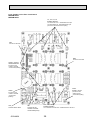
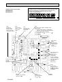
REFRIGERANT SYSTEM DIAGRAM
MXZ-8B140VA MXZ-8B140YA MXZ-8B160VA MXZ-8B160YA
Condenser / evaporator
temperature thermistor
(TH5 or RT12)
Room temperature
thermistor (TH1 or RT11)
Service port
Strainer
#50
Capillary
tube1
Ball valve
Check valve
(Low Pressure)
LEV A~E
(Linear expansion valve)
Strainer
#100
Outdoor unit
Capillary
tube3
Branch box
Distributor
with Strainer
Oil separator
Thermistor TH4
(Compressor temperature)
Thermistor TH8
(Fin temperature)
Accumulator
Service port
Compressor
Refrigerant flow in cooling
Refrigerant flow in heating
Strainer
#100
Branch box
MXZ-8B140VA
MXZ-8B160VA
MXZ-8B140YA
MXZ-8B160YA
High
pressure
switch
63H
Low
pressure
switch
63L
Stop valve
Indoor units
Thermistor TH3
(Pipe temperature : liquid)
Capillary
tube2
Strainer
#100
Strainer
#100
Thermistor TH6
(Pipe temperature : condenser)
Strainer
#100
Thermistor (TH-A~E)
(Gas pipe temperature)
Capillary
tube4
Thermistor TH7
(Outdoor temperature)
Bypass valve (SV1)
E
D
C
B
A
Pipe temperature
thermistor / liquid
(TH2 or RT13)
Check valve
(High Pressure)
Bypass valve(SV2)
4-way valve
High pressure sensor
discharge pressure sensor
63HS
Outdoor unit
Capillary tube 1
(For return of oil
from oil separator)
Capillary tube 2
(For SV2)
:2.5 % :0.8 % L1000
:4 % :2.4 % L250
Capillary tube 3
ahead of LEV
(in cooling mode)
unit : mm
Capillary tube 4
behind LEV
(in cooling mode)
PAC-AK52BC
(:4 % :2.4 % L140) % 5 (:4 % :2.2 % L130) % 5
PAC-AK31BC
(:4 % :2.4 % L140) % 3 (:4 % :2.2 % L130) % 3
Piping connection size
B
A
Liquid (mm)
{9.52
Gas (mm)
{15.88
The pipe connection size differs according to the type and capacity of indoor units.
Match the piping connection size of branch box with indoor unit.
If the piping connection size of branch box does not match the piping connection size
of indoor unit, use optional different-diameter (deformed) joints to the branch box side.
(Connect deformed joint directly to the branch box side.)
■ In case of using 1-branch box
Flare connection employed (No brazing)
Branch box
A
B
B
B
B
B
■ In case of using 2-branch boxes
2 branches pipe (joint)
: optional parts
A
A
Branch box #1
■ installation procedure (2 branch pipe (joint))
Refer to the installation manuals of
MSDD-50AR-E and MSDD-50BR-E.
A
B
OCH480A
B
B
Branch box #2
19
B
B
■ Pipe size (Branch box-Indoor unit) *Case of M series or S series Indoor unit
Indoor unit type (kW)
Liquid
Pipe size (mm)
Gas
15
:6.35
:9.52
35
:6.35
:9.52
25
:6.35
:9.52
22
:6.35
:9.52
20
:6.35
:9.52
60
:6.35
:15.88 +
50
:6.35
:12.7
42
:6.35
:9.52
80
:9.52
:15.88
71
:9.52
:15.88
When using 60 type indoor unit of MEXZ series, use the flare nut in the indoor unit accessory for the gas side connecting of
indoor unit.
Do not use the flare nut (gas side) attached to the indoor unit. If it is used, a gas leakage or even a pipe extraction may occur.
■ Pipe size (Branch box-Indoor unit) *Case of P series Indoor unit
Indoor unit type
Pipe size
(mm)
(kW)
Liquid
Gas
50
:6.35
:12.7
35
:6.35
:12.7
60
:9.52
:15.88
71
:9.52
:15.88
100+
:9.52
:15.88
When using 35, 50 type indoor unit of P series, use the flare nut (for R410A) attached to the indoor unit.
Do not use the flare nut (for R407C) in the indoor unit accessory. If it is used, a gas leakage or even a pipe extraction may occur.
w For the connection of P100 indoor unit(s), use the refrigerant pipes specified in the table below.
Distance between
branch box and
Y-shape connection
pipe (=a)
1 to 10 [m]
10 [m] or more
Branch box
Port A
a
Port B
a
Y-shape connection pipe
Port C
b
Indoor unit
(P100)
<Length limit>
1[m]≤a
a+b≤15[m]
Port D
Liquid
Gas
a
b
a
b
6.35
6.35
9.52
9.52
9.52
12.7 1
15.88
15.88
1 To connect a 12.7 gas pipe, use a joint pipe (MAC-A454JP)
Port E
(1) Valve size for outdoor unit
For liquid
For gas
:9.52 mm
:15.88 mm
(2) Valve size for branch unit
+
+
+
UNIT
Liquid pipe
Gas pipe
UNIT
Liquid pipe
Gas pipe
UNIT
Liquid pipe
Gas pipe
UNIT
Liquid pipe
Gas pipe
Liquid pipe
Gas pipe
+ 3- branch type is only for , , and unit.
UNIT
:6.35 mm
:9.52 mm
:6.35 mm
:9.52 mm
:6.35 mm
:9.52 mm
:6.35 mm
:9.52 mm
:6.35 mm
:12.7 mm
Different-diameter joint (optional parts) (Fig.7-1)
Model name
MAC-A454JP
MAC-A455JP
MAC-A456JP
PAC-493PI
PAC-SG76RJ-E
Connected pipes diameter Diameter A Diameter B
mm
mm
mm
W12.7
W9.52
W9.52 © W12.7
W9.52
W12.7
W12.7 © W9.52
W15.88
W12.7
W12.7 © W15.88
W9.52
W6.35
W6.35 © W9.52
W15.88
W9.52
W9.52 © W15.88
A
B
Fig.7-1
Conversion formula
1/4 inch
:6.35mm
3/8 inch
:9.52mm
1/2 inch
:12.7mm
5/8 inch :15.88mm
3/4 inch :19.05mm
Y-shape connection pipe for 100 type indoor unit (optional parts)
(Fig.7-2)
Connected pipe diameter Diameter A Diameter B
mm
mm
mm
Liquid
ø6.35
ø9.52
ø6.35 → ø9.52
PAC-AK52YP-E
Gas
ø9.52
ø15.88
ø9.52 → ø15.88
A
Model name
OCH480A
20
Fig.7-2
B
8
TROUBLESHOOTING
8-1. TROUBLESHOOTING
<Error code display by self-diagnosis and actions to be taken for service (summary)>
Present and past error codes are logged and displayed on the wired remote controller and control board of outdoor unit.
Actions to be taken for service, which depends on whether or not the trouble is reoccurring at service, are summarized in the
table below. Check the contents below before investigating details.
Unit conditions at service
Actions to be taken for service (summary)
Error code
Judge what is wrong and take a corrective action according
to “8-3. SELF-DIAGNOSIS ACTION TABLE”.
Displayed
The trouble is reoccurring.
Not displayed
Conduct trouble shooting and ascertain the cause of the
trouble according to “8-4. TROUBLESHOOTING
BY INFERIOR PHENOMENA”.
Logged
Consider the temporary defects such as the work of
protection devices in the refrigerant circuit including
compressor, poor connection of wiring, noise and etc.
Re-check the symptom, and check the installation
environment, refrigerant amount, weather when the
trouble occurred, matters related to wiring and etc.
Reset error code logs and restart the unit after finishing
service.
There is no abnormality concerning of parts such as
electrical component, controller board, remote controller
and etc.
Not logged
Re-check the abnormal symptom.
Conduct trouble shooting and ascertain the cause of the
trouble according to “8-4. TROUBLESHOOTING
BY INFERIOR PHENOMENA”.
Continue to operate unit for the time being if the cause
is not ascertained.
There is no abnormality concerning of parts such as
electrical component, controller board, remote controller
and etc.
The trouble is not reoccurring.
OCH480A
21
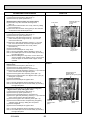
8-2. CHECK POINTS FOR TEST RUN
8-2-1. Before test run
● Turn on the main power switch more than 12 hours before starting operation. Starting operation just after turning on the
power switch can severely damage the internal parts. Keep the main power switch turned on during the operation season.
● After completing installation and the wiring and piping of the indoor and outdoor units, check for refrigerant leakage, looseness in the power supply or control wiring, wrong polarity, and no disconnection of one phase in the supply.
● Use a 500-volt M-ohm tester to check that the resistance between the power supply terminals and ground is at least 1 M".
● Do not carry out this test on the control wiring (low voltage circuit) terminals.
Warning: Do not use the air conditioner if the insulation resistance is less than 1 M".
Insulation resistance
After installation or after the power source to the unit has been cut for an extended period, the insulation resistance will drop
below 1 M" due to refrigerant accumulating in the compressor. This is not a malfunction. Perform the following procedures.
1. Remove the wires from the compressor and measure the insulation resistance of the compressor.
2. If the insulation resistance is below 1 M", the compressor is faulty or the resistance dropped due to the accumulation of
refrigerant in the compressor.
3. After connecting the wires to the compressor, the compressor will start to warm up after power is supplied. After supplying
power for the times indicated below, measure the insulation resistance again.
• The insulation resistance drops due to accumulation of refrigerant in the compressor. The resistance will rise above 1M"
after the compressor is warmed up for 4 hours. (The time necessary to warm up the compressor varies according to
atmospheric conditions and refrigerant accumulation.)
• To operate the compressor with refrigerant accumulated in the compressor, the compressor must be warmed up at least 12
hours to prevent breakdown.
4. If the insulation resistance rises above 1 M", the compressor is not faulty.
Caution:
• The compressor will not operate unless the power supply phase connection is correct.
• Turn on the power at least 12 hours before starting operation.
Staring operation immediately after turning on the main power switch can result in severe damage to internal parts.
Keep the power switch turned on during the operational season.
● The followings must be checked as well.
• The outdoor unit is not faulty. LED on the control board of the outdoor unit flashes when the outdoor unit is faulty.
• Both the gas and liquid stop valves are completely open.
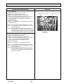
8-2-2. Test run
(1) Using remote controller
Refer to the indoor unit installation manual.
• Be sure to perform the test run for each indoor unit. Make sure each indoor unit operates properly following the installation
manual attached to the unit.
• If you perform the test run for all indoor units at once, you cannot detect any erroneous connection, if any, of the refrigerant
pipes and the connecting wires.
* The compressor operation is not available for 3 minutes at least after the power is supplied.
• The compressor can emit noise just after turn on the power supply or in case of low outside air temperature.
About the restart protective mechanism
Once the compressor stops, the restart preventive device operates so the compressor will not operate for 3 minutes to protect
the air conditioner.
OCH480A
22
(2) Using SW4 in outdoor unit
In case of the test run from outdoor unit, all indoor units operate. Therefore, you cannot detect any erroneous connection of refrigerant pipes and the connecting wires. If it aims at detection of any erroneous connection, be sure to
carry out the test run from remote controller with reference to "(1) Using remote controller."
SW4-1
SW4-2
SW4-1
SW4-2
ON
OFF
ON
ON
Cooling operation
Heating operation
+ After performing the test run, set SW4-1 to OFF.
• A few seconds after the compressor starts, a clanging noise may be heard from the inside of the outdoor unit. The noise is
coming from the check valve due to the small difference in pressure in the pipes. The unit is not faulty.
The test run operation mode cannot be changed by DIP switch SW4-2 during the test run. To change the test run
operation mode during the test run, stop the test run by DIP switch SW4-1. After changing the test run operation
mode, resume the test run by switch SW4-1.
When a test run is started by “Using SW4 in outdoor unit”, even if it carries out stop instructions by
remote controller, outdoor unit does not stop. A test run is not ended.
In this case, please set SW4 in outdoor unit to off.
• After power is supplied or after an operation stop for a while, a small clicking noise may be heard from the inside
of the branch box. The electronic expansion valve is opening and closing. The unit is not faulty.
NOTE: Be sure to wait at least 3 minutes after turning on the power supply before setting SW4-1 and SW4-2.
If the DIP switches are set before 3 minutes have elapsed, the test run may not start.
8-2-3. Test run by outdoor unit SW4
The setting of test run (ON/OFF) and its operation mode (cooling/heating) can be set by SW4 on the controller board of outdoor unit.
1 Set operation mode (cooling or heating) by SW4-2.
2 Start test run by setting SW4-1 to ON ( ) with the indicated operation mode of SW4-2.
SW4 (Initial setting)
3 Finish test run by setting SW4-1 to OFF ( ).
• Operation mode cannot be changed by SW4-2 during test run.
Stop
ON
Stop test run to change operation mode by SW4-1, and restart test run by SW4-1 after
Cooling
the mode is changed.
Operation
• Test run automatically stops 2 hours later by 2-hour OFF timer function.
Heating
1
2
• Test run can be performed by the remote controller.
• The remote controller display of test run by outdoor unit is the same as that of test run by
remote controller.
• If test run is set with the outdoor unit, the test run is performed for all indoor units.
• The remote controller operation becomes unavailable once the test run is set with the outdoor unit.
During the test run set with the outdoor unit, operation on/off or operation mode change cannot be performed by the remote
controller, and the operation relating to the test run which is made with the outdoor unit will be prior to any other commands
from the remote controller. Set the SW4-1 to OFF ( ) to finish test run.
Emergency operation is not available for this model.
OCH480A
23
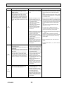
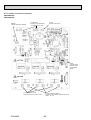
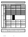
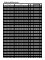
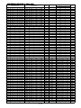
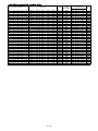
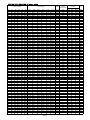
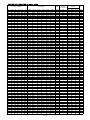
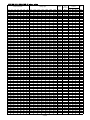
8-3. SELF-DIAGNOSIS ACTION TABLE
<Abnormalities detected when the power is put on>
Error Code
Abnormal point and detection method
(Note 1) Refer to indoor unit section for code P and code E.
Case
Judgment and action
1 No voltage is supplied to termi- 1 Check following items.
a) Power supply breaker
nal block (TB1) of outdoor unit.
b) Connection of power supply terminal
a) Power supply breaker is
block.
turned off.
(TB1)
b) Contact failure or disconnecc) Connection of power supply terminal
tion of power supply terminal
block.
c) Open phase (L or N phase)
(TB1)
2 Electric power is not charged to 2 Check following items.
a) Connection of power supply terminal
power supply terminal of outblock.
door power circuit board.
(TB1)
a) Contact failure of power
b) Connection of terminal on outdoor power
supply terminal
circuit board.
b) Open phase on the outdoor
Disconnection of connector SC-R or
power circuit board
SC-S
Disconnection of connector
Refer to 8-7.
SC-R or SC-S
None
—
3 Electric power is not supplied
to outdoor controller circuit
board.
a) Disconnection of connector
(CNDC)
3 Check connection of the connector (CNDC)
on the outdoor controller circuit board.
Check connection of the connector, CNDC
on the outdoor power circuit board.
Refer to 8-7.
4 Disconnection of reactor (DCL) 4 Check connection of reactor. (DCL)
Check connection of “L1” and “L2”
on the active filter module. (ACTM)
5 Disconnection of outdoor noise 5 a) Check connection of outdoor noise filter
circuit board.
filter circuit board or parts failb) Replace outdoor noise filter circuit board.
ure in outdoor noise filter circuit
Refer to 8-7.
board
6 Defective outdoor power circuit 6 Replace outdoor power circuit board.
board
7 Replace controller board (When items
7 Defective outdoor controller
above are checked but the units cannot be
circuit board
repaired.)
F3
(5202)
63L connector open
1 Disconnection or contact failure 1 Check connection of 63L connector on
Abnormal if 63L connector circuit is open
of 63L connector on outdoor
outdoor controller circuit board.
for 3 minutes continuously after power supcontroller circuit board
Refer to 8-7.
ply
2 Disconnection or contact failure 2 Check the 63L side of connecting wire.
63L: Low-pressure switch
of 63L
3 63L is operating due to refriger- 3 Check refrigerant pressure.
ant leakage or defective parts.
Charge additional refrigerant.
4 Defective outdoor controller
Check continuity by tester.
circuit board
Replace the parts if the parts are defective.
4 Replace outdoor controller circuit board.
F5
(5201)
63H connector open
1 Disconnection or contact failure
Abnormal if 63H connector circuit is open
of 63H connector on outdoor
for 3 minutes continuously after power supcontroller circuit board
ply
2 Disconnection or contact failure
63H: High-pressure switch
of 63H
3 63H is operating due to defective parts.
4 Defective outdoor controller
circuit board
1 Check connection of 63H connector on
outdoor controller circuit board.
Refer to 8-7.
2 Check the 63H side of connecting wire.
F9
(4119)
2 connector open
1 Disconnection or contact failure
Abnormal if both 63H and 63L connector
of connector (63H, 63L) on
circuits are open for 3 minutes continuously
outdoor controller circuit board.
after power supply
2 Disconnection or contact failure
of 63H, 63L
63H: High-pressure switch
3 63H and 63L are operating due
63L: Low-pressure switch
to defective parts.
4 Defective outdoor controller
board
1 Check connection of connector (63H,63L) on
outdoor controller circuit board.
Refer to 8-7.
2 Check the 63H and 63L side of connecting
wire.
3 Check continuity by tester.
Replace the parts if the parts are defective.
4 Replace outdoor controller circuit board.
OCH480A
24
3 Check continuity by tester.
Replace the parts if the parts are defective.
4 Replace outdoor controller circuit board.
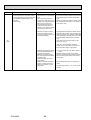
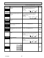
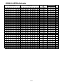
Error Code
EA
(6844)
Case
Abnormal point and detection method
Judgment and action
Indoor–branch box/branch box–outdoor 1 Contact failure or miswiring of 1 Check disconnection or looseness or polarunit connector miswiring, excessive
indoor/outdoor unit connecting
ity of indoor–branch box/branch box–outdoor
number of units
wire
unit connecting wire of indoor and outdoor
Outdoor/branch box controller circuit board
units.
can automatically check the number of
Before connecting P100 indoor unit(s), check
connected indoor units. Abnormal if the
the requirements described in "9-2. Wiring to
number cannot be checked automatically
P100 indoor units".
due to miswiring of indoor– branch box/
branch box–outdoor unit connecting wire
2 Diameter or length of indoor–
2 Check diameter and length of indoor–branch
and etc. after power is turned on for 4 minbranch box/branch box–outbox/branch box–outdoor unit connecting wire.
utes.
door unit connecting wire is out
Total wiring length: 55 m (outdoor–branch box)
of specified capacity.
(including wiring connecting each branch box
There are 9 or more indoor
unit and between branch box and outdoor
units in the system.
unit)
There are 3 or more branch
Also check if the connection order of flat
boxes in the system.
cable is S1, S2, S3.
More than two P100 indoor
units are connected to the
If the error “EA” is detected, check the
branch box.
number of the indoor units, the branch box
and P100 indoor unit(s) in the system.
3 Defective transmitting receiving 3~5 Turn the power off once, and on again to
circuit of outdoor/branch box
check.
controller circuit board
Replace outdoor controller circuit board,
branch box controller board, indoor controller
4 Defective transmitting receiving circuit of branch box/indoor
board or indoor power board if abnormality
controller board
occurs again.
5 Defective branch box/indoor
power board
6 Noise has entered into power
6 Check transmission path, and remove the
supply or indoor–branch box/
cause.
branch box–outdoor unit connecting wire.
w The descriptions above, 1-6, are for EA, Eb
and EC.
Eb
(6845)
Miswiring of indoor–branch box/branch
box–outdoor unit
connecting wire (converse wiring or disconnection)
Outdoor/branch box controller circuit board
can automatically set the unit number of
indoor units.
Abnormal if the indoor unit number can
not be set within 4 minutes after power
on because of miswiring (converse wiring
or disconnection) of indoor–branch box/
branch box–outdoor unit connecting wire.
1 Contact failure or miswiring of
indoor–branch box/branch box
–outdoor unit connecting wire
2 Diameter or length of indoor–
branch box/branch box–outdoor unit connecting wire is out
of specified capacity.
4 Defective transmitting receiving
circuit of outdoor/branch box
controller circuit board
5 Defective transmitting receiving circuit of indoor/branch box
controller board
6 Defective indoor/branch box
power board
7 Noise has entered into power
supply or indoor–branch box/
branch box–outdoor unit connecting wire.
Start-up time over
The unit cannot finish start-up process
within 4 minutes after power on.
1 Contact failure of indoor–
branch box/branch box–outdoor
unit connecting wire
2 Diameter or length of indoor–
branch box/branch box–outdoor
unit connecting wire is
out of specified capacity.
3 Noise has entered into power
supply or indoor–branch box/
branch box–outdoor unit connecting wire.
EC
(6846)
OCH480A
25
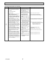
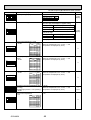
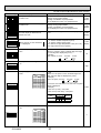
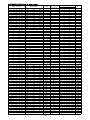
Error Code
Abnormal point and detection method
Faulty connection of LEV
For the connection of P100 indoor unit(s),
the connecting wire(s) must be connected
to the specified terminal block(s) in the
branch box.
Incorrect wiring
Case
Judgment and action
1 Contact failure or miswiring of 1 Check disconnection or looseness or polarindoor/outdoor unit connecting
ity of indoor–branch box/branch box–outdoor
wire
unit connecting wire of indoor and outdoor
The connecting wire(s) from
units.
P100 indoor unit(s) are not conBefore connecting P100 indoor unit(s), check
nected to the specified terminal
the requirements described in "9-2. Wiring to
block(s) in the branch box.
P100 indoor units".
The connecting wire(s) from
P100 indoor unit(s) are connected to an incorrect terminal
block(s) in the branch box.
2 Diameter or length of indoor–
2 Check diameter and length of indoor–branch
branch box/branch box–outbox/branch box–outdoor unit connecting wire.
door unit connecting wire is out
Total wiring length: 55 m (outdoor–branch box)
of specified capacity.
(including wiring connecting each branch box
unit and between branch box and outdoor
unit)
Also check if the connection order of flat
cable is S1, S2, S3.
EE
(7130)
If the error “EA” is detected, check the
number of the indoor units, the branch box
and P100 indoor unit(s) in the system.
3 Defective transmitting receiving 3~5 Turn the power off once, and on again to
circuit of outdoor/branch box
check.
controller circuit board
Replace outdoor controller circuit board,
branch box controller board, indoor controller
4 Defective transmitting receiving circuit of branch box/indoor
board or indoor power board if abnormality
controller board
occurs again.
5 Defective branch box/indoor
power board
6 Noise has entered into power
6 Check transmission path, and remove the
supply or indoor–branch box/
cause.
branch box–outdoor unit connecting wire.
w The descriptions above, 1-6, are for EA, Eb
and EC.
OCH480A
26
<Abnormalities detected while unit is operating>
Error Code
U1
(1302)
Abnormal point and detection method
Case
(1) High-pressure switch (63H) operated 1) Short cycle of indoor unit
Abnormal if high-pressure switch 63H oper- 2) Clogged filter of indoor unit
3) Decreased airflow caused by
ated ( w ) during compressor operation.
dirt of indoor fan
w 4.15 MPa
4) Dirt of indoor heat exchanger
5) Locked indoor fan motor
63H: High-pressure switch
6) Malfunction of indoor fan motor
7) Defective operation of stop
(2) High pressure
valve (Not fully opened)
(High - pressure sensor 63HS detect)
8) Clogged or broken pipe
1 When high-pressure sensor
9) Locked outdoor fan motor
detects 4.31MPa or more (or over
4.15MPa for 3 minutes) (1st detection) 10) Malfunction of outdoor fan
motor
during the compressor operation, the
11) Short cycle of outdoor unit
compressor stops and restarts opera12) Dirt of outdoor heat exchangtion in 3 minutes.
er
2 When the sensor detects 4.31MPa or
13) Decreased airflow caused by
more (or over 4.15MPa for 3 minutes)
defective inspection of out
again (2nd detection) within 30 minutes
side temperature thermistor
since the compressor has stopped, the
(It detects lower temperature
compressor stops again and restarts
than actual temperature.)
operation in 3 minutes.
14) Disconnection or contact
3 When the sensor detects 4.31MPa or
failure of connector (63H) on
more (or over 4.15MPa for 3 minutes)
outdoor controller board
again (3rd detection) within 30 minutes
15) Disconnection or contact failsince the compressor has stopped, the
ure of 63H connection
compressor stops again and restarts
16) Defective outdoor controller
operation in 3 minutes.
board
4 When the sensor detects 4.31MPa or
17) Defective action of linear
more (or over 4.15MPa for 3 minutes)
expansion valve
again (4th detection) within 30 minutes
18) Malfunction of fan driving cirafter 3rd compressor stop, it stops
cuit
abnormally. In this time <U1> is dis19) Solenoid valve (SV1) perplayed.
formance failure (High5 When the sensor detects 4.31MPa or
pressure cannot be controlled
more (or over 4.15MPa for 3 minutes)
by SV1)
after 30 minutes since the compressor
20) High-pressure sensor defechas stopped (1st or 2nd or 3rd time), it
tive
becomes the 1st detection or the same
21) High-pressure sensor input
performance as above-mentioned 1.
circuit defective in multi con6 It is being delay for abnormal stop during
troller board
30 minutes since the compressor has
stopped. In this time, check delay code
<U1> will be displayed.
OCH480A
27
Judgment and action
1)~6) Check indoor unit and repair defect.
7) Check if stop valve is fully open.
8) Check piping and repair defectives.
9)~12) Check outdoor unit and repair defect.
13) Check the detected temperature of outside
temperature thermistor on LED display.
14)~16) Put the power off and check F5 is
displayed when the power is put again.
When F5 is displayed, refer to
“Judgment and action” for F5.
17) Check linear expansion valve.
Refer to 8-6.
18) Replace outdoor controller board.
19) Check the solenoid valve performance.
20) Check the high-pressure sensor.
21) Check the high-pressure sensor.
Error Code
U2
(1102)
U3
(5104)
Abnormal point and detection method
(1) High discharging temperature
Abnormal if compressor temperature
thermistor (TH4) exceeds 125: or
110: continuously for 5 minutes.
Abnormal if pressure detected by high
pressure sensor and converted to saturation temperature exceeds 40: during
defrosting and compressor temperature
thermistor (TH4) exceeds 110:.
Case
1 Overheated compressor operation caused by shortage of
refrigerant
2 Defective operation of stop
valve
3 Defective thermistor
4 Defective outdoor controller
board
5 Defective action of linear
expansion valve
Judgment and action
1 Check intake superheat.
Check leakage of refrigerant.
Charge additional refrigerant.
2 Check if stop valve is fully open.
34 Turn the power off and check if U3 is displayed when the power is turned on again.
When U3 is displayed, refer to “Judgement
and action” for U3.
5 Check linear expansion valve.
Refer to 8-6.
(2) Refrigerant shortage abnormality
1 When the conditions of below detecting
mode 1 or 2 are satisfied (1st detection) during the compressor operation,
the compressor stops and restarts
operation in 3 minutes.
<Detecting mode 1>
When the below conditions are satisfied
completely.
1. Compressor is operating in HEAT
mode.
2. Discharge superheat is 70; or more.
3. Difference of outer temperature
thermistor (TH7) and outdoor piping
temp. thermistor (TH3) applies to the
formula of (TH7-TH3)<5;.
4. High-pressure sensor is below about
2.04MPa.
<Detecting mode 2>
When the below conditions are satisfied
completely.
1. Compressor is operating.
2. When cooling, discharge superheat
is 80; or more.
When heating, discharge superheat
is 90; or more.
High pressure sensor is below about
2.32MPa.
2 When the conditions of detecting mode
1 and 2 are satisfied again (2nd
detection) within 30 minutes since
the compressor has stopped, it stops
abnormally. In this time, <U2> is displayed.
3 When the conditions of detecting mode
1 and 2 are satisfied again after 30
minutes since the compressor has
stopped (1st time), it becomes the 1st
detection and same performance as
above 1.
4 It is being delay for abnormal stop during 30 minutes since the compressor
has stopped. In this time, check delay
code <U2> will be displayed.
1 Gas leakage, Gas shortage
2 When heating operation, scant
refrigerant operation
(When heating, airflow or thermo OFF are mixed-operation,
it cause a refrigerant shortage
operation.)
1 Check the refrigerant amount.
2 Check the operation condition and refrigerant
amount.
Open/short circuit of compressor
temperature thermistor (TH4)
Abnormal if open (3: or less) or short
(217: or more) is detected during compressor operation.
(Detection is inoperative for 10 minutes
of compressor starting process and for 10
minutes after and during defrosting.)
1 Disconnection or contact failure 1 Check connection of connector (TH4) on the
of connector (TH4) on the outoutdoor controller circuit board.
door controller circuit board
Check breaking of the lead wire for thermistor
2 Defective thermistor
(TH4). Refer to 8-6.
2 Check resistance value of thermistor (TH4) or
temperature by microprocessor.
(Thermistor/TH4: Refer to 8-6.)
(SW2 on A-Control Service Tool:
Refer to 8-8.)
3 Defective outdoor controller
3 Replace outdoor controller board.
circuit board
OCH480A
3 Ball valve performance failure 3 Check the ball valve is fully opened.
(Not fully opened.)
4 1) Check the ball valve is fully opened.
4 Error detection of discharge
super heat
2) Check the resistance of discharge tem1) High-pressure sensor defecperature thermistor.
tive
3) According to “Monitoring function for out2) Discharge temperature therdoor unit”, set the SW2 and check the
mistor defective
high-pressure sensor level.
3) Thermistor input circuit
defective and high-pressure
sensor defective in multi
According to “Monitoring function for outdoor
controller board
unit”, set the SW2 and check the discharge
temp. thermistor level.
When the high-pressure sensor and discharge temp. thermistor are normal, if the
above mentioned detecting pressure level
and temp. are big different from the actual
pressure and temp., replace the multi controller board.
5 Error detection of TH7/TH3
1) Thermistor defective
2) Thermistor input circuit
defective in multi controller
board
28
5 1) Check the resistance of thermistor.
2) According to “Monitoring function for outdoor unit”, set the SW2 and check the outdoor pipe temp. thermistor level.
3) According to “Monitoring function for outdoor unit”, set the SW2 and check the
outer temp. thermistor level.
Error Code
Abnormal point and detection method
Judgment and action
Case
1Check the connector’s contact and the electric
(1) Open/short circuit in the outdoor unit 1One or more connectors on
wires of thermistor.
outdoor controller circuit board
thermistors (TH3, TH7, and TH8) and
(TH3, TH7 and TH8) and branch
branch box’s thermistors (TH-A~E)
box controller board (TH-A~E)
Abnormal if open or short circuit is detected
have contact failure or disconwhile the compressor is operating.
nection.
Open detection of thermistors TH3 is inop2Check the resistance value of thermistors or
erative for 10 seconds to 10 minutes after 2Defective thermistor
the temperatures by referring to the section of
compressor starting and 10 minutes after
“Monitoring function for outdoor unit”.
and during defrosting.
(Convert modes by SW2.)
WCheck which unit has abnormality in its
3Outdoor controller circuit board 3Replace the whole outdoor controller board.
thermistor by switching the mode of SW2. is defective.
(Refer to 8-8.)
Open/short circuit in the branch box thermistor. (TH-A–TH-E)
Thermistors
Symbol
Name
TH3 Thermistor <Outdoor pipe>
TH7 Thermistor <Outdoor>
TH8 Thermistor <Heatsink>
Branch box unit
TH-A~E Thermistor
(Room A-E) (Gas pipe temperature detection)
Open detection
Short detection
– 40 or below
– 40 or below
– 27 or below
90 or above
90 or above
102 or above
U4
(TH3:5105)
(TH7:5106)
(TH8:5110)
– 40 or below
90 or above
(63HS:5201)
TH-A~E
(2) High-Pressure sensor (63HS) abnormality
:5131
1 Check the high-pressure sensor.
1 When detected pressure in high-pressure 1 High-pressure sensor failure
sensor is 1MPa or less during the operation, the compressor stops and restarts
operation in 3 minutes.
(
)
2 When the detected pressure is 1MPa or 2 Internal pressure decrease by
less at just before of restarting, the comgas leakage
pressor stops abnormally. In this time,
<U4> is displayed.
2 Check the internal pressure.
3 For 3 minutes after the compressor
3 Connector contact failure disstops, the unit delays to abnormal stop.
connection
Then, the outdoor unit address No. and
check delay code <U4> blinks alternately
on the 7 SEG digital display.
3 Check the high-pressure sensor.
4 For 3 minutes after starting compressor, for defrosting or for 3 minutes after
recovery from defrosting, abnormality is
not determined as abnormality.
4 Controller board input circuit
failure
4 Check the controller board
Abnormal temperature of heatsink
Abnormal if heatsink thermistor (TH8)
detects temperature indicated 85:
1 The outdoor fan motor is locked. 12 Check outdoor fan.
2 Failure of outdoor fan motor
3 Air flow path is clogged.
3 Check air flow path for cooling.
4 Rise of ambient temperature
4 Check if there is something which causes
temperature rise around outdoor unit.
(Upper limit of ambient temperature is 46:.)
Turn off power, and on again to check if U5 is
displayed within 30 minutes.
If U4 is displayed instead of U5, follow the
action to be taken for U4.
5 Defective thermistor
5 Check resistance value of thermistor (TH8)
or temperature by microprocessor.
(Thermistor/TH8: Refer to 8-6.)
(SW2 on A-Control Service Tool: Refer to 8-8.)
6 Defective input circuit of
6 Replace outdoor power circuit board.
outdoor power circuit board
7 Failure of outdoor fan drive
7 Replace outdoor controller circuit board.
circuit
U5
(4230)
U6
(4250)
Abnormality of power module
1 Outdoor stop valve is closed.
Check abnormality by driving power module 2 Decrease of power supply voltage
in case overcurrent is detected.
3 Looseness, disconnection or
(UF or UP error condition)
converse of compressor wiring
connection
4 Defective compressor
5 Defective outdoor power circuit
board
OCH480A
29
1 Open stop valve.
2 Check facility of power supply.
3 Correct the wiring (U·V·W phase) to
compressor. Refer to 8-7.
4 Check compressor referring to 8-6.
5 Replace outdoor power circuit board.
Error Code
Abnormal point and detection method
Case
(1) Too low superheat due to low dis1 Disconnection or loose
charge temperature
connection of compressor
Abnormal if discharge superheat is contintemperature thermistor. (TH4)
uously detected -15: or less even though 2 Defective holder of discharge
linear expansion valve has minimum open
temperature thermistor
pulse after compressor starts operating for
10 minutes.
U7
(1520)
U8
(4400)
(2) Erroneous connection of refrigerant
pipes or the connecting wires
Consider the stopping indoor unit abnormal if condenser/evaporator temperature
thermistor (TH5 or RT12) detects -5: or
below continuously for 5 minutes during a
compressor’s operation in cooling mode.
1 Failure in piping/wiring
2 Pipe (liquid) is clogged or
crushed.
UF
(4100)
12 Check the installation conditions of
compressor temperature thermistor (TH4).
1 Check piping/wiring between branch box
and indoor unit.
Refer to “Test run (Using remote controller)”.
2 Check the pipe for refrigerant and change
the wrong parts.
Outdoor fan motor
1 Failure in the operation of
The outdoor fan motor is considered to be
the DC fan motor
abnormal if the rotational frequency of fan 2 Failure in the outdoor circuit
motor is abnormal when detected during
controller board
operation.
Fan motor rotational frequency is abnormal
if;
• 100 rpm or below detected continuously
for 15 seconds at 26: or more outside
air temperature
• 50 rpm or below or 1500 rpm or more
detected continuously for 1 minute.
1 Check or replace the DC fan motor.
1 Decrease of power supply voltage
2 Disconnection of compressor
wiring
3 Defective 52C
Abnormal if any of followings are detected 4 Defective ACT module
during compressor operation;
5 Defective ACT module drive
• Decrease of DC bus voltage to 310V
circuit of outdoor power circuit
• Instantaneous decrease of DC bus voltage
board
to 200V
6 Disconnection or loose connec• Increase of DC bus voltage to 400V
tion of CNAF
• Decrease of input current of outdoor unit 7 Defective 52C drive circuit of
to 0.5A only if operation frequency is more
outdoor controller circuit board
than or equal to 40Hz or compressor cur- 8 Disconnection or loose
rent is more than or equal to 5A.
connection of CN5 on the
outdoor power circuit board
9 Disconnection or loose
connection of CN2 on the
outdoor power circuit board
1 Check the facility of power supply.
2 Correct the wiring (U·V·W phase) to compressor. Refer to 8-7.
3 Replace noise filter circuit board.
4 Replace ACT module.
5 Replace outdoor power circuit board.
Overvoltage or voltage shortage and
abnormal synchronous signal to main
circuit
U9
(4220)
Judgment and action
Compressor overcurrent interruption
(When compressor locked)
Abnormal if overcurrent of DC bus or
compressor is detected within 30 seconds
after compressor starts operating.
OCH480A
1 Stop valve is closed.
2 Decrease of power supply
voltage
3 Looseness, disconnection or
converse of compressor wiring
connection
4 Defective compressor
2 Check the voltage of the outdoor circuit
controller board during operation.
3 Replace the outdoor circuit controller
board. (when the failure is still indicated
even after performing the remedy 1 above.)
6 Check CNAF wiring.
7 Replace outdoor controller circuit board.
(12V DC output)
8 Check CN5 wiring on the outdoor power
circuit board.
Refer to 8-7.
9 Check CN2 wiring on the outdoor power
circuit board.
Refer to 8-7.
1 Open stop valve.
2 Check facility of power supply.
3 Correct the wiring (U·V·W phase) to
compressor.
Refer to 8-7.
4 Check compressor.
Refer to 8-6.
5 Defective outdoor power board 5 Replace outdoor power circuit board.
30
Error Code
UH
(5300)
Abnormal point and detection method
Case
Current sensor error
1 Disconnection of compressor
Abnormal if current sensor detects –1.5A
wiring
to 1.5A during compressor operation. (This 2 Defective circuit of current
error is ignored in case of test run mode.)
sensor on outdoor power
circuit board
Judgment and action
1 Correct the wiring (U·V·W phase) to compressor. Refer to 8-7.
2 Replace outdoor power circuit board.
Abnormal if input current exceeds 38 A or 1 Decrease of power supply volt- 1 Check the facility of power supply.
34A continuously 10 seconds. (Current senage
sor on noise filter board detects input current)
Low pressure (63L operated)
Abnormal if 63L is operated (under0.03MPa) during compressor operation.
63L: Low-pressure switch
UL
(1300)
Compressor overcurrent interruption
Abnormal if overcurrent DC bus or compressor is detected after compressor
starts operating for 30 seconds.
UP
(4210)
1 Stop valve of outdoor unit is
closed during operation.
2 Disconnection or loose connection of connector (63L) on
outdoor controller board
3 Disconnection or loose connection of 63L
4 Defective outdoor controller board
5 Leakage or shortage of refrigerant
6 Malfunction of linear expansion
valve
1 Check stop valve.
1 Stop valve of outdoor unit is
closed.
2 Decrease of power supply voltage
3 Looseness, disconnection or
converse of compressor wiring
connection
4 Defective fan of indoor/outdoor
units
5 Short cycle of indoor/outdoor
units
6 Defective input circuit of outdoor controller board
7 Defective compressor
1 Open stop valve.
2 Check facility of power supply.
3 Correct the wiring (U·V·W phase) to compressor. Refer to 8-7.
4 Check indoor/outdoor fan.
5 Solve short cycle.
6 Replace outdoor controller circuit board.
7 Check compressor. Refer to 8-6.
W Before the replacement of the outdoor controller circuit board, disconnect the wiring for
compressor from the outdoor power circuit
board and check the output voltage among
phases, U, V, W, during test run. No defect
on board if voltage among phases (U-V, V-W
and W-U) is same. Make sure to perform
the voltage check with same performing frequency.
2~4 Turn the power off and on again to check
if F3 is displayed on restarting.
If F3 is displayed, follow the F3 processing direction.
5 Correct to proper amount of refrigerant.
6 Check linear expansion valve. Refer to 8-6.
Remote controller communication error 1 Defective communication circuit 1~3 Diagnose remote controller.
(Signal receiving error)
Take actions as follows according to
of remote controller
(1) Abnormal if any signal from IC of
diagnosis result.
2 Defective communication circuit
refrigerant address “0” could not be
a) When “RC OK” is displayed,
of indoor controller board of
normally received for 3 minutes.
remote controllers have no problem.
refrigerant address “0”
(2) Abnormal if sub remote controller could 3 Noise has entered into transmisTurn the power off, and on again to
E0
not receive any signal for 2 minutes.
check. If, “PLEASE WAIT” or “H0”
sion line of remote controller.
(No display)
is displayed for 4 minutes or more,
4 All remote controllers are set
as “sub” remote controller. In
replace indoor controller board.
this case, E4 is displayed at
b) When “RC NG” is displayed,
outdoor LED, and E0 is disreplace remote controller.
played at remote controller.
c) When “RC E3” or “ERC 00-66” is displayed, noise may be causing abnorRemote controller communication error 1 Defective communication circuit
mality.
(Transmitting error)
of remote controller
4 Set a remote controller to main, and the other
(1) Abnormal if sub remote controller could 2 Noise has entered into transto sub.
E3
not find blank of transmission path for 6
mission line of remote controller. w The descriptions above, 1-3, are for E0 and
(No display)
seconds.
3 Two remote controllers are set
E3.
(2) Abnormal if remote controller could not
as "main."
finish transmitting 30 times continuously.
(In case of 2 remote controllers)
E8
(6840)
Indoor - branch box/branch box outdoor unit communication error
(Signal receiving error)
(Branch box/outdoor unit)
Abnormal if branch box/outdoor controller
circuit board could not receive anything
normally for 3 minutes.
OCH480A
1 Contact failure of indoor/out1 Check disconnection or looseness of indoor–
door unit connecting wire
branch box/branch box–outdoor unit
2 Defective communication circuit
connecting wire of indoor or branch box or
of branch box/outdoor controller
outdoor units.
circuit board
2~4 Turn the power off, and on again to
3 Defective communication circuit
check. Replace indoor controller board or
of indoor/branch box controller
branch controller board or outdoor controlboard
ler circuit board if abnormality is displayed
4 Noise has entered into indoor–
again.
branch box/branch box–
outdoor unit connecting wire.
31
Error Code
Abnormal point and detection method
E9
(6841)
Indoor - branch box/branch box outdoor unit communication error
(Transmitting error)
(Branch box/outdoor unit)
(1) Abnormal if “0” receiving is detected
30 times continuously though branch
box/outdoor controller circuit board has
transmitted “1”.
(2) Abnormal if branch box/outdoor
controller circuit board could not find
blank of transmission path for 3 minutes.
1 Indoor–branch box/
1 Check disconnection or looseness of indoor–
branch box–outdoor unit
branch box/branch box–outdoor unit connectconnecting wire has contact
ing wire.
failure.
2~4 Turn the power off, and on again to
2 Defective communication circuit
check. Replace outdoor controller circuit
of outdoor controller circuit
board if abnormality is displayed again.
board
3 Noise has entered power
supply.
4 Noise has entered Indoor–
branch box/branch box–
outdoor unit connecting wire.
Non defined error code
This code is displayed when non defined
error code is received.
1 Noise has entered transmission 12 Turn the power off, and on again to check.
Replace indoor controller board or branch
wire of remote controller.
controller board or outdoor controller circuit
2 Noise has entered Indoor–
board if abnormality is displayed again.
branch box/branch box–
outdoor unit connecting wire.
3 Model name of remote
3 Replace remote controller with MA remote
controller is PAR-S25A.
controller.
EF
(6607
or
6608)
Ed
(0403)
Case
Judgment and action
Serial communication error
1 Breaking of wire or contact
12 Check connection of each connector CN2
Abnormal if serial communication between
failure of connector CN2
and CN4 between the outdoor controller
outdoor controller circuit board and
between the outdoor controller
circuit board and the outdoor power circuit
outdoor power circuit board is defective.
circuit board and the outdoor
board.
power circuit board
2 Breaking of wire or contact
failure of connector CN4
between the outdoor controller
circuit board and the outdoor
power circuit board
3 Defective communication circuit 3 Replace outdoor power circuit board.
of outdoor power circuit board
4 Defective communication circuit 4 Replace outdoor controller circuit board.
of outdoor controller circuit board
for outdoor power circuit board
Forced compressor stop.
(Overlap malfunction of drain pump in
indoor unit and linear expansion valve in
branch box.)
1 Drain pump trouble
1 Check the drain pump.
2 Drain defective
· Drain pump clogging
· Drain pipe clogging
2 Please confirm whether water can be
drained.
3 Open circuit of drain sensor
side heater
3 Confirm the resistance of the drain sensor
side heater.
4 Contact failure of drain sensor
connector
4 Check the connector contact failure.
5 Check the drain sensor leadwire mounted.
5 Dew condensation on drain
Check the filter clogging.
sensor
· Drain water descends along
lead wire.
· Drain water waving due to filter
clogging
PA
(2520)
When condition of the outdoor unit is
forcefully stopped, which means the
drain sensor detects continuously to go
under water 5 times, and also detects
"[liquid pipe temperature – suction
temperature] [ – 10deg" for 30 minutes
continuously, the indoor unit and indoor
units in same refrigerant system which
operates in cooling, heating or dry mode
stops abnormally. Also, the outdoor unit
which is connected to that indoor unit
with refrigerant system stops abnormally
(compressor is suspended to operate). In
this time, <PA> is displayed.
OCH480A
6 Indoor controller board defective 6 If the above mentioned checkpoints has any
problem, replace the indoor controller board.
· Drain pump drive circuit failure
· Drain heater output circuit failure
7 Both of above mentioned 1~6 7 Check whether the indoor linear expansion
valve leaks or not.
and the linear expansion valve
full closed failure happens
synchronistically.
32
8-4. TROUBLESHOOTING BY INFERIOR PHENOMENA
Factor
Phenomena
1. Remote controller display operates 1 Refrigerant shortage
normally and the unit performs cooling operation, however, the capacity
cannot be fully obtained. (The air
does not cool well.)
2 Filter clogging
3 Heat exchanger clogging
4 Air duct short cycle
2. Remote controller display operates
normally and the unit performs
heating operation, however, the
capacity cannot be fully obtained.
1 Linear expansion valve fault
1 Discharging temperature and indoor heat
Opening cannot be adjusted well due to linear expanexchanger temperature does not rise.
sion valve fault.
Inspect the failure by checking discharging pressure.
Replace linear expansion valve.
2 Refrigerant shortage
3 Lack of insulation for refrigerant piping
4 Filter clogging
5 Heat exchanger clogging
6 Air duct short cycle
7 Bypass circuit of outdoor unit fault
3.1 For 3 minutes after temperature 12 Normal operation
(For protection of compressor)
adjuster turns off, the compressor will not start operating even if
temperature adjuster is turned on.
2 For 3 minutes after temperature
adjuster turns on, the compressor
will not stop operating even if temperature adjuster is turned off.
(Compressor stops operating
immediately when turning off by
the remote controller.)
OCH480A
Countermeasure
1 If refrigerant leaks, discharging temperature rises and LEV opening increases.
Inspect leakage by checking the temperature and opening.
Check pipe connections for gas leakage.
2 Open intake grille and check the filter.
Clean the filter by removing dirt or dust
on it.
3 If the filter is clogged, indoor pipe temperature rises and discharging pressure
increases. Check if heat exchanger is
clogged by inspecting discharging pressure.
Clean the heat exchanger.
4 Remove the blockage.
33
2 If refrigerant leaks, discharging temperature rises and LEV opening increases.
Inspect leakage by checking the temperature and opening.
Check pipe connections for gas leakage.
3 Check the insulation.
4 Open intake grille and check the filter.
Clean the filter by removing dirt or dust
on it.
5 If the filter is clogged, indoor pipe temperature rises and discharging pressure
increases. Check if heat exchanger is
clogged by inspecting discharging pressure.
Clean the heat exchanger.
6 Remove the blockage.
7 Check refrigerant system during operation.
12 Normal operation
8-5. SPECIAL FUNCTIONS
8-5-1. Low noise mode (on-site modification) (Fig. 8-1)
By performing the following modification, operation noise of the outdoor unit can be reduced by about 3-4 dB.
The low noise mode will be activated when a commercially available timer or the contact input of an ON/OFF switch is added
to the CNDM connector (optional parts) on the control board of the outdoor unit.
• The capacity may be insufficient according to the outdoor temperature and conditions, etc.
1 Complete the circuit as shown when using the external input adapter (PAC-SC36NA). (Optional parts)
~
SW1
1
2
3
X
X
Procure locally
Max. 10m
Orange
Brown
Red
Remote control panel
Relay circuit
External input adapter (PAC-SC36NA)
Outdoor unit control board
Replay power supply
CNDM
Fig. 8-1
8-5-2. Demand function (on-site modification) (Fig. 8-2)
• It is possible to reduce electricity consumption within a range from 0 to 100 % by performing the following on-site installation.
The demand function can be enabled by adding a commercially available input contact point ON/OFF switch to the CNDM
connector (the contact point demand input, optional parts).
1 Incorporate the “Adapter for external input (PAC-SC36NA)” into the circuit as shown in the diagram below.
2 By switching SW7-1 on the control circuit board for the outdoor unit, the following power consumption restrictions
(compared to rated power) can be set.
SW7-1
Power consumption when SW2 is on
OFF
0% (Forced compressor stop)
ON
50%
~
SW2
Y
Y
1
2
Remote control panel
Relay circuit
External input adapter (PAC-SC36NA)
Outdoor unit control board
Replay power supply
Procure locally
Max. 10m
Orange
Brown
Red
3
CNDM
Fig. 8-2
8-5-3. Error and compressor operation monitoring function (CN51)
L1
~
X
X
Y
L2
Y
5
4
3
CN51
Distant control board
Relay circuit
External output adapter (PAC-SA88HA-E)
Outdoor unit control board
Lamp power supply
Procure locally
Max. 10m
L1 : Error display lamp
L2 : Compressor operation lamp
X, Y : Relay (Coil standard of 0.9W or less for DC 12V)
X, Y : Relay (DC1mA)
Fig. 8-3
8-5-4. Auto change over - Operation mode locking function by external signal (CN3S)
~ SW1
X
X
SW2
1
2
3
Y
Y
CN3S
Remote control panel
Relay circuit
External input adapter (PAC-SC36NA)
Outdoor unit control board
ON
OFF
Heating
Cooling
SW1
SW2 Validity of SW1 Invalidity of SW1
+ The indoor unit, which is operating in the mode different from
the one determined by external signal (CN3S), will be a state of standby.
+ The setting becomes effective when the outdoor unit is under stop.
+ The operation mode specified by test run will be prior to the mode of this function.
Fig. 8-4
OCH480A
Relay power supply
Procure locally
Max. 10m
34
8-6. HOW TO CHECK THE PARTS
MXZ-8B140VA MXZ-8B140YA MXZ-8B160VA MXZ-8B160YA
Check points
Parts name
Thermistor (TH3)
<Outdoor pipe>
Thermistor (TH4)
<Compressor>
Disconnect the connector then measure the resistance with a tester.
(At the ambient temperature 10~30)
Normal
TH4
Thermistor (TH7)
<Outdoor>
TH3
Thermistor (TH8)
<Heatsink>
TH8
Fan motor(MF1,MF2)
Solenoid valve coil
<Four-way valve>
(21S4)
Abnormal
160k ~ 410k
Open or short
4.3k ~ 9.6k
TH7
39k ~ 105k
Refer to next page.
Measure the resistance between the terminals with a tester.
(At the ambient temperature 20)
Normal
MXZ-8B140VA/160VA
MXZ-8B140YA/160YA
Abnormal
Open or short
1435 ± 150
Motor for compressor Measure the resistance between the terminals with a tester.
(Winding temperature 20)
(MC)
U
V
W
Normal
Abnormal
MXZ-8B140VA/160VA
MXZ-8B140YA/160YA
0.188
0.302
Open or short
Solenoid valve coil
<Bypass valve>
(SV1)
Measure the resistance between the terminals with a tester.
(At the ambient temperature 20)
Solenoid valve coil
<Bypass valve>
(SV2)
Measure the resistance between the terminals with a tester.
(At the ambient temperature 20)
Normal
1327 ± 10
Abnormal
Open or short
Normal
Abnormal
MXZ-8B140VA/160VA
MXZ-8B140YA/160YA
Open or short
1450 ± 150
OCH480A
35
Check method of DC fan motor (fan motor / outdoor controller circuit board)
Notes
· High voltage is applied to the connecter (CNF1, 2) for the fan motor. Pay attention to the service.
· Do not pull out the connector (CNF1, 2) for the motor with the power supply on.
(It causes trouble of the outdoor controller circuit board and fan motor.)
Self check
Symptom : The outdoor fan cannot turn around.
Fuse check
Check the fuse (F5) on outdoor
controller board.
Did the fuse blow?
Yes
Replace outdoor controller board (C.B)
and fan motor (MF1, 2).
No
Wiring contact check
Contact of fan motor connector (CNF1, 2)
Is there contact failure?
Yes
Wiring recovery
No
Power supply check (Remove the connector (CNF1, 2))
Measure the voltage in the outdoor controller circuit board.
TEST POINT : VDC (between 1 (+) and 4 (-) of the fan connector): VDC DC250~330V
TEST POINT : VCC (between 5 (+) and 4 (-) of the fan connector): VCC DC15V
Is the voltage normal?
Yes
Yes
No
Check the operation of fan.
Replace outdoor
controller board.
NG
Replace outdoor controller board.
OK
Check the operation.
Replace the fan motor.
END
NG
Replace the fan motor.
OCH480A
36
OK
END
<Thermistor feature chart>
50
Low temperature thermistors
Pipe temperature thermistor <Liquid> (TH3)
Pipe temperature thermistor <Cond.> (TH6)
Outdoor temperature thermistor (TH7)
Gas pipe temperature thermistor (TH-A ~ TH-E)···· Branch box
Resistance (k)
40
Thermistor R0 = 15k' ± 3%
B constant = 3480 ± 2%
1
1
Rt =15exp{3480( 273+t – 273 )}
0:
10:
20:
25:
15k'
9.6k'
6.3k'
5.4k'
30:
40:
4.3k'
3.0k'
30
20
10
0
-20 -10
0
10
20
30
40
50
Temperature ()
200
Medium temperature thermistor
Heatsink temperature thermistor (TH8)
Thermistor R50 = 17k' ± 2%
B constant = 4170 ± 3%
Resistance (k)
150
1
1
Rt =17exp{4170( 273+t – 323 )}
0:
25:
50:
70:
90:
180k'
50k'
17k'
8k'
4k'
100
50
0
25
50
75
100110
125
Temperature ()
500
High temperature thermistor
Compressor temperature thermistor (TH4)
400
Thermistor R120 = 7.465k' ± 2%
B constant = 4057 ± 2%
20: 250k'
30: 160k'
40: 104k'
50: 70k'
60: 48k'
Resistance (k)
1
1
Rt =7.465exp{4057( 273+t – 393)}
70:
34k'
80:
24k'
90: 17.5k'
100: 13.0k'
110: 9.8k'
300
200
100
0
<HIGH PRESSURE SENSOR>
MULTI
CONTROLLER BOARD
4.5
WHT
SENSOR
2.5
5V DC
3
Vout BLU
2
BLK
1
63HS
0.5
2.5
50
75
Temperature ()
Vout (V)
OCH480A
25
5
PRESSURE
(MPa)
-
: 5V (DC)
: Output Vout (DC)
37
MICRO
PROCESSOR
GND
100
120
8-7. TEST POINT DIAGRAM
<CAUTION> TEST POINT 1 is high voltage.
8-7-1. Outdoor controller circuit board
MXZ-8B140VA MXZ-8B140YA MXZ-8B160VA MXZ-8B160YA
CNDM
SW1
Forced defrost,
detect history record reset
SW7
SW9 SW2
1 to 2: Input of low-level sound priority mode
1 to 3: Input of external contact point
CN51
CN3S
CN52C
Connect to the noise filter circuit board (CN52C)
(MXZ-8B140/160VA)
SW6
Model select
SW4
Test operation
SW5
Function switch
CN4
SW8
Transmission to outdoor power circuit
board (CN4)
LED
SV1
Solenoid valve 1
63L
SV2
Low pressure switch
Solenoid valve 2
63HS
High pressure sensor
21S4
Four-way valve
TH4
Thermistor
<Compressor>
TH3
Thermistor
<Outdoor pipe>
CN2
Connect to the outdoor
power circuit board (CN2)
1-5: Reception from
power circuit board
2-5: Zero cross signal
(0-5V DC)
3,4: Not used
6-5: 16V DC
7-5: 16V DC
TH7/6
Thermistor
<Outdoor 2-phase pipe>
63H
High pressure switch
CNAC
VFG
2 to 4: Power supply for
outdoor controller circuit
board (220V-240V AC)
1 to 3: Power supply for
indoor and outdoor unit
connection wire
(220-240V AC)
(Voltage between
right pins of PC5C
and PC5D, pin 3
and pin 4)
(Same as
(CNF17(+)-4(-))
VSP
(Voltage between pins
of C5A, C5B): DC 0V
(when stopped), DC 1–
6.5V
(when operated)
CNS
CNF1, CNF2
Connect to the fan motor
1-4: 250-330V DC
5-4: 15V DC
6-4: 0-6.5V DC
7-4: 15V DC (When stopped)
7.5V DC (When operated)
(0V-15V pulse)
OCH480A
CNDC
250-330V DC
(1+, 3-)
(Outdoor power circuit
board for VA)
(Noise filter circuit board
for YA)
38
+ -
S1-S2: 220-240V AC
(Branch box/outdoor
unit connecting wire)
Communication power supply
D71 Voltage
24V DC
8-7-2. Outdoor noise filter circuit board
MXZ-8B140YA
MXZ-8B160YA
LI1, LI2, LI3, NI
POWER SUPPLY
LI1-LI2/LI-LI3/LI3-LI1 : AC380/400/415V input
LI1-NI/LI2-NI/LI3-NI : AC220/230/240V input
(Connect to the terminal block (TB1))
GD1
Connect to the earth
GD3
Connect to the earth
CNAC1, CNAC2
AC220/230/240V
(Connect to the
outdoor controller
circuit board (CNAC))
CNCT
Primary current
CNDC
(Connect to the
outdoor power
circuit board (CN5))
(Connect to the
outdoor controller
circuit board
(CNDC))
CNL
Connect to the ACL4
OCH480A
NO
Connect to the
outdoor converter
circuit board (N-IN)
LO1, LO2, LO3
POWER SUPPLY
LO1-LO2/LO2-LO3/LO3-LO1: AC380/400/415V OUTPUT
39
8-7-3. Outdoor power circuit board
MXZ-8B140VA
MXZ-8B160VA
CN4
Connect to the outdoor
controller circuit board (CN4)
N2
CN2
Connect to the outdoor controller circuit board (CN2)
1-5: Transmitting signal to outdoor controller circuit
board (0-5 V DC)
2-5: Zero cross signal (0-5 V DC)
3-4: 18 V DC
6-5: 16 V DC
7-5: 16 V DC
CN52C
CNDC
Connect to the smoothing
capacitor CB -
52C driving signal
Connect to the outdoor
controller circuit board
(CN52C)
U/V/W
P2
Connect to the compressor (MC) Voltage among
phases: 10 V-180 V AC
Connect to the smoothConnect to the
DCL1, DCL2 earth
ing capacitor CB +
Connect to DCL
OCH480A
EI, E4
40
280-380 V DC (1+, 3-)
Connect to the outdoor
controller circuit board
E2, E3
(CNDC)
Connect to the earth
CNAC1, CNAC2
NI, LI
220-240 V AC
Connect to the outdoor controller circuit
board (CNAC)
Voltage of 220-240 V AC
is input (Connect to the
terminal block (TB1))
Brief Check of POWER MODULE
W Usually, they are in a state of being short-circuited if they are broken.
Measure the resistance in the following points (connectors, etc.).
If they are short-circuited, it means that they are broken.
1. Check of POWER MODULE
1.Check of DIODE circuit
L1 - P1 , L2 - P1 , L3 - P1 , L1 - N1 , L2 - N1 , L3 - N1
2.Check of IGBT circuit
P2 - U , P2 - V , P2 - W , N2 - U , N2 - V , N2 - W
Note: The marks, L1 , L2 , L3 , N1 , N2 , P1 , P2 , U , V and W
shown in the diagram are not actually printed on the board.
Outdoor power circuit board
MXZ-8B140YA
MXZ-8B160YA
CN5
CN4
Detection of
primary current
(Connect to the
outdoor noise filter
circuit board (CNCT))
Connect to the
outdoor controller
circuit board
(CN4)
CN2
Connect to the outdoor controller circuit
board (CN2)
1-5: Power circuit board → Transmitting
signal to the controller board (0-5V DC)
2-5: Zero cross signal (0-5V DC)
1, 2, 6, 7 : + ]
3-4: Not used [ 5 : –
6-5: 16V DC
7-5: 16V DC
CN7
Connect to the
outdoor converter
circuit board
(CN7)
TB-U, TB-V,
TB-W
W
W
Connect to the
compressor (MC)
Voltage among
phases:
10V-400V AC
W
L3
L2
L1
P1
P2
TAB connecter
on X52A
Connect to the
RS resistor
N1
N2
TB-L1, TB-L2, TB-L3
Connect to the
outdoor converter
circuit board
(L1-OU, L2-OU,
L3-OU) (140/160VA)
Connect to the outdoor
noise filter circuit board
(LO1, LO2, LO3)
(140/160YA)
380V-415V AC
TB-N1
Connect to the
smoothing capacitor
CB2 – , CK capacitor
(CK capacitor only for
140/160VA)
OCH480A
TB-P2
TB-C1
Connect to the smoothing
capacitor CB1 +
Connect to the
smoothing capacitor
CB1 – , CB2 +
41
POWER
MODULE
8-7-4. Outdoor converter circuit board
MXZ-8B140YA
MXZ-8B160YA
CK-OU
Connect to the CK capacitor
L1-IN, N-IN
L1-A1
Connect to the noise filter
circuit board (LO1, No)
Connect to the ACL1
CN7
Connect to the
outdoor power
circuit board
(CN7)
L1-A2, L2-A2, L3-A2
Connect to the ACL1, ACL2, ACL3
OCH480A
L1-OU, L2-OU, L3-OU
Connect to the outdoor power circuit board
(TB-L1, L2, L3)
42
8-8. FUNCTION OF SWITCHES, CONNECTORS AND JUMPERS
(1) Function of switches
Type of
Switch No.
Switch
The black square (■) indicators a switch position.
Action by the switch operation
ON
OFF
Function
When compressor is
operating in heating
operation. +
1
Forced defrost
Start
Normal
2
Abnormal history clear
Clear
Normal
off or operating
3
No function
—
—
—
ON
ON
1 2 3 4 5 6
Indoor No.1
ON
4
1 2 3 4 5 6
ON
1 2 3 4 5 6
Indoor No.2
1 2 3 4 5 6
Indoor No.3
ON
1 2 3 4 5 6
Indoor No.5
1 2 3 4 5 6
Indoor No.6
ON
1 2 3 4 5 6
Indoor No.7
SW1
ON
ON
Indoor No.4
Dip
switch
Effective timing
1 2 3 4 5 6
Indoor No.8
<Example>
OC
5
Indicating a particular
self-diagnosis
Self-diagnosis
(Indoor unit selection)
A
BC#1 (5- branch type)
B
C
D
E
IC
IC
IC
RC
RC
R
C
Indoor
No.3
Indoor Indoor
No.1 No.2
6
BC#2 (3- branch type)
A
B
C
IC
IC
R
R
C
C
Indoor Indoor
No.4 No.5
BC#1 : branch box controller unit Number 1
1 blinking LED2 (branch box controller board)
BC#2 : branch box controller unit Number 2
2 blinking LED2 (branch box controller board)
SW4
1
2
Test run
Operating
OFF
Test run mode setting
Heating
Cooling
Under suspension
Forced defrost should be done as follows.
1 Change the DIP SW1-1 on the outdoor controller board from OFF to ON.
2 Forced defrost will start by the above operation 1 if these conditions written below are satisfied.
• Heat mode setting
• 10 minutes have passed since compressor started operating or previous forced defrost finished.
• Pipe temperature is less than or equal to 8:.
3 Forced defrost will finish if certain conditions are satisfied.
wForced defrost can be done if above conditions are satisfied when DIP SW1-1 is changed from OFF to ON.
After DIP SW1-1 is changed from OFF to ON, there is no problem if DIP SW1-1 is left ON or changed to OFF again. This
depends on the service conditions.
OCH480A
43
The black square (■) indicators a switch position.
Type of
Switch No.
Switch
1
SW5
2
No function
Switching the target
sub-cool (Heating mode)
SW8
Target sub-cool down
Normal
Always
—
—
—
5, 6
No function
Demand switching
function
—
—
—
Capability cut
Normal
Always
2
No function
—
—
—
3
Max. Frequency down
Active
Normal
Always
4
No function
—
—
—
5
No function
—
—
—
6
No function
—
—
—
1
No function
—
—
—
2
No function
—
—
—
3
No function
—
—
—
Changed
Normal
Always
For high humidity
Normal
Always
3 A down
Normal
Before turning
the power on
Active
Inactive
While unit stopping
50%
140V ON
3
160V ON
12345678
OFF
4
Model selection
5
140Y ON
6
OFF
7
160Y ON
12345678
12345678
OFF
8
LEV opening setting
function for stopping
unit during heating
operation
Switching function of
defrosting prohibited
time
1
2
SW9
12345678
OFF
2
SW6
—
No function
1
Dip
switch
Effective timing
3, 4
1
SW7
Action by the switch operation
ON
OFF
—
—
Function
3
Switching the Input
Current Limit Level
4
During the FAN or COOL
mode, and thermo - OFF in
heating operation, set the
opening of liner expansion
valve on branch box
(2) Function of connector
Types
Connector
Function
Connector
CN31
LEV opening function
(at start-up)
OCH480A
Action by Pin short operation
Pin 1-2 Short
Pin 2-3 Short
Open a little bit
Normal
44
Effective timing
When power supply ON
<Outdoor unit operation monitor function>
Digital indicator LED3 displays 2 digit number or code to inform operation condition and the meaning of error code by
controlling DIP SW2 on outdoor controller.
Operation indicator
SW2 : Indicator change of self diagnosis
Explanation for display
Display detail
SW2 setting
Unit
ON
1 2 3 4 5 6
<Digital indicator LED3 working details>
(Be sure that 1 to 6 in the SW2 are set to OFF.)
(1) Display when the power supply is ON.
When the power supply is ON, blinking displays by turns.
Wait for 4 minutes at the longest.
(2) When the display lights (Normal operation)
1 Operation mode display
1 second
interval
SW2
(Lighting)
ON
LED3
(Initial setting)
1 2 3 4 5 6
The tens digit : Operation mode
Display
Operation Model
OFF / FAN
COOLING / DRY
HEATING
DEFROSTING
O
C
H
d
2 Display during error postponement
Postponement code is displayed when
compressor stops due to the work of
protection device.
Postponement code is displayed while
error is being postponed.
The ones digit : Relay output
Warming-up
Display
Compressor
—
—
—
—
—
—
—
—
ON
ON
0
1
2
3
4
5
6
7
8
A
Compressor
4-way valve
Solenoid valve
(SV1, 2)
—
—
—
—
ON
ON
ON
ON
—
—
—
—
ON
ON
—
—
ON
ON
—
ON
—
ON
—
ON
—
ON
—
ON
—
—
(3) When the display blinks
Inspection code is displayed when compressor stops due to the work of protection devices.
Display
0
Inspection unit
Outdoor unit,
Branch box unit
1
Indoor unit
Display Contents to be inspected (During operation)
Discharge temperature fault
U2
Low-discharge superheating fault, Erroneous connection of refrigerant pipes or the
U7
connecting wires
High pressure fault (63H operates)
U1
Low pressure fault (63L operates)
UL
Abnormality of power modules
U6
Compressor overcurrent shutoff (Start up locked)
UF
Current sensor fault (P. B.)
UH
Compressor overcurrent shutoff fault
UP
Discharge pipe/compressor thermistor (TH4) open or short-circuit
U3
Outdoor unit thermistors (TH3, TH6, TH7, and H8), 63HS, and branch box thermistors
U4
open or short-circuit
HEATSINK temperature fault
U5
Abnormality in outdoor fan motor
U8
Voltage fault, current sensor fault (N. F.)
U9
Forced compressor stop
(Overlap malfunction of drain pump in indoor unit and linear expansion valve in branch box.)
PA
Display
F3
F5
F9
Contents to be inspected (When power is turned on)
63L connector(red) is open.
63H connector(yellow) is open.
2 connectors (63H/63L) are open.
Branch box/outdoor communication error (Signal receiving error) (Outdoor unit)
E8
Indoor/branch box communication error (Signal receiving error) (Branch box)
Branch box/outdoor communication error (Transmitting error) (Outdoor unit)
E9
Indoor/branch box communication error (Transmitting error) (Branch box)
• Miswiring of indoor - branch box/branch box - outdoor unit connecting wire
EA
• Too many indoor units/branch box are in the system.
Miswiring of indoor - branch box/branch box - outdoor unit connecting wire(converse wiring or disconnection)
Eb
Startup time over
Ec
E0~E7 Communication error except for outdoor unit
EE, EF Combination error, undefined error
Serial communication error
Ed
OCH480A
45
The black square (■) indicates a switch position.
Unit
Explanation for display
Display detail
SW2 setting
Pipe temperature / Liquid (TH3)
– 40~90
ON
– 40~90
(When the coil thermistor detects 0: or below, “–”
and temperature are displayed by turns.)
(Example)
When –10:;
0.5 secs. 0.5secs. 2 secs.
1 2 3 4 5 6
:
10
3~217
(When the discharge thermistor detects 100: or
more, hundreds digit, tens digit and ones digit are
displayed by turns.)
(Example)
When 105:;
0.5 secs. 0.5secs. 2 secs.
1
05
Compressor temperature (TH4)
3~217
ON
1 2 3 4 5 6
ON
:
Output step of outdoor FAN
0~10
0~10
The number of ON / OFF times of compressor
0~9999
0~9999
(When the number of times is 100 or more,
hundreds digit, tens digit and ones digit are
displayed by turns.)
(Example) When 42500 times (425 → 100 times);
0.5 secs. 0.5 secs. 2 secs.
4
25
100 times
0~9999
(When it is 100 hours or more, hundreds digit, tens
digit and ones digit are displayed by turns.)
(Example) When 2450 hours (245 → 10 hours);
0.5 secs. 0.5 secs. 2 secs.
2
45
10 hours
Step
1 2 3 4 5 6
ON
1 2 3 4 5 6
Compressor integrating operation times
0~9999
ON
1 2 3 4 5 6
ON
Compressor operating current
0~50
0~50
w Omit the figures after the decimal fractions.
Compressor operating frequency
0~225
0~255
(When it is 100Hz or more, hundreds digit, tens
digit and ones digit are displayed by turns.
(Example)
When 125Hz;
0.5 secs. 0.5 secs. 2 secs.
1
25
Hz
0~500
(When it is 100 pulse or more, hundreds digit, tens
digit and ones digit are displayed by turns.
(Example)
When 150 pulse;
0.5 secs. 0.5 secs. 2 secs.
1
50
Pulse
A
1 2 3 4 5 6
ON
1 2 3 4 5 6
LEV opening pulse
0~500
ON
1 2 3 4 5 6
ON
Indoor unit 1
Indoor unit 2
Indoor unit 3
Indoor unit 4
Indoor unit 5
Indoor unit 6
Indoor unit 7
Indoor unit 8
SW1
4 5 6
0 0 0
1 0 0
0 1 0
1 1 0
0 0 1
1 0 1
0 1 1
1 1 1
Error postponement code history (1)
of outdoor unit
Postponement code display
Blinking: During postponement
Lighting: Cancellation of postponement
“00” is displayed in case of no postponement.
Operation mode on error occurring
Operation mode of when operation stops due to
error is displayed by setting SW2 like below.
1 2 3 4 5 6
ON
(SW2)
ON
1 2 3 4 5 6
1 2 3 4 5 6
OCH480A
46
Code
display
Code
display
SW2 setting
ON
1 2 3 4 5 6
The black square (■) indicates a switch position.
Explanation for display
Unit
Display detail
Pipe temperature / Liquid (TH3) on error – 40~90
occurring
(When the coil thermistor detects 0: or below, “–”
– 40~90
and temperature are displayed by turns.)
(Example)
When –15:;
0.5 secs. 0.5 secs. 2 secs.
:
15
ON
3~217
(When the temperature is 100: or more, the
hundreds digit, tens digit and ones digit are
displayed by turns.)
(Example)
When –15:;
0.5 secs. 0.5 secs. 2 secs.
Compressor temperature (TH4) or
discharge temperature (TH4) on error
occurring
3~217
1 2 3 4 5 6
1
ON
:
30
Compressor operating current on error
occurring
0~50
0~50
Error code history (1) (latest)
Alternate display of abnormal unit
number and code
When no error history,
“ 0 ” and “–” are displayed by turns.
Error code history (2)
Alternate display of error unit number
and code
When no error history,
“ 0 ” and “–” are displayed by turns.
Thermostat ON time
0~999
0~999
(When it is 100 minutes or more, the hundreds digit,
tens digit and ones digit are displayed by turns.)
(Example)
When 245 minutes; 0.5 secs. 0.5 secs. 2 secs.
2
45
A
1 2 3 4 5 6
ON
1 2 3 4 5 6
ON
1 2 3 4 5 6
Code
display
Code
display
Minute
ON
1 2 3 4 5 6
Test run elapsed time
0~120
0~120
(When it is 100 minutes or more, the hundreds digit,
tens digit and ones digit are displayed by turns.)
(Example)
When 105 minutes; 0.5 secs. 0.5 secs. 2 secs.
1
05
Capacity code of indoor unit (Qj)
ON
1 2 3 4 5 6
OCH480A
Indoor unit 1
Indoor unit 2
Indoor unit 3
Indoor unit 4
Indoor unit 5
Indoor unit 6
Indoor unit 7
Indoor unit 8
Minute
The capacity code of indoor unit is displayed.
SW1
4 5 6
0 0 0
1 0 0
0 1 0
1 1 0
0 0 1
1 0 1
0 1 1
1 1 1
47
Code
display
The black square (■) indicates a switch position.
Unit
Explanation for display
Display detail
SW2 setting
Displayed as an outdoor capacity code.
Capacity setting display
ON
Capacity
MXZ-8B140VA/YA
MXZ-8B160VA/YA
1 2 3 4 5 6
Outdoor unit setting information
Code
display
Code
25
28
• The tens digit (Total display for applied setting)
Setting details
Display details
ON
H·P / Cooling only
0 : H·P
Single phase / 3 phase
0 : Single phase 2 : 3 phase
• The ones digit
Setting details
1 2 3 4 5 6
1 : Cooling only
Code
display
Display details
Defrosting switch 0 : Normal
1 : For high humidity
(Example) MXZ-8B140VA, “00” is displayed.
Indoor pipe temperature / Liquid
– 39~88
Indoor unit 1
Indoor unit 2
Indoor unit 3
Indoor unit 4
Indoor unit 5
Indoor unit 6
Indoor unit 7
Indoor unit 8
ON
1 2 3 4 5 6
SW1
4 5 6
0 0 0
1 0 0
0 1 0
1 1 0
0 0 1
1 0 1
0 1 1
1 1 1
Indoor pipe temperature / Cond. / Eva.
Indoor
SW1
4 5 6
– 39~88
ON
Indoor unit 1
Indoor unit 2
Indoor unit 3
Indoor unit 4
Indoor unit 5
Indoor unit 6
Indoor unit 7
Indoor unit 8
1 2 3 4 5 6
0
1
0
1
0
1
0
1
0
0
0
0
1
1
1
1
0
0
1
1
0
0
1
1
Branch box pipe temperature / gas
– 39~88
SW1
Indoor unit 1
Indoor unit 2
Indoor unit 3
Indoor unit 4
Indoor unit 5
Indoor unit 6
Indoor unit 7
Indoor unit 8
ON
1 2 3 4 5 6
ON
1 2 3 4 5 6
4
0
1
0
1
0
1
0
1
5
0
0
1
1
0
0
1
1
6
0
0
0
0
1
1
1
1
– 39~88
(When the temperature is 0: or less, “–” and
temperature are displayed by turns.)
:
– 39~88
(When the temperature is 0: or less, “–” and
temperature are displayed by turns.)
:
– 39~88
(When the temperature is 0: or less, “–” and
temperature are displayed by turns.)
:
Targeted evaporating temperature : ETm – 39~88
(Cooling)
(When the temperature is 0: or less, “–” and
Targeted high pressure : Pdm (Heating)
temperature are displayed by turns.)
– 39~88
Indoor room temperature
8~39
ON
1 2 3 4 5 6
OCH480A
Indoor unit 1
Indoor unit 2
Indoor unit 3
Indoor unit 4
Indoor unit 5
Indoor unit 6
Indoor unit 7
Indoor unit 8
:
of/f
8~39
SW1
4 5 6
0 0 0
1 0 0
0 1 0
1 1 0
0 0 1
1 0 1
0 1 1
1 1 1
:
48
SW2 setting
Indoor setting temperature
17~30
Indoor unit 1
Indoor unit 2
Indoor unit 3
Indoor unit 4
Indoor unit 5
Indoor unit 6
Indoor unit 7
Indoor unit 8
ON
1 2 3 4 5 6
ON
1 2 3 4 5 6
ON
The black square (■) indicates a switch position.
Explanation for display
Unit
Display detail
17~30
SW1
4 5 6
0 0 0
1 0 0
0 1 0
1 1 0
0 0 1
1 0 1
0 1 1
1 1 1
Outdoor pipe temperature / 2-phase
(TH6)
– 39~88
– 39~88
(When the temperature is 0: or less, “–” and
temperature are displayed by turns.)
Outdoor temperature (TH7)
– 39~88
– 39~88
(When the temperature is 0: or less, “–” and
temperature are displayed by turns.)
Outdoor heatsink temperature (TH8)
– 40~200
– 40~200
(When the temperature is 0: or less, “–” and
temperature are displayed by turns.)
(When the thermistor detects 100: or more,
hundreds digit, tens digit and ones digit are
displayed by turns.)
1 2 3 4 5 6
ON
1 2 3 4 5 6
ON
Discharge superheat. SHd
0~255
0~255
(When the temperature is 100°C or more, hundreds
digit, tens digit and ones digit are displayed by
turns.)
1 2 3 4 5 6
ON
Sub-cool. SC (cooling mode)
0~130
0~130
(When the temperature is 100°C or more, hundreds
digit, tens digit and ones digit are displayed by
turns.)
Input current of outdoor unit
0~500
(When it is 100 or more, hundreds digit, tens digit
and ones digit are displayed by turns.)
1 2 3 4 5 6
ON
1 2 3 4 5 6
ON
High pressure 63HS
0~500
(When it is 100 or more, hundreds digit, tens
digit and ones digit are displayed by turns.)
(0~4.9MPa)
1 2 3 4 5 6
ON
:
:
°C
°C
0.1 A
0.1 of/f
0~255
(When it is 100Hz or more, hundreds digit, tens
digit and ones digit are displayed by turns.)
Hz
DC bus voltage
180~370
180~370
(When it is 100V or more, hundreds digit, tens
digit and ones digit are displayed by turns.)
V
Target Sub-cool (Cooling mode) : SCm
0~255
1 2 3 4 5 6
ON
:
Targeted operation frequency
0~255
1 2 3 4 5 6
ON
:
:
1 2 3 4 5 6
OCH480A
49
ON
The black square (■) indicates a switch position.
Explanation for display
Unit
Display detail
SW2 setting
Error postponement code history (2)
of outdoor unit
Postponement code display
Blinking: During postponement
Lighting: Cancellation of postponement
“00” is displayed in case of no postponement.
Code
display
Error postponement code history (3)
of outdoor unit
Postponement code display
Blinking: During postponement
Lighting: Cancellation of postponement
“00” is displayed in case of no postponement.
Code
display
Error code history (3) (Oldest)
Alternate display of abnormal unit
number and code
When no error history, “0” and “–“ are displayed by
turns.
1 2 3 4 5 6
ON
1 2 3 4 5 6
ON
1 2 3 4 5 6
Error thermistor display
ON
1 2 3 4 5 6
When there is no error thermistor,
“–“ is displayed.
Operation frequency on error occurring
0~255
ON
1 2 3 4 5 6
Fan step on error occurring
0~10
ON
3:
7:
8:
23 :
63 :
Outdoor pipe temperature /Liquid (TH3)
Outdoor outside temperature (TH7)
Outdoor radiator panel (TH8)
Branch box pipe temperature / Gas (TH–A~E)
High pressure sensor (63HS)
0~255
(When it is 100Hz or more, hundreds digit, tens digit
and ones digit are displayed by turns.)
(Example)
When 125Hz; 0.5 secs. 0.5 secs. 2 secs.
1
25
Code
display
Code
display
Hz
0~10
Step
1 2 3 4 5 6
LEV opening pulse on error occurring
0~500
Indoor unit 1
Indoor unit 2
Indoor unit 3
Indoor unit 4
Indoor unit 5
Indoor unit 6
Indoor unit 7
Indoor unit 8
ON
1 2 3 4 5 6
SW1
4 5 6
0 0 0
1 0 0
0 1 0
1 1 0
0 0 1
1 0 1
0 1 1
1 1 1
0~500
(When it is 100 pulse or more, hundreds digit, tens
digit and ones digit are displayed by turns.)
(Example)
When 130 pulse; 0.5 secs. 0.5 secs. 2 secs.
1
30
For the use of a P100 indoor unit, the sum of 2 pulse
values is displayed.
(Example)
Indoor unit 1 (P100) = 750 pulse
Indoor unit 2 (P100 other) = 400 pulse
Indoor unit 1
Indoor unit 2
4
0
1
0
SW1
5
0
0
1
6
0
0
0
Pulse
Display
500
250
400
Indoor room temperature on error occurring 8~39
8~39
ON
1 2 3 4 5 6
OCH480A
Indoor unit 1
Indoor unit 2
Indoor unit 3
Indoor unit 4
Indoor unit 5
Indoor unit 6
Indoor unit 7
Indoor unit 8
SW1
4 5 6
0 0 0
1 0 0
0 1 0
1 1 0
0 0 1
1 0 1
0 1 1
1 1 1
:
50
SW2 setting
The black square (■) indicates a switch position.
Unit
Explanation for display
Display detail
Indoor pipe temperature / Liquid on
error occurring
SW1
4 5 6
– 39~88
ON
1 2 3 4 5 6
ON
1 2 3 4 5 6
ON
Indoor unit 1
Indoor unit 2
Indoor unit 3
Indoor unit 4
Indoor unit 5
Indoor unit 6
Indoor unit 7
Indoor unit 8
0
1
0
1
0
1
0
1
0
0
1
1
0
0
1
1
0
0
0
0
1
1
1
1
Indoor pipe temperature / Cond./ Eva.
on error occurring
SW1
– 39~88
4 5 6
Indoor unit 1
Indoor unit 2
Indoor unit 3
Indoor unit 4
Indoor unit 5
Indoor unit 6
Indoor unit 7
Indoor unit 8
0
1
0
1
0
1
0
1
0
0
1
1
0
0
1
1
0
0
0
0
1
1
1
1
Outdoor outside temperature (TH7) on
error occurring
– 39~88
1 2 3 4 5 6
ON
Outdoor heatsink temperature (TH8) on
error occurring
– 40~200
1 2 3 4 5 6
ON
Discharge superheat on error occurring
SHd
0~255
1 2 3 4 5 6
Sub-cool on error occurring. SC
0~130
– 39~88
(When the temperature is 0 °C or less, “–” and
temperature are displayed by turns.)
(Example)
When –15 °C; 0.5 secs. 0.5 secs. 2 secs.
15
1 2 3 4 5 6
51
:
:
:
:
– 40~200
(When the temperature is 0 °C or less, “–” and
temperature are displayed by turns.)
(When the temperature is 100 °C or more, hundreds
digit, tens digit and ones digit are displayed by
turns.)
:
0~255
(When the temperature is 100 °C or more, hundreds
digit, tens digit and ones digit are displayed by
turns.)
(Example)
When 150 °C; 0.5 secs. 0.5 secs. 2 secs.
1
50
:
0~130
(When the temperature is 100 °C or more, hundreds
digit, tens digit and ones digit are displayed by
turns.)
(Example)
When 115 °C; 0.5 secs. 0.5 secs. 2 secs.
1
15
ON
OCH480A
– 39~88
(When the temperature is 0 °C or less, “–” and
temperature are displayed by turns.)
(Example)
When –15 °C; 0.5 secs. 0.5 secs. 2 secs.
15
– 39~88
(When the temperature is 0 °C or less, “–” and
temperature are displayed by turns.)
(Example)
When –15 °C; 0.5 secs. 0.5 secs. 2 secs.
15
Outdoor pipe temperature / 2-phase
(TH6) on error occurring
– 39~88
1 2 3 4 5 6
ON
– 39~88
(When the temperature is 0 °C or less, “–” and
temperature are displayed by turns.)
(Example)
When –15 °C; 0.5 secs. 0.5 secs. 2 secs.
15
:
The black square (■) indicates a switch position.
Explanation for display
Unit
Display detail
SW2 setting
Thermostat-on time until error stops
0~999
ON
0~999
(When it is 100 minutes or more, hundreds digit, tens
digit and ones digit are displayed by turns.)
(Example) When 415 minutes;
0.5 secs. 0.5 secs. 2 secs.
4
1 2 3 4 5 6
Target rotation of outdoor fan motor
Minute
15
0~999
ON
rpm
1 2 3 4 5 6
Sub-cool (Heating mode)
ON
Indoor unit 1
Indoor unit 2
Indoor unit 3
Indoor unit 4
Indoor unit 5
Indoor unit 6
Indoor unit 7
Indoor unit 8
1 2 3 4 5 6
0~130
SW1
4 5 6
0 0 0
1 0 0
0 1 0
1 1 0
0 0 1
1 0 1
0 1 1
1 1 1
Code of the difference between room
temperature and set temperature
("∆Tj": 0–99)
■ Tens digit of code: current ∆Tj
■ Units digit of code: ∆Tj a minute ago
ON
1 2 3 4 5 6
:
Code of the difference between room temperature and
set temperature ("∆tj")
∆tj
0
1
2
3
4
5
6
7
8
9
Cooling
∆tj −0.5
−1.0 < ∆tj −0.5
−0.5 < ∆tj −0.5
0.0 < ∆tj 0.0
0.5 < ∆tj 0.5
1.0 < ∆tj 1.0
1.5 < ∆tj 0.5
2.0 < ∆tj 2.0
2.5 < ∆tj 2.5
3.0 < ∆tj 3.0
SW setting (1-4, 5, 6)
000
100
010
110
001
101
011
111
U9 Error status during the Error
postponement period
ON
1 2 3 4 5 6
Heating
∆tj = room temp. − Set temp. ∆tj = Set temp. − room temp.
∆tj −0.5
−0.5 < ∆tj 0.0
0.0 < ∆tj 0.5
0.5 < ∆tj 1.0
1.0 < ∆tj 1.5
1.5 < ∆tj 2.0
2.0 < ∆tj 2.5
2.5 < ∆tj 3.0
3.0 < ∆tj 3.5
3.5 < ∆tj
Target unit
Indoor unit 1
Indoor unit 2
Indoor unit 3
Indoor unit 4
Indoor unit 5
Indoor unit 6
Indoor unit 7
Indoor unit 8
Description
Normal
Overvoltage error
Undervoltage error
T phase interruption error
Abnormal power synchronous signal
PFC error
(Overvoltage / Undervoltage / Overcurrent)
Detection point
—
Power circuit board
Controller circuit board
Power circuit board
Power circuit board
Power circuit board
Display examples for multiple errors:
Overvoltage (01) + Undervoltage (02) = 03
Undervoltage (02) + Power-sync signal error (08) = 0A
T phase interruption (04) + PFC error (10) = 14
OCH480A
52
Code
display
Display
00
01
02
04
08
10
Code
display
8-9. SELECTING FUNCTIONS USING THE REMOTE CONTROLLER
Each function can be set according to necessity using the remote controller. The setting of function for each unit can only be
done by the remote controller. Select function available from the table 1.
(1) Functions available when setting the unit number to 00
W1 The functions table below are available only when P-series indoor unit and the wired remote controller is used.
W2 After the power supply returns, the indoor unit does not operate for 3 minutes (Some kind of indoor units operate for 30
seconds, after that, it stops for 3 minutes).
Above operation is normal.
<Table 1> Function selections
Function
Mode No. Setting No.
Settings
OFF
Power failure
automatic recovery ON +2
Indoor temperature
Data from the indoor unit with remote controller
detecting
Data from main remote controller
Not supported
LOSSNAY
Supported (Indoor unit does not intake outdoor air through LOSSNAY)
connectivity
Supported (Indoor unit intakes outdoor air through LOSSNAY)
240V
Power supply
220V,230V
voltage
2 (Normal)
Frost prevention
3
temperature
When the compressor operates, the humidifier also operates.
Humidifier control
When the fan operates, the humidifier also operates.
OCH480A
53
01
02
03
04
15
16
1
2
1
2
3
1
2
3
1
2
1
2
1
2
: Initial setting
(when sent from the factory)
Remarks
The setting is
applied to all
the units in the
same
refrigerant
system.
9
ELECTRICAL WIRING
9-1. External wiring procedure (Fig. 9-1)
E Power supply: 140/160V Single 220/230/240, 50 Hz 220V, 60Hz,
140/160Y 3-phase 380/440/415V, 50Hz
Max. Permissive system Impedance : 0.22(")
Note:
1 Power supply input: Outdoor unit only. Connect the lines (C), (D) in accordance with the terminal block names to ensure
correct polarity.
2 As for lines (C), S1 and S2 are for connecting the power source. And S2 and S3 are for signals. S2 is a common cable for
the power source and signal.
(A) Main power
line
Model
140/160V
6.0 mm²
140/160Y
1.5 mm²
Wire diameter
(C) Signal line/
(B) Earth line
Earth line
1.5 mm² w1/
6.0 mm²
Min. 1.5 mm²
1.5 mm² w1/
1.5 mm²
Min. 1.5 mm²
(D) Signal line/
Earth line
1.5 mm²/
Min. 1.5 mm²
1.5 mm²/
Min. 1.5 mm²
Interrupting
current
40 A
25 A
Breaker
Performance
characteristic
40 A, 30 mA
for 0.1 sec. or less
25 A, 30 mA
for 0.1 sec. or less
When using twisted wire for the wiring, the use of round terminal is required.
w1 Max 45 m (“Outdoor unit-Branch box #1” plus “branch box #1-Branch box #2”). If 2.5 mm² used, Max 55 m.
Notes: 1. Wiring size must comply with the applicable local and national code.
2. Power supply cords and Indoor unit/Branch box/Outdoor unit connecting cords shall not be lighter than polychloroprene sheathed flexible cord. (Design 60245 IEC 57)
3. Install an earth line longer than power cables.
Warning:
There is high voltage potential on the S3 terminal caused by electrical circuit design that has no electrical insulation between
power line and communication signal line. Therefore, please turn off the main power supply when servicing. And do not touch
the S1, S2, S3 terminals when the power is energized. If isolator should be used between indoor unit, branch box and outdoor
unit, please use 3-pole type.
<Example 1>
(In case of 2- branch boxes)
■For 140-160V
Branch box #1
(5- branch type)
TB3A
S1
S2
S3
Outdoor unit
(A)
(A)
Circuit
breaker
L
N
S1
S2
S3
(B)
TB2B
S1
S2
S3
(C)
TB3B
S1
S2
S3
TB3C
S1
S2
S3
Indoor unit
(D)
(D)
(D)
S1
S2
S3
S1
S2
S3
A ROOM
B ROOM
S1
S2
S3
C ROOM
S1
S2
S3
D ROOM
Warning:
Be sure to connect the power supply cords and connecting wires for the indoor units, outdoor units, branch
boxes directly to the units (no intermediate connections).
Intermediate connections can lead to communication
errors in the cords or wires and causes insufficient insulation to ground or a poor electrical contact at the intermediate connection point.
(If an intermediate connection is necessary, be sure to
take measures to prevent water from entering the cords
and wires.)
■For 140-160Y
TB3D
S1
S2
S3
Outdoor unit
(A)
(A)
Circuit
breaker
(B)
L1
L2
L3
N
S1
S2
S3
TB3E
S1
S2
S3
(C)
(C)
TB3A
S1
S2
S3
TB2
S1
S2
S3
TB3B
S1
S2
S3
TB3C
S1
S2
S3
Fig. 9-1
OCH480A
(D)
(D)
(D)
(D)
(D)
S1
S2
S3
E ROOM
S1
S2
S3
F ROOM
S1
S2
S3
G ROOM
S1
S2
S3
H ROOM
Branch box #2
(3- branch type)
54
IMPORTANT
Make sure that the current leakage breaker is one
compatible with higher harmonics.
Always use a current leakage breaker that is
compatible with higher harmonics as this unit is
equipped with an inverter.
The use of an inadequate breaker can cause the
incorrect operation of inverter.
<Example 2>
9-2. Wiring to P100 indoor units (Fig. 9-2)
(in case of wiring to P100 indoor unit(s))
• When wiring P100 indoor unit(s), only use PAC-AK52BC
branch box.
• When wiring a single P100 indoor unit, use TB3A.
Branch Box
(PAC-AK52BC only)
TB3A
S1
(A)
(A)
E
L
(D)
Indoor unit
S1
S2
S2
S3
S3
A ROOM
Notes:
• When wiring a single P100 indoor unit, ONLY use TB3A.
If a single P100 indoor unit is wired to the other terminal
block, an alarm will be activated, and the indoor unit will
not operate.
• When a single P100 indoor unit is wired to TB3A
TB3A,, do not
wire any indoor unit to TB3B. Otherwise, an alarm will
be activated, and the indoor unit will not operate.
• TB3C, TB3D, and TB3E are available for wiring of indoor
units that are not P100.
P100
Indoor unit
N
Circuit
breaker
(B)
S1
TB2B
S1
TB3B
S1
S1
S2
S2
S2
S2
S3
S3
S3
S3
(C)
TB3C
(D)
S1
S1
S2
S2
S3
S3
B ROOM
P100
Indoor unit
TB3D
S1
• When wiring two P100 indoor units, use TB3A and TB3C.
S2
S3
Notes:
• When wiring two P100 indoor units, ONLY use TB3A
and TB3C.
If two P100 indoor units are wired to the other terminal
blocks, an alarm will be activated, and the indoor units
will not operate.
• When two P100 indoor units are wired to TB3A and
TB3C respectively, do not wire any indoor unit to TB3B
or TB3D. Otherwise, an alarm will be activated, and the
indoor unit will not operate.
TB3E
S1
S2
S3
Fig. 9-2
OCH480A
55
10
WIRING SPECIFICATIONS
Warning:
In case of A-control wiring, there is high voltage potential on the S3 terminal caused by electrical circuit design that has no
electrical insulation between power line and communication signal line. Therefore, please turn off the main power supply when
servicing. And do not touch the S1, S2, S3 terminals when the power is energized. If isolator should be used between outdoor
unit and branch box / indoor units and branch box, please use 3-pole type.
Power supply
3 poles isolator (Switch)
Isolator (Switch)
S1
S1
S1
S1
Outdoor unit S2
S2
S2
S2 Indoor unit
S3
S3
S3
S3
"A-Control"
Branch - box
<CAUTION>
After using isolator, be sure to turn off and on the main power supply to reset the system.
Otherwise, outdoor unit may not be able to detect the branch box(es) or indoor units.
WIRING SPECIFICATIONS
(OUTDOOR-BRANCH BOX CONNECTING CABLE)
Cross section of cable
Wire size (A)
Number of wires
Polarity
L (m) + 6
Round
2.5
3
Clockwise : S1-S2-S3
+ Pay attention to stripe of yellow and green.
(50)
+2
Flat
2.5
3
Not applicable
(Because center wire has no cover finish)
Not applicable
+5
Flat
1.5
4
From left to right : S1-Open-S2-S3
(45)
+3
Round
2.5
4
Clockwise : S1-S2-S3-Open
+ Connect S1 and S3 to the opposite angle.
(55)
+4
+1:
+2:
+3:
+4:
+5:
+6:
Power supply cords of appliances shall not be lighter than design 60245 IEC or 60227 IEC.
In case that cable with stripe of yellow and green is available.
In case of regular polarity connection (S1-S2-S3), wire size is 1.5 mm2.
In case of regular polarity connection (S1-S2-S3).
S1 S2 S3
In the flat cables are connected as this picture, they can be used up to 55 m.
Mentioned cable length is just a reference value.
It may be different depending on the condition of installation, humidity or materials, etc.
(3C Flat cable % 2)
Be sure to connect the outdoor-branch box / indoor units-branch box connecting cables directly to the units
(no intermediate connections).
Intermediate connections can lead to communication errors if water enters the cables and causes insufficient
insulation to ground or a poor electrical contact at the intermediate connection point.
(If an intermediate connection is necessary, be sure to take measures to prevent water from entering the cables.)
OCH480A
56
11
SYSTEM CONTROL
11-1. BASIC SYSTEMS
OC : Outdoor unit
BC : Branch box
IC : Indoor unit
RC : Remote controller
OC
BC (5- branch type)
B
C
D
A
IC
IC
RC
RC
E
OC
BC (3- branch type)
A
B
C
A
IC
IC
IC
IC
IC
IC
R
C
R
C
R
C
R
C
R
C
R
C
NOTE: The indoor units can be
connected to any of the
5 connectors
(5- branch type) or 3 connectors
(3- branch type) of the branch box.
BC (5- branch type)
B
C
D
E
BC (3- branch type)
A
B
C
IC
IC
IC
IC
IC
RC
RC
R
C
R
C
R
C
11-2. STANDARD SYSTEMS
11-2-1. Only 3-branch type
11-2-2. Only 5-branch type
OC
11-2-3. 2-branch boxes (3-branch type)
OC
BC (3- branch type)
A
B
C
A
OC
BC(5- branch type)
B
C
D
BC(3- branch type)
A
B
C
E
BC(3- branch type)
A
B
C
IC
IC
IC
IC
IC
IC
IC
IC
IC
IC
IC
IC
IC
IC
R
C
R
C
R
C
R
C
R
C
R
C
R
C
R
C
R
C
R
C
R
C
R
C
R
C
R
C
11-2-4. 2-branch boxes (5-branch type, maximum 8 indoor units)
OC
BC (5- branch type)
BC (5- branch type)
A
B
C
D
IC
IC
IC
IC
E
IC
A
B
C
D
IC
IC
IC
IC
E
IC
1. Up to 2 branch boxes can be connected to
a single outdoor unit.
R
C
R
C
OCH480A
R
C
R
C
R
C
R
C
R
C
R
C
R
C
57
R
C
2. Up to 8 indoor units can be connected to
the system.
11-3. INCORRECT SYSTEMS
11-3-1. Group operation by single remote controller
OC
BC (3- branch type)
A
B
C
IC
IC
IC
RC
R
C
• Plural indoor units cannot be operated by a single remote controller.
11-3-2. Group operation between different refrigerant systems
OC
OC
BC (3- branch type)
A
B
C
BC (3- branch type)
A
B
C
IC
IC
RC
IC
R
C
• Different refrigerant systems cannot be connected together.
11-3-3. Connection of M-NET adapter to outdoor unit
ADP
001
OC
M-NET
BC (3- branch type)
A
B
C
IC
IC
IC
RC
RC
R
C
Master controller
(G-50. etc.)
Power supply unit
• A M-NET adapter cannot be connected to an outdoor unit.
OCH480A
58
12
REFRIGERANT PIPING TASK
12-1. ADDITIONAL REFRIGERANT CHARGE
L
b2
b1
H
a1
h1
h2
I
+1
a2
a3
a5
a4
h3
a6
a7 a8
Outdoor unit
Branch box
Indoor unit
w1Although two refrigerant pipes are used between the branch box and the Y-shape
connection pipe when connecting the P100 indoor unit, calculate the piping
lengths using only the length of one pipe.
c1
Permissible
length
(one-way)
1 Indoor unit [P100 type]
2 Y-shape connection pipe
a1 = c1 + c2
c2
Total piping length
b1 + b2 + a1+ a2 + a3 + a4 + a5 + a6 + a7 + a8 115m
Farthest piping length (L)
Piping length between outdoor unit and
branch boxes
Farthest piping length after branch box (I)
Total piping length between branch
boxes and indoor units
In indoor / outdoor section (H) +2
b2 + a8 70m (b2 55m, a8 15m)
b1 + b2 55m
a8 15m
a1+ a2 + a3 + a4 + a5 + a6 a7 + a8 60m
H 30m (In case of that outdoor unit is set higher than indoor unit)
H 20m (In case of that outdoor unit is set lower than indoor unit)
In branch box / indoor unit section (h1) h1 + h2 15m
In each branch unit (h2)
h2 15m
In each indoor unit (h3)
h3 12m
| b1 + a1 |,| b1 + a2 |,| b1 + a3 |,| b1 + a4 |,| b1 + a5 |,| b2 + a6 |,
Number of bends
| b2 + a7 |,| b2 + a8 | 15
Permissible
height difference
(one-way)
+2 Branch box should be placed with in the level between the outdoor unit and indoor units.
• Additional charging is not necessary for this unit if the total pipe length (b1 + b2 + a1 + a2 + a3 + a4 + a5 + a6 + a7 + a8)
does not exceed 40 m.
• If the total pipe length exceeds 40 m, charge the unit with additional R410A refrigerant according to the permitted pipe
lengths in the chart on the next page.
After charging the unit with refrigerant, note the added refrigerant amount on the service label (attached to the unit).
Refer to the “installation manual” for more information.
OCH480A
59
<Table 1>
Total piping length
(b1+ b2 + a1+ a2 + a3 + a4 + a5 + a6 + a7 + a8)
Additional refrigerant charging amount
+ Reference (for service)
The amount of refilling refrigerant charge
40m or less
41 – 50m
51 – 70m
71 – 90m
91 – 115m
0kg (no need)
0.6kg
1.4kg
2.2kg
3.2kg
8.5kg
(8.5 + 0)
9.1kg
(8.5 + 0.6)
9.9kg
(8.5 + 1.4)
10.7kg
(8.5 + 2.2)
11.7kg
(8.5 + 3.2)
If connecting an indoor unit with :9.52 liquid pipes (model number 71 or more for M-and S-series and model number 60 or more
for P-series), the additional refrigerant charging amount in Table 1 must be corrected (add the following R value from the value
given in Table 1).
Additional refrigerant charging correction amount
R=0.01 [kg/m] % :9.52 branch pipe (liquid pipe) total length [m]
Example) b1 = 20m, b2 = 25m
Indoor unit A
Indoor unit B
Indoor unit C
Indoor unit D
:9.52 liquid pipe
:6.35 liquid pipe
:6.35 liquid pipe
:9.52 liquid pipe
a1 = 12m
a2 = 11m
a6 = 14m
a7 = 13m
Total piping length : b1 + b2 + a1 + a2 + a6 + a7 = 95m
© According to Table 1, the additional refrigerant charging amount is 3.2kg.
Because indoor units with :9.52 liquid pipes are connected (indoor units A and D in this example), the additional refrigerant
charging amount must be corrected.
Additional refrigerant charging correction amount
R = 0.01 [kg/m] % :9.52 branch pipe (liquid pipe) total length (a1 + a7)
= 0.01 % (12 + 13m)
= 0.25kg
Therefore, the additional refrigerant charging amount is 3.2kg + 0.25kg = 3.45kg.
+ Reference
The refilling amount of refrigerant at servicing
Example) 3.45 + 8.5 = 11.95kg
The amount of refrigerant of initial charge (8.5kg) is added.
* Although two ø6.35 liquid pipes are used between the branch box and the Y-shape connection pipe when connecting the P100
indoor unit, calculate the additional refrigerant charging amount assuming only one ø9.52 liquid pipe is used.
Refrigerant collection when relocating the indoor and outdoor units (Pump down)
1 Connect gauge manifold valve (pressure gauge included) to the service port near the gas stop valve of the outdoor unit so
that the refrigerant pressure can be measured.
2 Turn on the power supply (circuit breaker).
3 Close the liquid stop valve, and then perform the test run for cooling operation (SW4-1 : ON and SW4-2 : OFF).
NOTE: Be sure to wait at least 3 minutes after turning on the power supply before setting SW4-1 and SW4-2.
If the DIP switches are set before 3 minutes has elapsed, the test run may not start.
4 Fully close the gas stop valve when the pressure reading on the gauge drops to 0.05–0.00MPa * (approximately 0.5–0.0 o/f)
* If too much refrigerant has been added to the air conditioner system, the pressure may not drop to 0.5 o/f . If this occurs,
use a refrigerant collecting device to collect all of the refrigerant in the system, and then recharge the system with the correct
amount of refrigerant after the indoor and outdoor units have been relocated.
5 Stop the air conditioner operation (SW4-1 : OFF and SW4-2 : OFF).
6 Turn off the power supply (circuit breaker).
OCH480A
60
12-2. PRECAUTIONS AGAINST REFRIGERANT LEAKAGE
12-2-1. Introduction
R410A refrigerant of this air conditioner is non-toxic and
non-flammable but leaking of large amount from an indoor
unit into the room where the unit is installed may be deleterious.
To prevent possible injury, the rooms should be large
enough to keep the R410A concentration specified by KHK:
(a high pressure gas safety association) installation guidelines S0010 as follows.
(2) Calculate room volumes (m³) and find the room
with the smallest volume
The part with
represents the room with the smallest
volume.
(a) Situation in which there are no partitions
Branch box
Outdoor unit
Maximum concentration
Maximum refrigerant concentration of R410A of a room
is 0.3 kg/K accordance with the installation guidelines.
To facilitate calculation, the maximum concentration is
expressed in units of O/K ( kg of R410A per K)
Indoor unit
Maximum concentration of R410A: 0.3O/K
(KHK installation guidelines S0010)
(b) There are partitions, but there are openings that allow
the effective mixing of air.
Branch box
Outdoor unit
Outdoor unit
Direction
of refrigerant flow
Branch box
(situation in which there
are no door openings or
in which there are openings above and below
doors that occupy at
least 0.15% of the floor
area)
Indoor unit
Indoor unit
Opening
Wall
All refrigerant of this system will leak out to this
room if there is leakage at this indoor unit.
12-2-2. Confirming procedure of R410A concentration
Follow (1) to (3) to confirm the R410A concentration and take
appropriate treatment, if necessary.
(1) Calculate total refrigerant amount by each refrigerant system.
Total refrigerant amount is precharged refrigerant
at ex-factory plus additional charged amount at
field installation.
Note:
When single refrigeration system consists of several independent refrigeration circuit, figure out the total refrigerant
amount by each independent refrigerant circuit.
(c) If the smallest room has mechanical ventilation apparatus that is linked to a household gas detection and
alarm device, the calculations should be performed for
the second smallest room.
Branch box
Outdoor unit
Ventilation apparatus
Indoor unit
The smallest
room
The second
smallest room
(3) Use the results of calculations (1) and (2) to calculate the refrigerant concentration:
Total refrigerant in the refrigerating unit (O)
The smallest room in which an indoor
unit has been installed (K)
[ Maximum concentration (O/K)
Maximum concentration of R410A: 0.3O/K
If the calculation results do not exceed the maximum concentration, perform the same calculations for the larger second and
third room, etc., until it has been determined that the maximum
concentration does not exceed in each room.
OCH480A
61
13
DISASSEMBLY PROCEDURE
MXZ-8B140VA MXZ-8B140YA MXZ-8B160VA MXZ-8B160YA
PHOTOS & ILLUSTRATION
OPERATING PROCEDURE
1. Removing the service panel and top panel
(1) Remove 3 service panel fixing screws (5 × 12) and slide
the hook on the right downward to remove the service
panel.
(2) Remove screws (3 for front, 3 for rear/5 × 12) of the top
panel and remove it.
Photo 1
Top panel fixing screws
Top panel
Service panel
Slide
Grille
fixing
screws
Fan grille
Front
panel
Grille
fixing
screws
Service panel
fixing screws
Photo 2 Front panel
2. Removing the fan motor (MF1, MF2)
Propeller
(1) Remove the service panel. (See Photo 1.)
(2) Remove the top panel. (See Photo 1.)
(3) Remove 5 fan grille fixing screws (5 × 12) to detach the fan
grille. (See Photo 1.)
(4) Remove a nut (for right handed screw of M6) to detach the
propeller. (See Photo 2.)
(5) Disconnect the connectors, CNF1 and CNF2 on controller
Nut
circuit board in electrical parts box.
(6) Remove 4 fan motor fixing screws (5 × 25) to detach the
fan motor. (See Photo 3.)
Photo 3
Fan
Fan motor fixing screws motor
Fan motor fixing screws
3. Removing the electrical parts box
(1) Remove the service panel. (See Photo 1.)
(2) Remove the top panel. (See Photo 1.)
(3) Disconnect the indoor/outdoor connecting wire from terminal block.
(4) Remove all the following connectors from controller circuit board;
fan motor, thermistor <Outdoor pipe>, thermistor <Compressor>,
thermistor <Outdoor 2-phase pipe>, thermistor <Outdoor>,
high pressure switch, high pressure sensor, low pressure switch,
solenoid valve coil <4-way valve> and solenoid valve coil
<Hot gas bypass>, solenoid valve coil <Returning oil bypass>.
Then remove a screw (4 × 8) from the valve bed to remove
the lead wire.
Pull out the disconnected wire from the electrical parts box.
<Diagram symbol in the connector housing>
• Fan motor (CNF1, CNF2)
• Thermistor <Outdoor pipe> (TH3)
• Thermistor <Compressor> (TH4)
• Thermistor <Outdoor 2-phase pipe, Outdoor> (TH7/6)
• High pressure switch (63H)
• High pressure sensor (63HS)
• Low pressure switch (63L)
• Solenoid valve coil <4-way valve> (21S4)
• Solenoid valve coil <Bypass valve> (SV1)
• Solenoid valve coil (Returning oil bypass)
<Bypass valve> (SV2)
(5) Remove the terminal cover and disconnect the compressor
lead wire.
(6) Remove an electrical parts box fixing screw (4 × 10) and
detach the electrical parts box by pulling it upward. The
electrical parts box is fixed with 2 hooks on the left and 1
hook on the right.
OCH480A
62
Photo 4
Photo: MXZ-8B140/160VA
Controller circuit board
(C.B.)
Electrical
parts box
Electrical parts
box fixing screw
Terminal block (TB1)
Screw
Valve bed
Compressor (MC)
Terminal cover
Cover panel
(Front)
Cover panel fixing screws
OPERATING PROCEDURE
PHOTOS
4. Removing the thermistor <Outdoor 2-phase pipe> (TH6)
(1) Remove the service panel. (See Photo 1.)
(2) Remove the top panel. (See Photo 1.)
(3) Disconnect the connectors, TH6 and TH7 (red), on the
controller circuit board in the electrical parts box.
(4) Loosen the clamp for the lead wire in the rear of the
electrical parts box.
(5) Pull out the thermistor <Outdoor 2-phase pipe> (TH6) from
the sensor holder.
Photo 5
Controller circuit board
(C.B.)
Thermistor
<Outdoor 2-phase pipe> (TH6)
Note: In case of replacing thermistor <Outdoor 2-phase pipe>
(TH6), replace it together with thermistor <Outdoor>
(TH7) since they are combined together. Refer to No.5
below to remove thermistor <Outdoor>.
Clamp
5. Removing the thermistor <Outdoor> (TH7)
(1) Remove the service panel. (See Photo 1.)
(2) Remove the top panel. (See Photo 1.)
(3) Disconnect the connector TH7 (red) on the controller circuit
board in the electrical parts box.
(4) Loosen the clamp for the lead wire in the rear of the
electrical parts box. (See Photo 5.)
(5) Pull out the thermistor <Outdoor> (TH7) from the sensor
holder.
Note: In case of replacing thermistor <Outdoor> (TH7),
replace it together with thermistor <Outdoor 2-phase
pipe> (TH6), since they are combined together. Refer
to No.4 above to remove thermistor <Outdoor 2-phase
pipe>.
6. Removing the thermistor <Outdoor pipe> (TH3) and
thermistor <Compressor> (TH4)
(1) Remove the service panel. (See Photo 1.)
(2) Disconnect the connectors, TH3 (white) and TH4 (white),
on the controller circuit board in the electrical parts box.
(3) Loosen the clamp for the lead wire in the rear of the
electrical parts box. (See Photo 5.)
(4) Pull out the thermistor <Outdoor pipe> (TH3) and
thermistor <Compressor> (TH4) from the sensor holder.
Photo 6
Lead wire of thermistor
<Outdoor> (TH7)
Photo 7
Thermistor
<Compressor> (TH4)
OCH480A
63
Sensor holder
Thermistor
<Outdoor pipe> (TH3)
Compressor
(MC)
PHOTOS
OPERATING PROCEDURE
Photo 8
7. Removing the solenoid valve coil <4-way valve> (21S4)
(1) Remove the service panel. (See Photo 1.)
(2) Remove the top panel. (See Photo 1.)
[Removing the solenoid valve coil <4-way valve>]
(3) Remove 4-way valve solenoid coil fixing screw
(M5 × 6).
(4) Remove the solenoid valve coil <4-way valve> by sliding
the coil toward you.
(5) Disconnect the connector 21S4 (green) on the controller
circuit board in the electrical parts box.
Solenoid valve coil
<4-way valve>
(21S4)
4-way valve
8. Removing the 4-way valve
(1) Remove the service panel. (See Photo 1.)
(2) Remove the top panel. (See Photo 1.)
(3) Remove 3 valve bed fixing screws (4 × 10) and 4 ball
valve and stop valve fixing screws (5 × 16) and then
remove the valve bed.
(4) Remove 4 right side panel fixing screws (5 × 12) in the
rear of the unit and then remove the right side panel.
(5) Remove the solenoid valve coil <4-way valve>.
(See Photo 8.)
(6) Recover refrigerant.
(7) Remove the welded part of 4-way valve.
Note 1: Recover refrigerant without spreading it in the air.
Note 2: The welded part can be removed easily by removing
the right side panel.
Note 3: When installing the 4-way valve, cover it with a wet
cloth to prevent it from heating (120°C or more), then
braze the pipes so that the inside of pipes are not
oxidized.
Solenoid
valve coil
<4-way valve>
fixing screw
9. Removing solenoid valve coil <Bypass valve> (SV1) and
Photo 9
bypass valve
(1) Remove the service panel. (See Photo 1.)
(2) Remove the top panel. (See Photo 1.)
(3) Remove the electrical parts box. (See Photo 5.)
(4) Remove 3 right side panel fixing screws (5 × 12) in the rear
of the unit and remove the right side panel.
(5) Remove the bypass valve coil fixing screw (M4 × 6).
(6) Remove the solenoid valve coil <Bypass valve> (SV1) by
sliding the coil upward.
(7) Recover refrigerant.
(8) Remove the welded part of bypass valve.
Solenoid valve coil
<Bypass valve>
(Returning oil bypass) (SV2)
Note 1: Recover refrigerant without spreading it in the air.
Note 2: The welded part can be removed easily by removing
the right side panel.
10. Removing solenoid valve coil (Returning oil bypass)
<Bypass valve> (SV2) and bypass valve
(1) Remove the service panel. (See Photo 1.)
(2) Remove the top panel. (See Photo 1.)
(3) Remove the electrical parts box. (See Photo 5.)
(4) Remove 3 right side panel fixing screws (5 × 12) in the rear
of the unit and remove the right side panel.
(5) Remove the bypass valve coil fixing screw (M5 × 6).
(6) Remove the solenoid valve coil (Returning oil bypass)
<Bypass valve> (SV2) by sliding the coil upward.
(7) Recover refrigerant.
(8) Remove the welded part of bypass valve.
Note 1: Recover refrigerant without spreading it in the air.
Note 2: The welded part can be removed easily by removing
the right side panel.
OCH480A
64
Solenoid
valve coil
<Bypass valve>
(SV1)
Bypass valve
(SV1)
Bypass valve
(SV2)
PHOTOS
OPERATING PROCEDURE
11. Removing the high pressure switch (63H) and low pressure switch (63L)
(1) Remove the service panel. (See Photo 1.)
(2) Remove the top panel. (See Photo 1.)
(3) Remove the electrical parts box. (See Photo 5.)
(4) Remove 3 right side panel fixing screws (5 × 12) in the
rear of the unit and remove the right side panel.
(5) Pull out the lead wire of high pressure switch and low
pressure switch.
(6) Recover refrigerant.
(7) Remove the welded part of high pressure switch and low
pressure switch.
Note 1: Recover refrigerant without spreading it in the air.
Note 2: The welded part can be removed easily by removing
the right side panel.
Note 3: When installing the high pressure switch and low
pressure switch, cover them with a wet cloth to prevent them from heating (100 °C or more), then braze
the pipes so that the inside of pipes are not oxidized.
12. Removing the high pressure sensor (63HS)
(1) Remove the service panel. (See Photo 1.)
(2) Remove the top panel. (See Photo 1.)
(3) Remove the electrical parts box. (See Photo 5.)
(4) Remove 3 right side panel fixing screws (5 × 12) in the
rear of the unit and remove the right side panel.
(5) Pull out the lead wire of high pressure sensor.
(6) Recover refrigerant.
(7) Remove the welded part of high pressure sensor.
Note 1: Recover refrigerant without spreading it in the air.
Note 2: The welded part can be removed easily by removing
the right side panel.
Note 3: When installing the high pressure sensor, cover it
with a wet cloth to prevent it from heating (100°C
or more), then braze the pipes so that the inside of
pipes are not oxidized.
OCH480A
65
Photo 10
High pressure switch (63H)
High pressure
sensor (63HS)
Low pressure switch (63L)
HEAD OFFICE : TOKYO BLDG., 2-7-3, MARUNOUCHI, CHIYODA-KU, TOKYO 100-8310, JAPAN
cCopyright 2011 MITSUBISHI ELECTRIC ENGINEERING CO., LTD.
Distributed in Sep. 2011 No.OCH480 REVISED EDITION-A
Distributed in Jul. 2011 No.OCH480
Made in Japan
New publication, effective Sep. 2011
Specifications subject to change without notice.
0;=%9$+($7,1*LQGRRUXQLW!
,QGRRUXQLW
+HDWLQJFDSD
7RWDO
3RZHU
FRQVXPSWLRQ
㪈㪆㪋㪍㪌
&XUUHQW
3)
0;=%9$+($7,1*LQGRRUXQLWV!
,QGRRUXQLWFRPE
+HDWLQJFDSD
7RWDO
3RZHU
FRQVXPSWLRQ
㪉㪆㪋㪍㪌
&XUUHQW
3)
0;=%9$+($7,1*LQGRRUXQLWV!
,QGRRUXQLWFRPE
+HDWLQJFDSD
7RWDO
㪊㪆㪋㪍㪌
3RZHU
FRQVXPSWLRQ
&XUUHQW
3)
0;=%9$+($7,1*LQGRRUXQLWV!
,QGRRUXQLWFRPE
+HDWLQJFDSD
7RWDO
㪋㪆㪋㪍㪌
3RZHU
FRQVXPSWLRQ
&XUUHQW
3)
0;=%9$+($7,1*LQGRRUXQLWV!
,QGRRUXQLWFRPE
+HDWLQJFDSD
7RWDO
㪌㪆㪋㪍㪌
3RZHU
FRQVXPSWLRQ
&XUUHQW
3)
0;=%9$+($7,1*LQGRRUXQLWV!
,QGRRUXQLWFRPE
7RWDO
+HDWLQJFDSD
㪍㪆㪋㪍㪌
&XUUHQW
3RZHU
FRQVXPSWLRQ
3)
0;=%9$+($7,1*LQGRRUXQLWV!
,QGRRUXQLWFRPE
7RWDO
+HDWLQJFDSD
㪎㪆㪋㪍㪌
&XUUHQW
3RZHU
FRQVXPSWLRQ
3)
0;=%9$+($7,1*LQGRRUXQLWV!
,QGRRUXQLWFRPE
7RWDO
+HDWLQJFDSD
㪏㪆㪋㪍㪌
&XUUHQW
3RZHU
FRQVXPSWLRQ
3)
0;=%9$+($7,1*LQGRRUXQLWV!
,QGRRUXQLWFRPE
7RWDO
+HDWLQJFDSD
㪐㪆㪋㪍㪌
&XUUHQW
3RZHU
FRQVXPSWLRQ
3)
0;=%9$+($7,1*LQGRRUXQLWV!
,QGRRUXQLWFRPE
7RWDO
+HDWLQJFDSD
㪈㪇㪆㪋㪍㪌
&XUUHQW
3RZHU
FRQVXPSWLRQ
3)
0;=%9$+($7,1*LQGRRUXQLWV!
,QGRRUXQLWFRPE
7RWDO
+HDWLQJFDSD
㪈㪈㪆㪋㪍㪌
&XUUHQW
3RZHU
FRQVXPSWLRQ
3)
0;=%9$+($7,1*LQGRRUXQLWV!
,QGRRUXQLWFRPE
7RWDO
+HDWLQJFDSD
㪈㪉㪆㪋㪍㪌
&XUUHQW
3RZHU
FRQVXPSWLRQ
3)
0;=%9$+($7,1*LQGRRUXQLWV!
,QGRRUXQLWFRPE
+HDWLQJFDSD
7RWDO
㪈㪊㪆㪋㪍㪌
&XUUHQW
3RZHU
FRQVXPSWLRQ
3)
0;=%9$+($7,1*LQGRRUXQLWV!
,QGRRUXQLWFRPE
+HDWLQJFDSD
7RWDO
㪈㪋㪆㪋㪍㪌
&XUUHQW
3RZHU
FRQVXPSWLRQ
3)
0;=%9$+($7,1*LQGRRUXQLWV!
,QGRRUXQLWFRPE
+HDWLQJFDSD
7RWDO
㪈㪌㪆㪋㪍㪌
&XUUHQW
3RZHU
FRQVXPSWLRQ
3)
0;=%9$+($7,1*LQGRRUXQLWV!
,QGRRUXQLWFRPE
+HDWLQJFDSD
7RWDO
㪈㪍㪆㪋㪍㪌
&XUUHQW
3RZHU
FRQVXPSWLRQ
3)
0;=%9$+($7,1*LQGRRUXQLWV!
,QGRRUXQLWFRPE
+HDWLQJFDSD
7RWDO
㪈㪎㪆㪋㪍㪌
&XUUHQW
3RZHU
FRQVXPSWLRQ
3)
0;=%9$+($7,1*LQGRRUXQLWV!
,QGRRUXQLWFRPE
+HDWLQJFDSD
7RWDO
㪈㪏㪆㪋㪍㪌
&XUUHQW
3RZHU
FRQVXPSWLRQ
3)
0;=%9$+($7,1*LQGRRUXQLWV!
,QGRRUXQLWFRPE
+HDWLQJFDSD
7RWDO
㪈㪐㪆㪋㪍㪌
&XUUHQW
3RZHU
FRQVXPSWLRQ
3)
0;=%9$+($7,1*LQGRRUXQLWV!
,QGRRUXQLWFRPE
+HDWLQJFDSD
7RWDO
㪉㪇㪆㪋㪍㪌
&XUUHQW
3RZHU
FRQVXPSWLRQ
3)
0;=%9$+($7,1*LQGRRUXQLWV!
,QGRRUXQLWFRPE
+HDWLQJFDSD
7RWDO
㪉㪈㪆㪋㪍㪌
&XUUHQW
3RZHU
FRQVXPSWLRQ
3)
0;=%9$+($7,1*LQGRRUXQLWV!
,QGRRUXQLWFRPE
+HDWLQJFDSD
7RWDO
㪉㪉㪆㪋㪍㪌
&XUUHQW
3RZHU
FRQVXPSWLRQ
3)
0;=%9$+($7,1*LQGRRUXQLWV!
,QGRRUXQLWFRPE
+HDWLQJFDSD
7RWDO
㪉㪊㪆㪋㪍㪌
3RZHU
FRQVXPSWLRQ
&XUUHQW
3)
0;=%9$+($7,1*LQGRRUXQLWV!
,QGRRUXQLWFRPE
+HDWLQJFDSD
7RWDO
㪉㪋㪆㪋㪍㪌
3RZHU
FRQVXPSWLRQ
&XUUHQW
3)
0;=%9$+($7,1*LQGRRUXQLWV!
,QGRRUXQLWFRPE
+HDWLQJFDSD
7RWDO
㪉㪌㪆㪋㪍㪌
3RZHU
FRQVXPSWLRQ
&XUUHQW
3)
0;=%9$+($7,1*LQGRRUXQLWV!
,QGRRUXQLWFRPE
+HDWLQJFDSD
7RWDO
㪉㪍㪆㪋㪍㪌
3RZHU
FRQVXPSWLRQ
&XUUHQW
3)
0;=%9$+($7,1*LQGRRUXQLWV!
,QGRRUXQLWFRPE
+HDWLQJFDSD
7RWDO
㪉㪎㪆㪋㪍㪌
3RZHU
FRQVXPSWLRQ
&XUUHQW
3)
0;=%9$+($7,1*LQGRRUXQLWV!
,QGRRUXQLWFRPE
+HDWLQJFDSD
7RWDO
㪉㪏㪆㪋㪍㪌
3RZHU
FRQVXPSWLRQ
&XUUHQW
3)
0;=%9$+($7,1*LQGRRUXQLWV!
,QGRRUXQLWFRPE
+HDWLQJFDSD
7RWDO
㪉㪐㪆㪋㪍㪌
3RZHU
FRQVXPSWLRQ
&XUUHQW
3)
0;=%9$+($7,1*LQGRRUXQLWV!
,QGRRUXQLWFRPE
+HDWLQJFDSD
7RWDO
㪊㪇㪆㪋㪍㪌
3RZHU
FRQVXPSWLRQ
&XUUHQW
3)
0;=%9$+($7,1*LQGRRUXQLWV!
,QGRRUXQLWFRPE
+HDWLQJFDSD
7RWDO
㪊㪈㪆㪋㪍㪌
3RZHU
FRQVXPSWLRQ
&XUUHQW
3)
0;=%9$+($7,1*LQGRRUXQLWV!
,QGRRUXQLWFRPE
+HDWLQJFDSD
7RWDO
㪊㪉㪆㪋㪍㪌
3RZHU
FRQVXPSWLRQ
&XUUHQW
3)
0;=%9$+($7,1*LQGRRUXQLWV!
,QGRRUXQLWFRPE
+HDWLQJFDSD
㪊㪊㪆㪋㪍㪌
7RWDO
&XUUHQW
3RZHU
FRQVXPSWLRQ
3)
0;=%9$+($7,1*LQGRRUXQLWV!
,QGRRUXQLWFRPE
+HDWLQJFDSD
㪊㪋㪆㪋㪍㪌
7RWDO
&XUUHQW
3RZHU
FRQVXPSWLRQ
3)
0;=%9$+($7,1*LQGRRUXQLWV!
,QGRRUXQLWFRPE
+HDWLQJFDSD
㪊㪌㪆㪋㪍㪌
7RWDO
&XUUHQW
3RZHU
FRQVXPSWLRQ
3)
0;=%9$+($7,1*LQGRRUXQLWV!
,QGRRUXQLWFRPE
+HDWLQJFDSD
㪊㪍㪆㪋㪍㪌
7RWDO
&XUUHQW
3RZHU
FRQVXPSWLRQ
3)
0;=%9$+($7,1*LQGRRUXQLWV!
,QGRRUXQLWFRPE
+HDWLQJFDSD
㪊㪎㪆㪋㪍㪌
7RWDO
&XUUHQW
3RZHU
FRQVXPSWLRQ
3)
0;=%9$+($7,1*LQGRRUXQLWV!
,QGRRUXQLWFRPE
+HDWLQJFDSD
㪊㪏㪆㪋㪍㪌
7RWDO
&XUUHQW
3RZHU
FRQVXPSWLRQ
3)
0;=%9$+($7,1*LQGRRUXQLWV!
,QGRRUXQLWFRPE
+HDWLQJFDSD
㪊㪐㪆㪋㪍㪌
7RWDO
&XUUHQW
3RZHU
FRQVXPSWLRQ
3)
0;=%9$+($7,1*LQGRRUXQLWV!
,QGRRUXQLWFRPE
+HDWLQJFDSD
㪋㪇㪆㪋㪍㪌
7RWDO
&XUUHQW
3RZHU
FRQVXPSWLRQ
3)
0;=%9$+($7,1*LQGRRUXQLWV!
,QGRRUXQLWFRPE
+HDWLQJFDSD
㪋㪈㪆㪋㪍㪌
7RWDO
&XUUHQW
3RZHU
FRQVXPSWLRQ
3)
0;=%9$+($7,1*LQGRRUXQLWV!
,QGRRUXQLWFRPE
+HDWLQJFDSD
㪋㪉㪆㪋㪍㪌
7RWDO
&XUUHQW
3RZHU
FRQVXPSWLRQ
3)
0;=%9$+($7,1*LQGRRUXQLWV!
,QGRRUXQLWFRPE
+HDWLQJFDSD
㪋㪊㪆㪋㪍㪌
7RWDO
&XUUHQW
3RZHU
FRQVXPSWLRQ
3)
0;=%9$+($7,1*LQGRRUXQLWV!
,QGRRUXQLWFRPE
+HDWLQJFDSD
㪋㪋㪆㪋㪍㪌
7RWDO
&XUUHQW
3RZHU
FRQVXPSWLRQ
3)
0;=%9$+($7,1*LQGRRUXQLWV!
,QGRRUXQLWFRPE
+HDWLQJFDSD
㪋㪌㪆㪋㪍㪌
7RWDO
&XUUHQW
3RZHU
FRQVXPSWLRQ
3)
0;=%9$+($7,1*LQGRRUXQLWV!
,QGRRUXQLWFRPE
+HDWLQJFDSD
㪋㪍㪆㪋㪍㪌
7RWDO
&XUUHQW
3RZHU
FRQVXPSWLRQ
3)
0;=%<$+($7,1*LQGRRUXQLW!
,QGRRUXQLW
+HDWLQJFDSD
7RWDO
3RZHU
FRQVXPSWLRQ
㪋㪎㪆㪋㪍㪌
&XUUHQW
3)
0;=%<$+($7,1*LQGRRUXQLWV!
,QGRRUXQLWFRPE
+HDWLQJFDSD
7RWDO
3RZHU
FRQVXPSWLRQ
㪋㪏㪆㪋㪍㪌
&XUUHQW
3)
0;=%<$+($7,1*LQGRRUXQLWV!
,QGRRUXQLWFRPE
+HDWLQJFDSD
7RWDO
㪋㪐㪆㪋㪍㪌
3RZHU
FRQVXPSWLRQ
&XUUHQW
3)
0;=%<$+($7,1*LQGRRUXQLWV!
,QGRRUXQLWFRPE
+HDWLQJFDSD
7RWDO
㪌㪇㪆㪋㪍㪌
3RZHU
FRQVXPSWLRQ
&XUUHQW
3)
0;=%<$+($7,1*LQGRRUXQLWV!
,QGRRUXQLWFRPE
+HDWLQJFDSD
7RWDO
㪌㪈㪆㪋㪍㪌
3RZHU
FRQVXPSWLRQ
&XUUHQW
3)
0;=%<$+($7,1*LQGRRUXQLWV!
,QGRRUXQLWFRPE
+HDWLQJFDSD
7RWDO
㪌㪉㪆㪋㪍㪌
3RZHU
FRQVXPSWLRQ
&XUUHQW
3)
0;=%<$+($7,1*LQGRRUXQLWV!
,QGRRUXQLWFRPE
+HDWLQJFDSD
7RWDO
㪌㪊㪆㪋㪍㪌
3RZHU
FRQVXPSWLRQ
&XUUHQW
3)
0;=%<$+($7,1*LQGRRUXQLWV!
,QGRRUXQLWFRPE
+HDWLQJFDSD
7RWDO
㪌㪋㪆㪋㪍㪌
3RZHU
FRQVXPSWLRQ
&XUUHQW
3)
0;=%<$+($7,1*LQGRRUXQLWV!
,QGRRUXQLWFRPE
+HDWLQJFDSD
7RWDO
㪌㪌㪆㪋㪍㪌
3RZHU
FRQVXPSWLRQ
&XUUHQW
3)
0;=%<$+($7,1*LQGRRUXQLWV!
,QGRRUXQLWFRPE
+HDWLQJFDSD
7RWDO
㪌㪍㪆㪋㪍㪌
3RZHU
FRQVXPSWLRQ
&XUUHQW
3)
0;=%<$+($7,1*LQGRRUXQLWV!
,QGRRUXQLWFRPE
+HDWLQJFDSD
7RWDO
㪌㪎㪆㪋㪍㪌
3RZHU
FRQVXPSWLRQ
&XUUHQW
3)
0;=%<$+($7,1*LQGRRUXQLWV!
,QGRRUXQLWFRPE
+HDWLQJFDSD
7RWDO
㪌㪏㪆㪋㪍㪌
3RZHU
FRQVXPSWLRQ
&XUUHQW
3)
0;=%<$+($7,1*LQGRRUXQLWV!
,QGRRUXQLWFRPE
+HDWLQJFDSD
7RWDO
㪌㪐㪆㪋㪍㪌
3RZHU
FRQVXPSWLRQ
&XUUHQW
3)
0;=%<$+($7,1*LQGRRUXQLWV!
,QGRRUXQLWFRPE
+HDWLQJFDSD
7RWDO
㪍㪇㪆㪋㪍㪌
3RZHU
FRQVXPSWLRQ
&XUUHQW
3)
0;=%<$+($7,1*LQGRRUXQLWV!
,QGRRUXQLWFRPE
+HDWLQJFDSD
7RWDO
㪍㪈㪆㪋㪍㪌
3RZHU
FRQVXPSWLRQ
&XUUHQW
3)
0;=%<$+($7,1*LQGRRUXQLWV!
,QGRRUXQLWFRPE
+HDWLQJFDSD
7RWDO
㪍㪉㪆㪋㪍㪌
3RZHU
FRQVXPSWLRQ
&XUUHQW
3)
0;=%<$+($7,1*LQGRRUXQLWV!
,QGRRUXQLWFRPE
+HDWLQJFDSD
7RWDO
㪍㪊㪆㪋㪍㪌
3RZHU
FRQVXPSWLRQ
&XUUHQW
3)
0;=%<$+($7,1*LQGRRUXQLWV!
,QGRRUXQLWFRPE
+HDWLQJFDSD
7RWDO
㪍㪋㪆㪋㪍㪌
3RZHU
FRQVXPSWLRQ
&XUUHQW
3)
0;=%<$+($7,1*LQGRRUXQLWV!
,QGRRUXQLWFRPE
+HDWLQJFDSD
7RWDO
㪍㪌㪆㪋㪍㪌
3RZHU
FRQVXPSWLRQ
&XUUHQW
3)
0;=%<$+($7,1*LQGRRUXQLWV!
,QGRRUXQLWFRPE
+HDWLQJFDSD
7RWDO
㪍㪍㪆㪋㪍㪌
3RZHU
FRQVXPSWLRQ
&XUUHQW
3)
0;=%<$+($7,1*LQGRRUXQLWV!
,QGRRUXQLWFRPE
+HDWLQJFDSD
7RWDO
㪍㪎㪆㪋㪍㪌
3RZHU
FRQVXPSWLRQ
&XUUHQW
3)
0;=%<$+($7,1*LQGRRUXQLWV!
,QGRRUXQLWFRPE
+HDWLQJFDSD
7RWDO
㪍㪏㪆㪋㪍㪌
3RZHU
FRQVXPSWLRQ
&XUUHQW
3)
0;=%<$+($7,1*LQGRRUXQLWV!
,QGRRUXQLWFRPE
+HDWLQJFDSD
7RWDO
㪍㪐㪆㪋㪍㪌
3RZHU
FRQVXPSWLRQ
&XUUHQW
3)
0;=%<$+($7,1*LQGRRUXQLWV!
,QGRRUXQLWFRPE
+HDWLQJFDSD
7RWDO
㪎㪇㪆㪋㪍㪌
3RZHU
FRQVXPSWLRQ
&XUUHQW
3)
0;=%<$+($7,1*LQGRRUXQLWV!
,QGRRUXQLWFRPE
+HDWLQJFDSD
7RWDO
㪎㪈㪆㪋㪍㪌
3RZHU
FRQVXPSWLRQ
&XUUHQW
3)
0;=%<$+($7,1*LQGRRUXQLWV!
,QGRRUXQLWFRPE
+HDWLQJFDSD
7RWDO
㪎㪉㪆㪋㪍㪌
3RZHU
FRQVXPSWLRQ
&XUUHQW
3)
0;=%<$+($7,1*LQGRRUXQLWV!
,QGRRUXQLWFRPE
+HDWLQJFDSD
7RWDO
㪎㪊㪆㪋㪍㪌
3RZHU
FRQVXPSWLRQ
&XUUHQW
3)
0;=%<$+($7,1*LQGRRUXQLWV!
,QGRRUXQLWFRPE
+HDWLQJFDSD
7RWDO
㪎㪋㪆㪋㪍㪌
3RZHU
FRQVXPSWLRQ
&XUUHQW
3)
0;=%<$+($7,1*LQGRRUXQLWV!
,QGRRUXQLWFRPE
+HDWLQJFDSD
7RWDO
㪎㪌㪆㪋㪍㪌
3RZHU
FRQVXPSWLRQ
&XUUHQW
3)
0;=%<$+($7,1*LQGRRUXQLWV!
,QGRRUXQLWFRPE
+HDWLQJFDSD
7RWDO
㪎㪍㪆㪋㪍㪌
3RZHU
FRQVXPSWLRQ
&XUUHQW
3)
0;=%<$+($7,1*LQGRRUXQLWV!
,QGRRUXQLWFRPE
+HDWLQJFDSD
7RWDO
㪎㪎㪆㪋㪍㪌
3RZHU
FRQVXPSWLRQ
&XUUHQW
3)
0;=%<$+($7,1*LQGRRUXQLWV!
,QGRRUXQLWFRPE
+HDWLQJFDSD
7RWDO
㪎㪏㪆㪋㪍㪌
3RZHU
FRQVXPSWLRQ
&XUUHQW
3)
0;=%<$+($7,1*LQGRRUXQLWV!
,QGRRUXQLWFRPE
+HDWLQJFDSD
㪎㪐㪆㪋㪍㪌
7RWDO
&XUUHQW
3RZHU
FRQVXPSWLRQ
3)
0;=%<$+($7,1*LQGRRUXQLWV!
,QGRRUXQLWFRPE
+HDWLQJFDSD
㪏㪇㪆㪋㪍㪌
7RWDO
&XUUHQW
3RZHU
FRQVXPSWLRQ
3)
0;=%<$+($7,1*LQGRRUXQLWV!
,QGRRUXQLWFRPE
+HDWLQJFDSD
㪏㪈㪆㪋㪍㪌
7RWDO
&XUUHQW
3RZHU
FRQVXPSWLRQ
3)
0;=%<$+($7,1*LQGRRUXQLWV!
,QGRRUXQLWFRPE
+HDWLQJFDSD
㪏㪉㪆㪋㪍㪌
7RWDO
&XUUHQW
3RZHU
FRQVXPSWLRQ
3)
0;=%<$+($7,1*LQGRRUXQLWV!
,QGRRUXQLWFRPE
+HDWLQJFDSD
㪏㪊㪆㪋㪍㪌
7RWDO
&XUUHQW
3RZHU
FRQVXPSWLRQ
3)
0;=%<$+($7,1*LQGRRUXQLWV!
,QGRRUXQLWFRPE
+HDWLQJFDSD
㪏㪋㪆㪋㪍㪌
7RWDO
&XUUHQW
3RZHU
FRQVXPSWLRQ
3)
0;=%<$+($7,1*LQGRRUXQLWV!
,QGRRUXQLWFRPE
+HDWLQJFDSD
㪏㪌㪆㪋㪍㪌
7RWDO
&XUUHQW
3RZHU
FRQVXPSWLRQ
3)
0;=%<$+($7,1*LQGRRUXQLWV!
,QGRRUXQLWFRPE
+HDWLQJFDSD
㪏㪍㪆㪋㪍㪌
7RWDO
&XUUHQW
3RZHU
FRQVXPSWLRQ
3)
0;=%<$+($7,1*LQGRRUXQLWV!
,QGRRUXQLWFRPE
+HDWLQJFDSD
㪏㪎㪆㪋㪍㪌
7RWDO
&XUUHQW
3RZHU
FRQVXPSWLRQ
3)
0;=%<$+($7,1*LQGRRUXQLWV!
,QGRRUXQLWFRPE
+HDWLQJFDSD
7RWDO
㪏㪏㪆㪋㪍㪌
&XUUHQW
3RZHU
FRQVXPSWLRQ
3)
0;=%<$+($7,1*LQGRRUXQLWV!
,QGRRUXQLWFRPE
+HDWLQJFDSD
7RWDO
㪏㪐㪆㪋㪍㪌
&XUUHQW
3RZHU
FRQVXPSWLRQ
3)
0;=%<$+($7,1*LQGRRUXQLWV!
,QGRRUXQLWFRPE
+HDWLQJFDSD
7RWDO
㪐㪇㪆㪋㪍㪌
&XUUHQW
3RZHU
FRQVXPSWLRQ
3)
0;=%<$+($7,1*LQGRRUXQLWV!
,QGRRUXQLWFRPE
+HDWLQJFDSD
7RWDO
㪐㪈㪆㪋㪍㪌
&XUUHQW
3RZHU
FRQVXPSWLRQ
3)
0;=%<$+($7,1*LQGRRUXQLWV!
,QGRRUXQLWFRPE
+HDWLQJFDSD
7RWDO
㪐㪉㪆㪋㪍㪌
&XUUHQW
3RZHU
FRQVXPSWLRQ
3)
0;=%<$+($7,1*LQGRRUXQLWV!
,QGRRUXQLWFRPE
+HDWLQJFDSD
7RWDO
㪐㪊㪆㪋㪍㪌
&XUUHQW
3RZHU
FRQVXPSWLRQ
3)
0;=%9$+($7,1*LQGRRUXQLW!
,QGRRUXQLW
+HDWLQJFDSD
7RWDO
3RZHU
FRQVXPSWLRQ
㪐㪋㪆㪋㪍㪌
&XUUHQW
3)
0;=%9$+($7,1*LQGRRUXQLWV!
,QGRRUXQLWFRPE
+HDWLQJFDSD
7RWDO
㪐㪌㪆㪋㪍㪌
3RZHU
FRQVXPSWLRQ
&XUUHQW
3)
0;=%9$+($7,1*LQGRRUXQLWV!
,QGRRUXQLWFRPE
7RWDO
+HDWLQJFDSD
㪐㪍㪆㪋㪍㪌
3RZHU
FRQVXPSWLRQ
&XUUHQW
3)
0;=%9$+($7,1*LQGRRUXQLWV!
,QGRRUXQLWFRPE
+HDWLQJFDSD
7RWDO
㪐㪎㪆㪋㪍㪌
3RZHU
FRQVXPSWLRQ
&XUUHQW
3)
0;=%9$+($7,1*LQGRRUXQLWV!
,QGRRUXQLWFRPE
+HDWLQJFDSD
7RWDO
㪐㪏㪆㪋㪍㪌
3RZHU
FRQVXPSWLRQ
&XUUHQW
3)
0;=%9$+($7,1*LQGRRUXQLWV!
,QGRRUXQLWFRPE
7RWDO
+HDWLQJFDSD
㪐㪐㪆㪋㪍㪌
3RZHU
FRQVXPSWLRQ
&XUUHQW
3)
0;=%9$+($7,1*LQGRRUXQLWV!
,QGRRUXQLWFRPE
7RWDO
+HDWLQJFDSD
㪈㪇㪇㪆㪋㪍㪌
3RZHU
FRQVXPSWLRQ
&XUUHQW
3)
0;=%9$+($7,1*LQGRRUXQLWV!
,QGRRUXQLWFRPE
7RWDO
+HDWLQJFDSD
㪈㪇㪈㪆㪋㪍㪌
3RZHU
FRQVXPSWLRQ
&XUUHQW
3)
0;=%9$+($7,1*LQGRRUXQLWV!
,QGRRUXQLWFRPE
7RWDO
+HDWLQJFDSD
㪈㪇㪉㪆㪋㪍㪌
3RZHU
FRQVXPSWLRQ
&XUUHQW
3)
0;=%9$+($7,1*LQGRRUXQLWV!
,QGRRUXQLWFRPE
7RWDO
+HDWLQJFDSD
㪈㪇㪊㪆㪋㪍㪌
3RZHU
FRQVXPSWLRQ
&XUUHQW
3)
0;=%9$+($7,1*LQGRRUXQLWV!
,QGRRUXQLWFRPE
7RWDO
+HDWLQJFDSD
㪈㪇㪋㪆㪋㪍㪌
3RZHU
FRQVXPSWLRQ
&XUUHQW
3)
0;=%9$+($7,1*LQGRRUXQLWV!
,QGRRUXQLWFRPE
7RWDO
+HDWLQJFDSD
㪈㪇㪌㪆㪋㪍㪌
3RZHU
FRQVXPSWLRQ
&XUUHQW
3)
0;=%9$+($7,1*LQGRRUXQLWV!
,QGRRUXQLWFRPE
7RWDO
+HDWLQJFDSD
㪈㪇㪍㪆㪋㪍㪌
3RZHU
FRQVXPSWLRQ
&XUUHQW
3)
0;=%9$+($7,1*LQGRRUXQLWV!
,QGRRUXQLWFRPE
+HDWLQJFDSD
7RWDO
㪈㪇㪎㪆㪋㪍㪌
3RZHU
FRQVXPSWLRQ
&XUUHQW
3)
0;=%9$+($7,1*LQGRRUXQLWV!
,QGRRUXQLWFRPE
+HDWLQJFDSD
7RWDO
㪈㪇㪏㪆㪋㪍㪌
3RZHU
FRQVXPSWLRQ
&XUUHQW
3)
0;=%9$+($7,1*LQGRRUXQLWV!
,QGRRUXQLWFRPE
+HDWLQJFDSD
7RWDO
㪈㪇㪐㪆㪋㪍㪌
3RZHU
FRQVXPSWLRQ
&XUUHQW
3)
0;=%9$+($7,1*LQGRRUXQLWV!
,QGRRUXQLWFRPE
+HDWLQJFDSD
7RWDO
㪈㪈㪇㪆㪋㪍㪌
3RZHU
FRQVXPSWLRQ
&XUUHQW
3)
0;=%9$+($7,1*LQGRRUXQLWV!
,QGRRUXQLWFRPE
+HDWLQJFDSD
7RWDO
㪈㪈㪈㪆㪋㪍㪌
3RZHU
FRQVXPSWLRQ
&XUUHQW
3)
0;=%9$+($7,1*LQGRRUXQLWV!
,QGRRUXQLWFRPE
+HDWLQJFDSD
7RWDO
㪈㪈㪉㪆㪋㪍㪌
3RZHU
FRQVXPSWLRQ
&XUUHQW
3)
0;=%9$+($7,1*LQGRRUXQLWV!
,QGRRUXQLWFRPE
+HDWLQJFDSD
7RWDO
㪈㪈㪊㪆㪋㪍㪌
3RZHU
FRQVXPSWLRQ
&XUUHQW
3)
0;=%9$+($7,1*LQGRRUXQLWV!
,QGRRUXQLWFRPE
+HDWLQJFDSD
7RWDO
㪈㪈㪋㪆㪋㪍㪌
3RZHU
FRQVXPSWLRQ
&XUUHQW
3)
0;=%9$+($7,1*LQGRRUXQLWV!
,QGRRUXQLWFRPE
+HDWLQJFDSD
7RWDO
㪈㪈㪌㪆㪋㪍㪌
3RZHU
FRQVXPSWLRQ
&XUUHQW
3)
0;=%9$+($7,1*LQGRRUXQLWV!
,QGRRUXQLWFRPE
+HDWLQJFDSD
7RWDO
㪈㪈㪍㪆㪋㪍㪌
3RZHU
FRQVXPSWLRQ
&XUUHQW
3)
0;=%9$+($7,1*LQGRRUXQLWV!
,QGRRUXQLWFRPE
+HDWLQJFDSD
7RWDO
㪈㪈㪎㪆㪋㪍㪌
3RZHU
FRQVXPSWLRQ
&XUUHQW
3)
0;=%9$+($7,1*LQGRRUXQLWV!
,QGRRUXQLWFRPE
+HDWLQJFDSD
7RWDO
㪈㪈㪏㪆㪋㪍㪌
3RZHU
FRQVXPSWLRQ
&XUUHQW
3)
0;=%9$+($7,1*LQGRRUXQLWV!
,QGRRUXQLWFRPE
+HDWLQJFDSD
7RWDO
㪈㪈㪐㪆㪋㪍㪌
3RZHU
FRQVXPSWLRQ
&XUUHQW
3)
0;=%9$+($7,1*LQGRRUXQLWV!
,QGRRUXQLWFRPE
+HDWLQJFDSD
7RWDO
㪈㪉㪇㪆㪋㪍㪌
3RZHU
FRQVXPSWLRQ
&XUUHQW
3)
0;=%9$+($7,1*LQGRRUXQLWV!
,QGRRUXQLWFRPE
+HDWLQJFDSD
7RWDO
㪈㪉㪈㪆㪋㪍㪌
3RZHU
FRQVXPSWLRQ
&XUUHQW
3)
0;=%9$+($7,1*LQGRRUXQLWV!
,QGRRUXQLWFRPE
+HDWLQJFDSD
7RWDO
㪈㪉㪉㪆㪋㪍㪌
3RZHU
FRQVXPSWLRQ
&XUUHQW
3)
0;=%9$+($7,1*LQGRRUXQLWV!
,QGRRUXQLWFRPE
+HDWLQJFDSD
7RWDO
㪈㪉㪊㪆㪋㪍㪌
3RZHU
FRQVXPSWLRQ
&XUUHQW
3)
0;=%9$+($7,1*LQGRRUXQLWV!
,QGRRUXQLWFRPE
+HDWLQJFDSD
7RWDO
㪈㪉㪋㪆㪋㪍㪌
3RZHU
FRQVXPSWLRQ
&XUUHQW
3)
0;=%9$+($7,1*LQGRRUXQLWV!
,QGRRUXQLWFRPE
+HDWLQJFDSD
7RWDO
㪈㪉㪌㪆㪋㪍㪌
3RZHU
FRQVXPSWLRQ
&XUUHQW
3)
0;=%9$+($7,1*LQGRRUXQLWV!
,QGRRUXQLWFRPE
+HDWLQJFDSD
7RWDO
㪈㪉㪍㪆㪋㪍㪌
3RZHU
FRQVXPSWLRQ
&XUUHQW
3)
0;=%9$+($7,1*LQGRRUXQLWV!
,QGRRUXQLWFRPE
+HDWLQJFDSD
7RWDO
㪈㪉㪎㪆㪋㪍㪌
3RZHU
FRQVXPSWLRQ
&XUUHQW
3)
0;=%9$+($7,1*LQGRRUXQLWV!
,QGRRUXQLWFRPE
+HDWLQJFDSD
7RWDO
㪈㪉㪏㪆㪋㪍㪌
3RZHU
FRQVXPSWLRQ
&XUUHQW
3)
0;=%9$+($7,1*LQGRRUXQLWV!
,QGRRUXQLWFRPE
+HDWLQJFDSD
7RWDO
㪈㪉㪐㪆㪋㪍㪌
3RZHU
FRQVXPSWLRQ
&XUUHQW
3)
0;=%9$+($7,1*LQGRRUXQLWV!
,QGRRUXQLWFRPE
+HDWLQJFDSD
7RWDO
㪈㪊㪇㪆㪋㪍㪌
3RZHU
FRQVXPSWLRQ
&XUUHQW
3)
0;=%9$+($7,1*LQGRRUXQLWV!
,QGRRUXQLWFRPE
+HDWLQJFDSD
7RWDO
㪈㪊㪈㪆㪋㪍㪌
3RZHU
FRQVXPSWLRQ
&XUUHQW
3)
0;=%9$+($7,1*LQGRRUXQLWV!
,QGRRUXQLWFRPE
+HDWLQJFDSD
7RWDO
㪈㪊㪉㪆㪋㪍㪌
3RZHU
FRQVXPSWLRQ
&XUUHQW
3)
0;=%9$+($7,1*LQGRRUXQLWV!
,QGRRUXQLWFRPE
+HDWLQJFDSD
7RWDO
㪈㪊㪊㪆㪋㪍㪌
3RZHU
FRQVXPSWLRQ
&XUUHQW
3)
0;=%9$+($7,1*LQGRRUXQLWV!
,QGRRUXQLWFRPE
+HDWLQJFDSD
7RWDO
㪈㪊㪋㪆㪋㪍㪌
3RZHU
FRQVXPSWLRQ
&XUUHQW
3)
0;=%9$+($7,1*LQGRRUXQLWV!
,QGRRUXQLWFRPE
+HDWLQJFDSD
7RWDO
㪈㪊㪌㪆㪋㪍㪌
3RZHU
FRQVXPSWLRQ
&XUUHQW
3)
0;=%9$+($7,1*LQGRRUXQLWV!
,QGRRUXQLWFRPE
+HDWLQJFDSD
㪈㪊㪍㪆㪋㪍㪌
7RWDO
3RZHU
FRQVXPSWLRQ
&XUUHQW
3)
0;=%9$+($7,1*LQGRRUXQLWV!
,QGRRUXQLWFRPE
+HDWLQJFDSD
㪈㪊㪎㪆㪋㪍㪌
7RWDO
3RZHU
FRQVXPSWLRQ
&XUUHQW
3)
0;=%9$+($7,1*LQGRRUXQLWV!
,QGRRUXQLWFRPE
+HDWLQJFDSD
㪈㪊㪏㪆㪋㪍㪌
7RWDO
3RZHU
FRQVXPSWLRQ
&XUUHQW
3)
0;=%9$+($7,1*LQGRRUXQLWV!
,QGRRUXQLWFRPE
+HDWLQJFDSD
㪈㪊㪐㪆㪋㪍㪌
7RWDO
3RZHU
FRQVXPSWLRQ
&XUUHQW
3)
0;=%9$+($7,1*LQGRRUXQLWV!
,QGRRUXQLWFRPE
+HDWLQJFDSD
㪈㪋㪇㪆㪋㪍㪌
7RWDO
3RZHU
FRQVXPSWLRQ
&XUUHQW
3)
0;=%9$+($7,1*LQGRRUXQLWV!
,QGRRUXQLWFRPE
+HDWLQJFDSD
㪈㪋㪈㪆㪋㪍㪌
7RWDO
3RZHU
FRQVXPSWLRQ
&XUUHQW
3)
0;=%9$+($7,1*LQGRRUXQLWV!
,QGRRUXQLWFRPE
+HDWLQJFDSD
㪈㪋㪉㪆㪋㪍㪌
7RWDO
3RZHU
FRQVXPSWLRQ
&XUUHQW
3)
0;=%9$+($7,1*LQGRRUXQLWV!
,QGRRUXQLWFRPE
+HDWLQJFDSD
㪈㪋㪊㪆㪋㪍㪌
7RWDO
3RZHU
FRQVXPSWLRQ
&XUUHQW
3)
0;=%9$+($7,1*LQGRRUXQLWV!
,QGRRUXQLWFRPE
+HDWLQJFDSD
㪈㪋㪋㪆㪋㪍㪌
7RWDO
3RZHU
FRQVXPSWLRQ
&XUUHQW
3)
0;=%9$+($7,1*LQGRRUXQLWV!
,QGRRUXQLWFRPE
+HDWLQJFDSD
㪈㪋㪌㪆㪋㪍㪌
7RWDO
3RZHU
FRQVXPSWLRQ
&XUUHQW
3)
0;=%9$+($7,1*LQGRRUXQLWV!
,QGRRUXQLWFRPE
+HDWLQJFDSD
㪈㪋㪍㪆㪋㪍㪌
7RWDO
3RZHU
FRQVXPSWLRQ
&XUUHQW
3)
0;=%9$+($7,1*LQGRRUXQLWV!
,QGRRUXQLWFRPE
+HDWLQJFDSD
㪈㪋㪎㪆㪋㪍㪌
7RWDO
3RZHU
FRQVXPSWLRQ
&XUUHQW
3)
0;=%9$+($7,1*LQGRRUXQLWV!
,QGRRUXQLWFRPE
+HDWLQJFDSD
㪈㪋㪏㪆㪋㪍㪌
7RWDO
3RZHU
FRQVXPSWLRQ
&XUUHQW
3)
0;=%9$+($7,1*LQGRRUXQLWV!
,QGRRUXQLWFRPE
+HDWLQJFDSD
㪈㪋㪐㪆㪋㪍㪌
7RWDO
3RZHU
FRQVXPSWLRQ
&XUUHQW
3)
0;=%9$+($7,1*LQGRRUXQLWV!
,QGRRUXQLWFRPE
+HDWLQJFDSD
㪈㪌㪇㪆㪋㪍㪌
7RWDO
3RZHU
FRQVXPSWLRQ
&XUUHQW
3)
0;=%9$+($7,1*LQGRRUXQLWV!
,QGRRUXQLWFRPE
+HDWLQJFDSD
7RWDO
㪈㪌㪈㪆㪋㪍㪌
&XUUHQW
3RZHU
FRQVXPSWLRQ
3)
0;=%9$+($7,1*LQGRRUXQLWV!
,QGRRUXQLWFRPE
+HDWLQJFDSD
7RWDO
㪈㪌㪉㪆㪋㪍㪌
&XUUHQW
3RZHU
FRQVXPSWLRQ
3)
0;=%9$+($7,1*LQGRRUXQLWV!
,QGRRUXQLWFRPE
+HDWLQJFDSD
7RWDO
㪈㪌㪊㪆㪋㪍㪌
&XUUHQW
3RZHU
FRQVXPSWLRQ
3)
0;=%9$+($7,1*LQGRRUXQLWV!
,QGRRUXQLWFRPE
+HDWLQJFDSD
7RWDO
㪈㪌㪋㪆㪋㪍㪌
&XUUHQW
3RZHU
FRQVXPSWLRQ
3)
0;=%9$+($7,1*LQGRRUXQLWV!
,QGRRUXQLWFRPE
+HDWLQJFDSD
7RWDO
㪈㪌㪌㪆㪋㪍㪌
&XUUHQW
3RZHU
FRQVXPSWLRQ
3)
0;=%9$+($7,1*LQGRRUXQLWV!
,QGRRUXQLWFRPE
+HDWLQJFDSD
7RWDO
㪈㪌㪍㪆㪋㪍㪌
&XUUHQW
3RZHU
FRQVXPSWLRQ
3)
0;=%9$+($7,1*LQGRRUXQLWV!
,QGRRUXQLWFRPE
+HDWLQJFDSD
7RWDO
㪈㪌㪎㪆㪋㪍㪌
&XUUHQW
3RZHU
FRQVXPSWLRQ
3)
0;=%9$+($7,1*LQGRRUXQLWV!
,QGRRUXQLWFRPE
+HDWLQJFDSD
7RWDO
㪈㪌㪏㪆㪋㪍㪌
&XUUHQW
3RZHU
FRQVXPSWLRQ
3)
0;=%9$+($7,1*LQGRRUXQLWV!
,QGRRUXQLWFRPE
+HDWLQJFDSD
7RWDO
㪈㪌㪐㪆㪋㪍㪌
&XUUHQW
3RZHU
FRQVXPSWLRQ
3)
0;=%9$+($7,1*LQGRRUXQLWV!
,QGRRUXQLWFRPE
+HDWLQJFDSD
7RWDO
㪈㪍㪇㪆㪋㪍㪌
&XUUHQW
3RZHU
FRQVXPSWLRQ
3)
0;=%9$+($7,1*LQGRRUXQLWV!
,QGRRUXQLWFRPE
+HDWLQJFDSD
7RWDO
㪈㪍㪈㪆㪋㪍㪌
&XUUHQW
3RZHU
FRQVXPSWLRQ
3)
0;=%9$+($7,1*LQGRRUXQLWV!
,QGRRUXQLWFRPE
+HDWLQJFDSD
7RWDO
㪈㪍㪉㪆㪋㪍㪌
&XUUHQW
3RZHU
FRQVXPSWLRQ
3)
0;=%<$+($7,1*LQGRRUXQLW!
,QGRRUXQLW
+HDWLQJFDSD
7RWDO
3RZHU
FRQVXPSWLRQ
㪈㪍㪊㪆㪋㪍㪌
&XUUHQW
3)
0;=%<$+($7,1*LQGRRUXQLWV!
,QGRRUXQLWFRPE
+HDWLQJFDSD
7RWDO
㪈㪍㪋㪆㪋㪍㪌
3RZHU
FRQVXPSWLRQ
&XUUHQW
3)
0;=%<$+($7,1*LQGRRUXQLWV!
,QGRRUXQLWFRPE
+HDWLQJFDSD
7RWDO
㪈㪍㪌㪆㪋㪍㪌
3RZHU
FRQVXPSWLRQ
&XUUHQW
3)
0;=%<$+($7,1*LQGRRUXQLWV!
㪈㪍㪍㪆㪋㪍㪌
0;=%<$+($7,1*LQGRRUXQLWV!
㪈㪍㪎㪆㪋㪍㪌
0;=%<$+($7,1*LQGRRUXQLWV!
,QGRRUXQLWFRPE
7RWDO
+HDWLQJFDSD
㪈㪍㪏㪆㪋㪍㪌
3RZHU
FRQVXPSWLRQ
&XUUHQW
3)
0;=%<$+($7,1*LQGRRUXQLWV!
,QGRRUXQLWFRPE
7RWDO
+HDWLQJFDSD
㪈㪍㪐㪆㪋㪍㪌
3RZHU
FRQVXPSWLRQ
&XUUHQW
3)
0;=%<$+($7,1*LQGRRUXQLWV!
,QGRRUXQLWFRPE
7RWDO
+HDWLQJFDSD
㪈㪎㪇㪆㪋㪍㪌
3RZHU
FRQVXPSWLRQ
&XUUHQW
3)
0;=%<$+($7,1*LQGRRUXQLWV!
,QGRRUXQLWFRPE
7RWDO
+HDWLQJFDSD
㪈㪎㪈㪆㪋㪍㪌
3RZHU
FRQVXPSWLRQ
&XUUHQW
3)
0;=%<$+($7,1*LQGRRUXQLWV!
,QGRRUXQLWFRPE
7RWDO
+HDWLQJFDSD
㪈㪎㪉㪆㪋㪍㪌
3RZHU
FRQVXPSWLRQ
&XUUHQW
3)
0;=%<$+($7,1*LQGRRUXQLWV!
,QGRRUXQLWFRPE
7RWDO
+HDWLQJFDSD
㪈㪎㪊㪆㪋㪍㪌
3RZHU
FRQVXPSWLRQ
&XUUHQW
3)
0;=%<$+($7,1*LQGRRUXQLWV!
,QGRRUXQLWFRPE
7RWDO
+HDWLQJFDSD
㪈㪎㪋㪆㪋㪍㪌
3RZHU
FRQVXPSWLRQ
&XUUHQW
3)
0;=%<$+($7,1*LQGRRUXQLWV!
,QGRRUXQLWFRPE
7RWDO
+HDWLQJFDSD
㪈㪎㪌㪆㪋㪍㪌
3RZHU
FRQVXPSWLRQ
&XUUHQW
3)
0;=%<$+($7,1*LQGRRUXQLWV!
,QGRRUXQLWFRPE
+HDWLQJFDSD
7RWDO
㪈㪎㪍㪆㪋㪍㪌
3RZHU
FRQVXPSWLRQ
&XUUHQW
3)
0;=%<$+($7,1*LQGRRUXQLWV!
,QGRRUXQLWFRPE
+HDWLQJFDSD
7RWDO
㪈㪎㪎㪆㪋㪍㪌
3RZHU
FRQVXPSWLRQ
&XUUHQW
3)
0;=%<$+($7,1*LQGRRUXQLWV!
,QGRRUXQLWFRPE
+HDWLQJFDSD
7RWDO
㪈㪎㪏㪆㪋㪍㪌
3RZHU
FRQVXPSWLRQ
&XUUHQW
3)
0;=%<$+($7,1*LQGRRUXQLWV!
,QGRRUXQLWFRPE
+HDWLQJFDSD