1
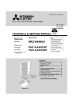
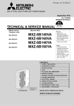
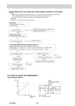
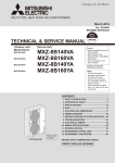
`
CITY MULTI Equipment Start Up Process
_______________________________________________________________________
Purpose
The CITY MULTI Equipment Start up Process is a guideline to assist in conducting the CITY
MULTI system start up. If done properly it can be used in combination with the Extended
Warranty Process to gather required information for that procedure. Generally the R2 series will
take more time than the Y series, so schedule time accordingly. A good rule of thumb is to
reserve one day for every 25 indoor units.
CITY MULTI Checklist
The installing contractor is required to complete all sections of CITY MULTI Pre-start up
Checklist prior to system start up.
Ensure the following:
1) Appropriate line voltage to all system components.
2) Control wiring is terminated correctly and proper voltage is present.
3) All components are correctly addressed. Port assignments are necessary for R2 systems.
4) All field installed components in the refrigerant system must be pressure tested and triple
evacuated.
5) All additional charge has been weighed into the system and service valves opened.
6) Line voltage is applied to outdoor units 12~24 hours prior to start up.
7) An “as built” Diamond System Builder (DSB) file depicting correct addresses, port
connections, line lengths and sizes is required prior to the scheduled start up.
8) Where applicable, the unit must be installed above snowline.
Procedure
1) General Inspection
a) Inspect all system components paying close attention to wiring, refrigerant lines
and drains. Be mindful of correct line sizing and condensate lifts.
b) Be aware that R2 units require the correct twinning kits.
c) Know the minimum/maximum distance required for Y series twinning kits to ensure
piping is correct.
d) The only acceptable way for twinning outdoor units are the examples given in the
installation instructions.
2)
Equipment Power
a) If unsure at what point control wiring was connected to the outdoor unit or units, deenergize the outdoor unit or units for at least 10 minutes.
b) Note the outdoor unit or units LED display; not all error codes will display here, but the
ones that do will not allow the unit to operate. These errors will have to be corrected
before starting the system.
c) Be sure line voltage is present for all indoor components.
d) Always have available the correct Outdoor Technical Service Manual for
troubleshooting error codes.
3) Connecting Options for CMS-MNG-E
a) Connect the MN Converter to any communication terminal; TB3 on the outdoor
unit, TB2 on the Branch Controller (BC) or TB5 on the indoor unit.
b) The MN Converter can be connected at the M-Net terminal block (terminals A and B) of
the Central Controller.
Note: The Central Controller can also be accessed at the same time, via a crossover cable,
for Initial Settings, including grouping, date and time and basic information, etc…
4) Starting Maintenance Tool
a) Do not open the Maintenance Tool program prior to connecting (the MN Converter
Interface) to the City Multi system and your computer via the USB connection.
b) Open Maintenance Tool and select units of measurement.
c) Select Monitor Mode MN Converter.
d) Select Local Connection.
e) Select connection port. This will be a drop down box, after drivers are installed; version
5.07 and later will show the com port and CMS-MNG (See Figure 1).
Figure 1
5) Maintenance Tool Search
a) There are two methods for searching. Select Auto for any startup.
Manual can be used when all addresses are known (See Figure 2).
b) All addresses will be shown in the address grid. If addresses are missing locate the
missing addresses and correct. Missing addresses can be caused by duplicate addressing
or communication wire connection problems. If addresses are changed, cycle power to
the outdoor unit/s for 10 minutes.
c) Be mindful of the address range for all components (See Figure 22).
Figure 2
6) Maintenance Tool Connected Information (R2 only)
a) For R2 systems Connected Information is critical for checking correct port assignments
after the system has started and exited Initial Mode.
b) Connected Info can be viewed from the address grid screen. After the search is complete
place the cursor over the OC that you wish to view, the bottom right side of the screen
will display Connected Information. For R2 systems the port assigned (reflects the
position of the rotary switch SW14 on the indoor control board) will also be displayed
(See Figure 3).
c) For R2 systems Port assignments can also be viewed from the Monitor screen in the IC
information area. This is useful when verifying Port assignments (See Figure 13).
Figure 3
7) System Information
a) System Information must be saved and submitted with monitored run time. Be
sure all information is correct. For Y series, once all addresses are correct the
information can be saved by clicking on File at the top right of the address grid screen,
then click, Save System Info (See Figure 4). The information will save and store in
exactly the same manner as run time information and both will be in Offline Analyze.
Offline Analyze will be one of the options when you first open Maintenance Tool on the
Select Monitor Mode screen (See Figure 15).
b) For R2 systems, wait until all port assignments are verified before saving system
information.
Figure 4
8) Starting The CITY MULTI System
a) At this point all addresses should be correct and accounted for. All errors up to this
point should have been corrected.
b) To bring up the Monitor screen from the grid screen click the Monitor tab at the top of
the screen, all other tabs will fade then click the OC you wish to monitor. Up to three
systems can be monitored simultaneously (See Figure 5).
c) Once this is done in the correct order, a Confirm tab will appear at the bottom of the
screen. Click on the tab to move to the Monitor screen (See Figure 5).
d) Note the pressure sensors 63HS and 63LS on the outdoor units, PS1and PS3 in the BC
(R2 only). They should all read the same or very close.
e) To start the system, click the Drive Operation tab. This tab will allow control of either
indoor unit (IC) or the Branch Controller (BC). Choose IC this will bring up the
Operation screen. From here you can give individual commands or batch commands
(See Figure 6).
f) The Operation screen will populate with the lowest addressed IC on the system you are
monitoring. To change addresses simply click Change at the top of the screen and
move to the next address (See Figures 7 & 8).
g) To conduct a batch command select All at the top of the Operation screen. Be mindful if
there are multiple refrigeration circuits (outdoor units) daisy chained at TB7 all the IC’s
seen on the address grid will start (See Figures 9 & 10).
h) Selecting Test Run Heating or Cooling will allow the system to run for two hours in
whatever mode selected. Both set point and return air will be ignored during this period.
i) The outdoor unit or units will start in Initial mode. Wait until Ordinary mode to judge
the system’s performance. Keep in mind the data required the Extended Warranty Report
must reflect all indoors operating in Test Run heat or cool and the outdoor unit or units
in Ordinary mode.
j) For Y and S series only, if the system is judged to be operating correctly, the start up
process is complete. Information on saving and exporting data will be in Section 10.
Figure 5
Figure 6
Figure 7
Figure 8
Figure 9
Figure 10
9) Verifying BC Port Assignments R2 Only
a) Have System Information present for reference while verifying port assignments.
b) Be sure system operation mode is Ordinary, and that all the indoor units are in Test Run.
This allows ports assignments to be verified while not being concerned with indoor and
outdoor units stopping.
c) In cooling all TH2 temperatures should average between 35 ~ 50 degrees.
d) In heating mode all TH3 temperatures should be above 125 degrees.
e) To manually control the BC, click Drive Operations at the top of the Monitor screen
then select BC Operation (See Figure 6).
f) When the BC operation screen populates you will see across the top 1 ~ 9 and A ~ 0,
this represents a 16 port BC. Each port will have A, B, and C solenoids. These are
represented in a vertical row of blocks beneath each port. The blocks will have a 0 (0 =
closed) or 1 (1 = open) in each. Here you can command the solenoids open or closed by
clicking the block. The fourth vertical block allows you to Fix or Cancel the command
by clicking this block. To send the command select Transmission on the center left side
of the screen (See Figures 11 & 12).
g) Close the ports for the indoor address you are checking (A & C for cooling, B for
heating) then close the BC operation screen. Now check for temperature change on the
indoor unit, TH2 if in cooling mode, TH3 if in heating mode (See Figures 12 &13).
h) Be mindful of all indoor units; if the port assignment is incorrect the temperature change
can be seen on another indoor unit. If this occurs, note the indoor unit address and port
assignment and continue verifying ports. All corrections can then be made at the same
time when verification is complete.
i) After all ports have been verified or corrected, system information can be saved for the
Warranty Report.
Figure 11
Figure 12
Figure 13
10) Saving and Exporting Data
a) When viewing the Monitor screen, Maintenance Tool is recording the data at
approximately one minute intervals. When exiting the Monitor screen a Confirm Data
Save box will appear asking if you would like to save the data. Here you can name the
data and write comments (See Figure 14).
b) When submitting data for the Extended Warranty Process ensure all files submitted for a
single system reflect the same name. This will avoid confusion when information is
received from large sites with multiple systems.
c) The data is saved in Offline Analyze. Offline Analyze is selected from the Select
Monitor Mode screen (See Figure 15).
d) Here you may view the saved data simply by highlighting the data and clicking on it.
(See Figure 16).
e) To export, highlight the data then click export. Maintenance Tool will zip the data. The
zipped file must be imported into Maintenance Tool for viewing (See Figure 17).
Figure 14
Figure 15
Figure 16
Figure 17
11) Setting Up System Auto Restart Function
Auto restart is a function of the indoor control board. With the introduction of software 10.02,
indoor unit function settings can be changed. This gives the indoor unit the ability to restart after
power failure no matter how power is reapplied. To accomplish this perform the following steps.
a) From the address grid screen select an indoor unit address then Optional Set (See Figure
18).
b) When the Optional Setting screen populates select IC Function-Item Setting (See
Figure 19).
c) The IC Function-Item Setting Box will populate with the indoor address selected from
the previous screen (See Figure 20).
d) Change the Item No. 68 and the Item Value to 2 and select Set. This will send the new
function to the selected address board.
Figure 18
Figure 19
Figure 20
Figure 21
Figure 22