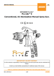
1
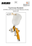
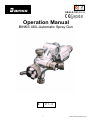
SB-E-2-150 ISS.04
Operation Manual
BINKS 460–Automatic Spray Gun
P1–8
E
1
© 2013 Finishing Brands UK Ltd.
Operation Manual
460 Automatic Spraygun
Important
Read and follow all instructions and Safety Precautions before using this
equipment
Description
A lightweight automatic spray gun for small work suitable for use with most solvent based coating materials.
The design features a single air supply to operate the single acting cylinder and provide the atomizing air. A
remotely positioned two way control valve (supplied by user) triggers the gun. Coating material supply is by a
pressure feed system.
IMPORTANT: These guns are not designed for use with highly corrosive or highly abrasive coating material
and if used with such materials it must be expected that the need for thorough cleaning and/or the necessity
for replacement parts will be increased. If there is any doubt regarding the suitability of a specific material,
advise what material is to be used and/or submit a sample for test.
MODELS
The automatic spray gun type Binks 460 complies with ATEX regulations 94/9/EC, protection level II 2 G X
T6 suitable for use in Zones 1 & 2.
Gun Ref
Tip size
Tip model
Tip reference
Needle Ref
Air Cap model
Air cap ref
103010
0.75 mm
J930SS
200361
180086
J92P
200833
103013
1.0 mm
J940SS
200362
180380
J92R
200834
103019
1.5 mm
K960SS
200363
180087
K92P
200838
103027
1.0 mm
J940SS
200362
180086
J92P
200833
103058
0.75 mm
J930SS
200361
180086
J92R
200834
103062
1.0 mm
J940SS
200362
180086
J92S
200831
103081
0.5 mm
J920SS
200360
180086
J92P
200833
EC Declaration of Conformity
We, Finishing Brands UK Limited, Ringwood Rd, Bournemouth, Dorset, BH11 9LH, UK, as the manufacturer of the
Spray gun model 460, declare, under our sole responsibility that the equipment to which this document relates is in
conformity with the following standards or other normative documents:
BS EN 292-1 PARTS 1 & 2: 1991, BS EN 1953: 1999; and thereby conform to the protection requirements of
Council Directive 98/37/EEC relating to Machinery Safety Directive, and;
EN 13463-1:2001, council Directive 94/9/EC relating to Equipment and Protective Systems intended for use
in Potentially Explosive Atmospheres protection level II 2 G X.
D. Smith, General Manager
30th January 2013
Finishing Brands UK Limited reserves the right to modify equipment specification without prior notice.
2
SAFETY WARNINGS
Fire and explosion
Solvents and coating materials can be highly flammable or combustible when sprayed.
ALWAYS refer to the coating material supplier’s instructions and COSHH sheets
before using this equipment.
Users must comply with all local and national codes of practice and insurance company
requirements governing ventilation, fire precautions, operation and house-keeping of
working areas.
This equipment, as supplied, is NOT suitable for use with Halogenated
Hydrocarbons.
Static electricity can be generated by fluid and/or air passing through hoses, by the
spraying process and by cleaning non- conductive parts with cloths. To prevent ignition
sources from static discharges, earth continuity must be maintained to the spray gun
and other metallic equipment used. It is essential to use conductive air and/or fluid
hoses.
Personal Protective Equipment
Toxic vapours – When sprayed, certain materials may be poisonous, create irritation or
are otherwise harmful to health. Always read all labels, safety data sheets and follow
any recommendations for the material before spraying. If in doubt, contact your
material supplier.
The use of respiratory protective equipment is recommended at all times. The type of
equipment must be compatible with the material being sprayed.
Always wear eye protection when spraying or cleaning the spray gun.
Gloves must be worn when spraying or cleaning the equipment.
Training – Personnel should be given adequate training in the safe use of spraying equipment.
Misuse
Never aim a spray gun at any part of the body.
Never exceed the maximum recommended safe working pressure for the equipment.
The fitting of non-recommended or non-original spares may create hazards.
Before cleaning or maintenance, all pressure must be isolated and relieved from the equipment.
The product should be cleaned using a gun-washing machine. However, this equipment should
not be left inside gun-washing machines for prolonged periods of time.
Noise Levels
The A-weighted sound level of spray guns may exceed 85 dB (A) depending on the setup being used. Details of actual noise levels are available on request. It is
recommended that ear protection is worn at all times when spraying.
Operating
Spray equipment using high pressures may be subject to recoil forces. Under certain
circumstances, such forces could result in repetitive strain injury to the operator.
3
© 2013 Finishing Brands UK Ltd.
SPECIFICATIONS
Maximum WORKING PRESSURE
Air supply P1 :
Material supply P2 :
Min Cylinder Operating pressure :
Maximum service temperature :
7 bar
7 bar
4 bar
40° C
Universal Hose Connection
Atomization air:
1 / 4„‟BSP/NPS
Cylinder air:
1 / 4‟‟BSP/NPS
Material:
1 / 4‟‟BSP/NPS
MATERIAL of construction
Gun body
Tip
Needle
Aluminum
Stainless steel
Stainless steel
INSTALLATION
IMPORTANT: In order to ensure that this equipment reaches you in first class condition, protective coatings,
rust inhibitors, etc., have been used. Flush all equipment through with a suitable solvent before use to remove
these agents from material passages.
Note: A single hose supplies both atomizing and cylinder air. To prevent un-atomized coating material being
expelled from the nozzle at the end of the spray cycle, all air should be exhausted through the gun. It is
recommended that a two way valve should be fitted in the control line. If a three way valve is used, install a
plug in the exhaust port.
Mount gun using the 12.7mm (1/2") rod or stud diameter and secure with screw 164392
HOSING
Use filtered regulated air supply. The minimum air supply pressure required to operate the cylinder is 4.5 bar
(67 ibf/in²) Connect air supply to connector 184574 indicated by markings “AIR” on the gun body. Connect
coating material to the connector184574 on the gun body.
EARTHING the Spray gun must be earthed to dissipate any electrostatic charges which may be created by
fluid or air flows. This can be achieved through the Spray gun mounting, or conductive air/fluid hoses.
Electrical bond from the spray gun to earth should be checked with an ohmmeter. A resistance of less than 106
Ohms is recommended.
WARNING: See instructions under “Replacement of Parts”.
Recommended hose sizes up
To 10m (34ft) long: Air Supply: 8mm (5 /16") bore,
To 5m (17ft) long: Air Supply: 6mm (1 /4") bore,
Material: 8 mm (5 /16 ") bore.
Material: 6 mm (1 /4 ") bore.
4
Order No.
Description
Qty
1
KIT
parts
1
184573
SCREW
1
INNER SPRING
1
1
184574
CONNECTOR
2
161030
O RING
1
1
184576
PISTON
1
20-4146
O RING (ex 161752)
1
1
184577
NEEDLE COLLAR
1
164392
SCREW
1
184578
VALVE STEM
2
166031
CIRCLIPS
2
184579
SLEEVE
2
See CHART
NEEDLE
1
184580
END CAP
1
4900-5-1
BRUSH
1
184581
SCREW
1
180295
PACKING
1
2
184786
HEXAGONAL KEY
1
180296
PACKING NUT
1
1
184788-A
SPANNER
1
184963
FAN/ATOM CONTROL
2
200069-BINKS
GUN BODY
1
Order No.
Description
Qty
160170
OUTER SPRING
160171
180380
SEAL for TIP
1
2
183981
LOCK NUT
1
See CHART
TIP
1
184533
NUT
2
1
See CHART
AIR CAP
1
Kit Reference 250035: Spares parts kits recommended quantities are based on one year usage for medium
product sprayed.
5
© 2013 Finishing Brands UK Ltd.
E
OPERATION
1.
Mix, prepare and strain the material to be sprayed according to the paint manufacturers
instructions. Use a lint free mesh to strain the material.
2.
Adjust the spray gun controls and atomizing pressure before turning on the air and coating material
supplies.
2.1. Fan pattern valve 184963 at the bottom of gun body (head side). Turn adjusting screw to fully open
position, by turning counter-clockwise.
2.2. Atomizing control valve 184963 at the top of the gun body. Turn adjusting screw to fully open
position, by turning counter-clockwise.
2.3. Needle adjustment. Fully close needle adjusting screw184581, release locknut 183981, turn
clockwise until resistance is felt, then turn to the fully open position by turning counter-clockwise
ten turns and secure with locknut 183981.
3.
Regulate the air supply pressure to 4,5 bar (67 lbf/in²) and coating material pressure to 1 bar (15
lbf/in2)
4.
Turn on air and coating material supplies and test spray by operating control valve. The
recommended spray distance is 150 mm (6"). If the finish is too wet, reduce the coating material
supply pressure, or turn the needle adjusting screw 184581 fully clockwise then gradually open
until the desired pattern is achieved. If the atomization is too coarse increase the air pressure. The
spray width can be reduced from fan to round by turning fan adjusting valve 184963 at the bottom
clockwise.
NOTE: If both „FAN‟ and „ATOM‟ valves 184963 are closed the air supply operates the cylinder
only and will allow coating material to be jetted from the nozzle.
5.
To prevent accidental discharge of coating material, always turn off and release pressure when the
gun is not in use.
PREVENTIVE MAINTENANCE
FLUSHING THE SYSTEM.
1.
2.
3.
4.
Turn off coating material supply and relieve pressure.
Close both air valves 184963 „FAN‟ and „ATOM‟.
Replace coating material with a suitable solvent, reduce pressure and turn on supply.
Turn Remove air cap, trigger the gun by operating the control valve. Flush system until clean.
Clean air cap by immersing in solvent, brush or wipe clean. If any holes in the air cap are blocked use a
toothpick or broom straw to remove the obstruction. Never use a steel wire or hard implement which
will damage the air cap and result in a distorted pattern.
Lubrication: Daily lubricate with light mineral oil the valve stems 184578 and needle seal 180295
through holes in seal retainer 180296.
Occasionally coat the gun body cylinder section and springs (160170 & 160171) with mineral based
grease.
6
© 2013 Finishing Brands UK Ltd.
E
REPLACEMENT OF PARTS
Tip 2003**:
Remove parts 184580 end cap with needle adjusting screw and its lock nut, 160171 inner spring and
160170 outer spring and unscrew tip 2003** from body.
Caution: Replace any worn or damaged parts. Replace tip 2003** and tighten.
Recommended torque 13-14 Nm (115-125 lbf in²).
Fit parts 184580 end cap, 160171 inner spring and 160170 outer spring.
Valve assy 184963 :
Caution: Always turn stem valve 184578 fully counter-clockwise before fitting or removing valve
assembly 184963 from gun body.
Remove valve assembly 184963 from gun body by removing parts 184579 valve body. It‟s
recommended to replace the complete air valve if damaged.
Packing 18295:
Remove parts 184580 cap with needle adjusting screw and its lock nut, 160171 inner spring and
160170 outer spring and withdraw needle 1800** and piston 184576, unscrew the seal retainer 180296
and remove the packing 180295. Lubricate new packing with mineral oil, place the packing in front of
the retainer and screw it into gun body. Tighten retainer sufficiently to seal but not to impede free
needle movement. Lightly coat „0‟ rings 20-4146 & 161030 with mineral based grease.
Fit needle and piston assembly into gun body.
Reassemble parts; 160171 inner spring and 160170 outer spring & 184580 end cap.
Needle 1800**:
Remove parts 184580 cap with needle adjusting screw and its lock nut, 160171 inner spring and
160170 outer spring and withdraw needle 1800** and piston 184576.
Unscrew the locking screw 184573 at the back of the needle collar 184577, unscrew the needle
1800**. Replace the needle if damaged, screw the new needle into the collar until you will leave 1,2
mm free movement to the piston before to operate on the needle collar, this gap can be measured by
maintaining the needle in position shut and measuring the piston movement sliding on it. Tight the
locking screw 184573. Tighten retainer sufficiently to seal but not to impede free needle movement.
Lightly coat „0‟ ring 20-4146 & 161030 with mineral based grease. Fit needle and piston assembly into
gun body.
Reassemble parts; 160171 inner spring and 160170 outer spring & 184580 end cap.
Piston ‘0’ ring 20-4146 & 161030:
Remove parts 184580 cap with needle adjusting screw and its lock nut, 160171 inner spring and
160170 outer spring and withdraw needle 1800** and piston 184576.
Replace „0‟ ring 20-4146 & 161030, lightly coat „0‟ ring with mineral based grease.
Fit needle and piston into gun body. Reassemble parts.
Connectors 184574:
Remove connector 184574 and clean threads in gun body.
Apply a medium strength thread locking/sealing compound to the external threads of the new
connector.
Screw into gun body and tighten. Recommended torque: 14 Nm (125 lbf in).
© 2013 Finishing Brands UK Ltd.
7
E
SERVICE CHECKS
CAUSE
A
B-C
1) No pressure at the gun
2) Piston stops moving
3) Screw 184581 not properly adjusted
CORRECTION
A
1) Material build-up on air cap/fluid tip
B-C
1)
2)
3)
Check air/material lines
Clean
Adjust
1)
Clean air cap/fluid tip
1)
Thin or reduce material flow
D
1) Material too thick or too much
D
E
1) Not enough material
E
1)
F
1) Insufficient material in tank or an obstruction in
the hose.
2) Loose or damaged fluid tip
F
1)
2)
Fill tank or clear obstruction
Tighten or replace.
G
1) seal worn 180295
2) Seal retainer 180296 loose
G
1)
2)
Replace seal
Adjust
H
1) Dry packing 180295
2) Worn or damaged fluid tip 2003** or needle
1800**
3) Seal retainer 180296 tight
H
1)
2)
3)
Replace
Replace
Adjust
Reduce air pressure or increase material flow
Finishing Brands UK Limited,
Ringwood Road,
Bournemouth,
BH11 9LH,
UK.
Tel.No. +44(0)1202 571111
Fax No. +44(0)1202 581940
Website address http:// www.finishingbrands.eu
Registered office:
Finishing Brands UK Limited,
400, Capability Green,
Luton,
Bedfordshire,
LU1 3AE,
UK.
Registered in England: No. 07656273
Vat No. GB 113 5531 50
8
© 2013 Finishing Brands UK Ltd.