1
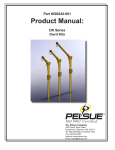
Air Balancers- Advanced Learning Objectives At the conclusion of this module, you will understand IR Zimmerman Air Balancer: • Capabilities • Balancer Operation • Controls Operation and Adjustment Audience Ingersoll-Rand sales, distributors, customer service, engineering and service personnel Executive Summary The Balancer has smooth operation, variable capacity, multiple control choices, multiple mounting options and minimal air consumption. The Balancer replaces hoist applications or as part of a complete lifting system to improve ergonomics and increase production. Understanding the operation and function of the balancer and various controls is an important factor in the proper use of the balancer system. We will discuss the adjustment, inspection and operation of the balancer and controls. Module Preview 1. If a balancer with ZA controls allows a load to drift to the floor in less than a minute what is the problem? ___ Leak to atmosphere ___ Hook balance incorrectly set ___ Low air supply pressure 2. When facing the end cover which direction does the reel rotate? ___ Counterclockwise ___ Clockwise 3. If air pressure is released from the piston chamber, the load will ______. ___ Raise ___ Lower ___ Stay in place 4. Which control is best suited for a lifting or hoisting application? ___ ZA ___ BA ___ EA Page 1 of 21 Configuration The Balancer is a configured product. The sequence of letters and numbers represent the balancers controls, rated capacities, travel and options. The graphic below depicts a configured balancer model number. Controls ZA Capacity W Wire Rope Suspension Z-Stop 032 080 Travel S A2 Options Capacity Zimmerman has 5 basic models of Balancers, with rated capacities of 50, 150, 200, 350, and 500-lb. The rated capacity is based on a supply pressure of 100-psi at the balancer. The capacity of the Balancer decreases as the air pressure decreases. The Balancers can be configured to handle up to 2000-lbs. by adding reeve blocks or operating units in tandem. ¾ Operating Capacity of a balancer is determined by actual (plant) operating air pressure. “Plant operating” pressure is the pressure that is available during normal operations. Each pound of pressure below 100-psi is a 1% decrease in Balancer capacity. To determine the operating capacity of a Balancer at any air pressure, convert the air pressure into a decimal. Air Pressure ÷ 100 = Capacity Factor (50 psi pressure÷ ÷ 100 = .50 Factor) Multiply the capacity factor by the rated capacity of the Balancer to determine the operating capacity. Capacity Factor x Rated Capacity = Operating Capacity (.50 Factor x 350-lb Rated Capacity = 175-lb. Operating Capacity) Page 2 of 21 Plant operating air pressure (PSI) 100 90 80 70 60 ¾ 50 lb. Balancer operating capacity 150 lb. Balancer operating capacity 200 lb. Balancer operating capacity 350 lb. Balancer operating capacity 500 lb. Balancer operating capacity 50 45 40 35 30 150 135 120 105 90 200 180 160 140 120 350 315 280 245 210 500 450 400 350 300 Balancing or Lifting The Balancer stalls when the total load is equal to its operating capacity, as the load increases; maximum speed decreases. For balancing applications, the total load on the balancer should not be greater than 60% of its operating capacity for optimum performance. For lifting applications, the total load on the balancer should not be greater than 80% of its operating capacity for maximum performance. ¾ Reeve or Tandem Option To increase the operating capacity of the balancer a reeve block can be used, pass the wire rope through the pulley and tie the dead end of the rope to the padeye at the bottom of the Balancer housing, this action doubles the capacity of the Balancer. A 500-lb. Balancer becomes a 1,000-lb. Balancer. The disadvantage of this action is that it cuts maximum travel in half. A Balancer with 80-in. of travel is cut to a maximum of 40-in. Reeve blocks are not available for the 50 and 150-lb. balancers. The second option is to use Balancers in tandem. Two balancers are tied to a common control system and a single hook. Two 500-lb. Balancers become a 1000-lb system. The advantage is that there is no reduction in travel. The disadvantage of this method is the expense of two balancers. Travel Each Balancer is supplied with a predetermined amount of wire rope. The total length of rope is greater than the capacity of the reel. Not all of the supplied rope will wind onto the reel. The purpose of the excess rope is to accommodate various installation heights. Remove excess wire rope at the completion of installation. Each balancer is also supplied with a maximum amount of straight travel, which is more than an operator’s reasonable and comfortable, ergonomically sound, reach. Page 3 of 21 The 150, 350 and 500lb. Balancers have 80 inches of travel. The 200 lb. Balancer has 120 inches of travel. The 50 lb. Balancer has 60 inches of travel. Remember that installing a reeve block will reduce the travel by half. Note: 50 & 150 lb. units reeve block is unavailable. Balancer Length of Rope Straight Travel Reeved Travel Capacity (Feet) (Inches) (Inches) 50 lb. 12 60 N/A 150 lb. 200 lb. 350 lb. 500 lb. 20 30 30 30 80 120 80 80 N/A 60 40 40 Exercise 1 1. How many models of balancers does IR provide? ___One ___Three ___Five 2. What is the operating capacity of: 350-lb. Balancer at 55 psi = _____ 200-lb. Balancer at 95 psi = _____ 3. What does the "S" represent in the balancer model number? ___Stand Alone ___Secondary ___Z-Stop 4. If a 200lb balancer is reeved how many inches of travel, will it have? ___120 ___60 ___40 ___80 5. How many inches of travel do 500lb. Balancers have? ___60 ___120 Balancer Function The Balancer uses the same principle as a single acting air cylinder. Air pressure passes into the piston chamber to raise the load, while gravity and the release of pressure allow the load to lower. This design requires minimum air consumption. The balancer consumes approximately 1/8 of a cubic foot of air per complete cycle. An average hoist will consume up to 4 cubic feet of air per cycle. Z-Brake Z-Brake Reel Reel Thrust Bearing Thrust Bearing Piston Piston End Cover End Cover A fixed Ball Screw runs through the Page 4 of 21 Ball Screw and Nut Ball Screw and Nut End Cap End Cap Housing Housing center of the Balancer. A Valox Reel, with a Ball Nut pressed into one end and a Thrust Bearing pressed into the other, rides on the Ball Screw. A Piston pushes against the Thrust Bearing. The Reel rotates counterclockwise (facing the end cover) along the length of the Ball Screw, lifting the load. When pressure in the piston chamber releases, the load counter-rotates the Reel and lowers. When the load is stopped the air trapped in the piston chamber, acts as a cushion balancing the load until the load is moved or the controls are manipulated. Balancer Inspections The balancer should be inspected annually for condition of the internal components and lubrication. The balancer may be serviced while installed on the overhead rail. Refer to the Balancer Service Manual, form MHD56151 for Preventive Maintenance instructions. Z-Brake Z-Brake is the name of our patented Safety Retraction System. The Z-Brake will prevent uncontrolled upward travel of the wire rope if the load is lost or the wire rope breaks. It is installed in the End Cover as a standard part of the balancer (except in the 50 lb. Balancer). The Z-Brake activates by centrifugal force through Brake Rods that engage the Reel. When the speed of the Reel overcomes the Brake Spring tension, the Z-Brake will engage. The Z-Brake should be checked during installation for proper operation of the brake in the work area. The Z-Brake sensitivity can be adjusted. Moving the spring inward, will cause the brake to engage more quickly, the lifting speed will be slower. Sensitivity is decreased by moving the spring outward, which causes the brake to engage more slowly and allows faster lifting speeds. Operate the balancer very slowly in the up direction until a load is attached to avoid accidental engagement of the Z-Brake Train operators to release the up lever if the load stops suddenly or begins to jerk. Then depress the down lever to reset the Z-Brake. Page 5 of 21 Maintenance personnel should be notified to adjust the Z-Brake or slow the lifting speed. The Z-Brake should never be used to limit travel as this will cause increased wear and reduce the life of the balancer. If the Z-Brake engages repeatedly during normal operation, it will damage the wire rope, end cover, reel and brake rods. The force generated by the piston when the Z-Brake engages can be sufficient to bend the brake rods, crack the reel or cause core pops in the wire rope. Z-Brake Inspection The Z-Brake should be inspected annually during the normal balancer service. Remove balancer from service. Remove the end cover of the balancer. Brake Rods- Check for security Bent or deformed BearingCheck for smooth rotation Brake ring- Check for excessive gouging and wear Brake arm/padCheck spring holes for excessive wear Check pad area for excessive wear Brake SpringCheck for deformation and over center wrap for attachment Check engagement: Grasp the brake rods and rotate them clockwise with a rapid motion. The brake shoe should engage the end cover and stop rotation. Wire Rope Zimmerman Air Balancers incorporate wire rope because it is an inexpensive means to support a load and has excellent wear characteristics. It should provide approximately 250,000 cycles. We use 7 X 19, galvanized, 3/16” wire rope with a working capacity of 1,400-lbs. A fitting is swaged onto the end of the rope that installs into the reel. Page 6 of 21 Wire Rope Inspection The wire rope should be inspected daily. Replace wire rope with any bulges, more than one wire frayed, kinks or abnormal bends. A damaged wire rope will have one or more of these faults. Depress the down lever or lower the handling device to the bottom of balancer travel. Use a gloved hand to carefully slide up the rope, if the glove snags on the wire rope inspect for frays and core pops in this area. Check the entire length of rope up to the wire rope guide. Replace any wire rope found faulty. Repeated loading and unloading of the wire rope causes core pop. The core strand of the rope stretches beyond its limits then the load releases rapidly. The core strand of rope will break and fray or curl into a knot causing a bulge or bend in the wire rope. To prevent core pop the wire rope should always have tension on it or do not allow the wire rope to go slack. Frays occur as part of normal wear. Replace a wire rope at the first sign of fraying. Load Hook The load hook is a Crosby/ Bullard Golden Gate, Lif-Lok self-closing swivel bail load hook. The hook has a working limit of one half ton and an ultimate load of four times the working limit. Load Hook Inspection The load hook should be inspected daily as part of the wire rope inspection. Check the following: Top bail of hook should swivel freely. Tip of hook should align with the self-closing gate. No more than 10% wear is allowed at the base of the hook. No more than 5% wear in all other areas. Quic-Check marks must align with an inch or half inch increment. Page 7 of 21 Z-Stop- Option The Z-Stop is a patented mechanism that will disable the operation of the Balancer if the main air supply is disabled. It consists of an Engagement Plate and a Double Acting Air Cylinder with engagement pin. The Engagement Plate is installed on the Z-Brake rods and rotates with the Reel. It contains slots for the Engagement Pin. Both ends of the Double Acting Cylinder are pressurized. Air pressure from the Piston Chamber attempts to extend the engagement pin through the red 5/32-inch tube. Supply air pressure routes to the front of the Cylinder through the yellow 5/32-inch tube and acts to hold the Engagement Pin back. If the main air supply is disabled or supply pressure drops below the balancer pressure, the Engagement Pin will extend and engage one of the slots in the plate. The Z-Stop will engage before the load lowers 6 inches. When supply air pressure is re-enabled and exceeds the balancer pressure, the air cylinder will begin to retract. However, because of a notch in the end of the Engagement Pin, the load must be raised slightly before the Pin will disengage from the slot in the Engagement Plate. The Z-Stop is not available on the 50 or 150-lb. balancers. All required fittings and tubing are supplied. The Z-Stop can be added to balancers with the Z-Brake installed using the appropriate retrofit kit. Z-Stop Inspection The Z-Stop should be inspected annually as part of the balancer service. Connect an airline to the Z-Stop housing and apply air pressure to extend the Zstop pin. Engagement Pin- Check pin engages fully through plate Bent or deformed Plate- Security to brake rods Warped or bent End Cover- Leakage at pin (inside) Leakage at Z-Stop housing Security and leakage at fitting HousingSecurity of screws Security and leakage at fitting Cracks Page 8 of 21 Exercise 2 1. How often should the balancer be inspected and lubricated? ___ Annually ___ Weekly ___Monthly 2. How often should the wire rope be inspected? ___Monthly ___Annually ___Daily 3. What is the purpose of a Z-Stop? ___Disable the balancer if air supply is lost ___Stop an uncontrolled load ___To limit travel 4. When should the Z-Brake engage? ___Every Cycle ___Rope fails or load is lost ___When supply pressure is lost 5. When should the wire rope be replaced? ___ Annually ___ Weekly ___First signs of fraying Controls Function IR Zimmerman Balancers provide superior load control for precision placement of parts. When properly applied, a balancer can increase production and reduce employee injuries and fatigue. The following table identifies the control options available and their proper application. CONTROL DESCRIPTION APPLICATION LIMITATIONS BA Basic Pressure regulator control Balancing a single loadWeld Gun Multi-spindle Nut Runner Checking Fixture Supplied only on the 50 and 150lb. capacity Balancers BA Z-Servo Pressure regulator control with input amplifying servo Balancing a single load Weld Gun Multi-spindle Nut Runner Checking Fixture Supplied with 200500lb. balancers Above 600lbs. total load the control will lose the ergonomic effect EA Basic Pressure regulator control with adjustment for multiple loads Pendent actuated The variation between UN-LOAD and HILOAD can be a maximum of 40 lbs. EA 2PS Pressure regulator control with adjustment for empty device and loaded device Integrated to device or manually actuated Manifold control with speed adjustments; capable of lifting up to operating capacity of balancer Pendent actuated Balancing of three loads Three mode pendent: HI-LOAD LO-LOAD UN-LOAD Balancing control integrated into a handling device that will pick up only one size or weight part All lifting applications ZA Basic Page 9 of 21 If the total load is above 200lbs. the control will lose the ergonomic effect 80% of operating capacity overall speed will begin to decrease ZA (Zim-Air) Control The ZA is best suited for applications where it would be uncomfortable for an operator to reach for the load. The requirements for operators to bend or reach for a load are reduced through use of the pendent. The ZA control operates similar to a hoist control. When the levers on the pendent are depressed, the Balancer will raise or lower the load. The valves in the pendent operate like an accelerator in a car. The harder you press, the faster the load will move. The levers can be "feathered" to make the load move at a comfortable rate for different operators and loads. There are three adjustments on the ZA manifold. Flow controls on either end of the manifold control the UP and DOWN speed. The center adjustment is a non-relieving regulator that adjusts pressure to the Balancer to prevent the load from drifting down. The air flows across the UP speed control valve on the right side of the manifold, down the black hose to the UP lever. When the lever is depressed the air will flow past the Down (DN) lever valve, up the hose to the Balancer raising the load. When the controls are inactive, the load is in balance and pressure traps in the Balancer. To lower the load, depress the Down lever allowing pressure to escape through the pendent to atmosphere. The top center of the manifold is the Hook Balance Adjust, in the event of a leak; pressure is supplied to the piston chamber to prevent a load from drifting down. The normal setting for this valve is flush with the top of the manifold block, which turns the regulator off. ZA Adjustments 1. Install the manifold to the end cap. 2. Connect the black UP hose to the UP port on the manifold. 3. Connect the gray/ yellow hose (handling device applications) to the DN port on the manifold. 4. Connect main air supply to the right side port of the manifold. 5. Turn on main air supply. Adjust regulator to required air pressure. 6. Rotate hook balance screw clockwise slowly until the wire rope begins to raise, move to the full up position ensure the Z-brake does not engage. Page 10 of 21 7. Install the load hook and handling device to the wire rope in the required position. Refer to "Lash up" instructions in the Balancer Service Manual form MHD56151. 8. Rotate the UP flow control clockwise until snug. 9. If the wire rope is slack- ensure the Z-brake does not engage. 10. Feather the UP lever until tension is applied to the wire rope, then fully depress the UP lever until the load is in the full up position. 11. Depress the DN lever and check speed. 12. Adjust the DN flow control on the manifold counterclockwise to increase speed, clockwise to decrease speed, until the desired speed is achieved. 13. Lower to the bottom of normal travel with tension on the wire rope. 14. Adjust the UP flow control on the manifold counterclockwise to increase speed, clockwise to decrease speed, until the desired speed is achieved. BA (Balance Air) Control The BA control installs on the 50-lb. and 150-lb. capacity Balancers for suspending, balancing and/or manipulating a load. The BA control is for single weight loads only. The BA control is a regulator that mounts to the Balancer (manifold- 150 lb. Units). It is manually adjusted to balance a load at a desired height, but can also be set to slowly raise a load up and out of the operator’s way. The BA control is easy to install and adjust. There is an acorn nut at the base of the regulator to make adjustments. The regulator will supply or exhaust air as the operator moves the load. There is a check valve supplied with the control to be installed in the inlet of the regulator. If air supply is lost the check valve will prevent the air in the balancer from escaping allowing the load to lower. BA Adjustments 1. 2. 3. 4. Connect regulator to balancer. Rotate regulator adjustment knob counterclockwise until it stops. Turn on main air supply. Adjust regulator to required air pressure. Rotate the adjustment knob clockwise slowly until the wire rope begins to raise, move to the full up position. (Ensure the Z-brake does not engage150lb. units only). Page 11 of 21 5. Install the load hook and tooling or fixture to the wire rope in the required position. Refer to "Lash up" instructions in the Balancer Service Manual form MHD56151. 6. Rotate the adjustment knob clockwise until the load is suspended. 7. The correct setting will require equal effort to lift and lower the load. 8. If they require the unit to raise the load out of the way, turn the adjustment knob clockwise until the desired speed is achieved. 9. Tighten the jam nut just above the adjustment knob to maintain the proper setting. EA (Equalize Air) Regulator All applications balancing one or more loads with the 200- 500lb capacity balancers use the EA regulator. The EA regulator is a versatile regulator specially designed for operation with the balancer. The EA regulator has an inlet port with a bronze filter, on the right side, to remove debris in the air supply. The plugged "B" port can provide a filtered supply of air that powers handling device components. The center section is the control and main regulator. The main regulator is the larger upper portion, to provide adequate airflow to the balancer. The control regulator uses a very small volume of air for faster response to operator inputs. The control regulator adjusts with the brass acorn nut at the base of the EA regulator. The trim valve located on the left side of the regulator body sets the balance pressure of the control regulator. If the trim valve is not set correctly it will make the load difficult to move. The normal setting is two turns from closed. Fine-tuning may be required for some applications. If the trim valve is opened too far the load will be difficult to push down. If not opened far enough the regulator will be slow to respond making the load feel heavy. The correct setting will require equal effort to raise and lower the load. To the left of the trim valve is the auxiliary flow valve, which controls the amount of air delivered to the "A" port where the control valve connects. The normal setting for the auxiliary flow has 1/8th inch of the screw head protruding from the regulator body. If the valve is not set properly the control handle/ valve will not receive sufficient air pressure causing erratic operation. The "A" port connects to the control valve. The type of valve varies with different applications. A check valve in the left side of the EA regulator installs over the port to the balancer to trap air in the piston chamber and may prevent a load from drifting Page 12 of 21 down if the air supply is disabled. The spring behind the check valve requires 50psi to open. Exercises 3 1. What is the normal setting for the hook balance adjust? ___Two turns clockwise ___Flush with manifold top ___Screw removed 2. Turning the Up speed control on the ZA manifold clockwise will? ___Increase speed ___ Decrease speed ___No effect 3. What would be the best control for balancing a 25lb. air tool? ___ BA ___ZA ___ EA-2PS 4. What is the purpose of the "B" port on the EA regulator? ___Connect control ___No purpose ___filtered air 5. If the load is hard to push down what EA regulator setting may need adjustment? ___Auxiliary Flow ___Trim ___Hook Balance BA (Balance Air) Z-Servo Control Inherent friction within the Balancer is 10% of a load, so manipulating loads over 100-lbs. can be fatiguing over time. The BA Z-Servo addresses this issue. The BA Z-Servo uses a spring actuating valve to amplify inputs from the operator to reduce the required effort to move a load to 3-5 % of the load. This allows the operator to use less effort to move or manipulate a very heavy load. Air flows from the "A" port of the EA regulator through the control tube to the Z-Servo valve. The Z-Servo vents pressure to atmosphere continuously to keep the load in balance. A die spring placed on the bolt mounted in the base of the ZServo compresses the servo valve against the knurled nut. At all times air can be heard or felt venting at the Z-Servo this keeps the load in balance when not being manipulated. When the load lowers the spring pushes against the Z-Servo valve, venting air to atmosphere until the EA regulator begins to exhaust air to lower the load. When the load moves up the spring relaxes and the amount of air vented at the Z-Servo valve reduces, sending a signal back Page 13 of 21 to the EA regulator to increase pressure to the balancer to lift. The knurl nut at the top of the servo provides fine tuning adjustment of the control. The BA Z-Servo control is supplied on all 200- 500lb. Balancers for balancing applications. BA Z-Servo Adjustments 1. Install the regulator to the balancer. 2. Install the Z-Servo as close to but below the ball stop. Refer to the Balancer Service Manual, "Z-Servo Installation" instructions. 3. Rotate the regulator adjustment knob counterclockwise until 1/2 inch of thread is visible. 4. Rotate the trim valve clockwise until snug, then counterclockwise 2 full turns. 5. Rotate the auxiliary flow valve clockwise until snug. 6. Turn on main air supply. Adjust regulator to required air pressure. 7. Rotate the adjustment knob clockwise slowly until the wire rope begins to raise, move to the full up position ensure the Z-brake does not engage. 8. Install the load hook and tooling or fixture to the wire rope in the required position. Refer to "Lash up" instructions in the Balancer Service Manual form MHD56151. 9. Rotate the regular adjustment knob clockwise until the load raises to the full up position. The speed should be relatively slow. Pull down and release the load and check the speed. 10. Connect the black tube to the "A" port on the regulator. 11. Rotate the auxiliary flow valve counterclockwise until the lowering speed is the same as the lifting speed. "Pinching" off the black tube will pressurize the regulator to raise the load. 12. Raise and lower the load two or three times to verify the speeds are the same. If the speed in one direction is much faster than the opposite direction the load will be difficult to move and may provide erratic operation. 13. Pinch off the black tube and connect the free end to the Z-Servo fitting. 14. Turn the knurled nut at the top of the servo until the load is balanced. Rotating the nut clockwise will increase the balance setting or raise the load. Counterclockwise rotation of the nut will reduce the balance setting and lower the load. 15. Lift and lower the load several times. Equal effort should be required to raise and lower the load. If the load is hard to pull down turn the trim valve clockwise 1/2 turn and check. If the load is hard to raise turn the trim valve counterclockwise 1/2 and check. Page 14 of 21 EA (Equalized Air) Basic Control The EA basic control balances three loads without the need to readjust the control. The EA control is suited for applications where the various loads are within a 40lb. range. If the load variation is greater than 40-lbs., the lightest load may be difficult to lower or may drift up. The port sizes in the pendent prevent any additional air from being released at the pendent flow controls. Air from the "A" port of the EA Regulator flows through the control hose to the EA Pendent. The EA pendent has a rotary thumb switch with three settings: HI-LOAD- Balances heaviest load LO-LOAD- Air vents at the pendent to balance medium load UN-LOAD- Air vents at the pendent to balance lightest load When the pendent is in the HI-LOAD position, the EA regulator setting balances the heaviest load. When the pendent is in the LO-LOAD or UN-LOAD position, balancer pressure releases to atmosphere at the flow controls in the pendent. Set the pendent to the desired load position and the load can be moved by hand with minimal effort. The flow adjustments on the pendent to compensate for LO-LOAD and UNLOAD are in line with the corresponding position. EA Basic Adjustments 1. 2. 3. 4. 5. 6. 7. 8. Install the regulator to the balancer. Install the EA pendent to the "A" port of the regulator. Rotate the control handle to the HI-LOAD position. Rotate the regulator adjustment knob counterclockwise until 1/2 inch of thread is visible. Rotate the trim valve clockwise until snug, then counterclockwise 2 full turns. Rotate the auxiliary flow valve clockwise until snug. Turn on main air supply. Adjust regulator to required air pressure. Rotate the adjustment knob clockwise slowly until the wire rope begins to raise, move to the full up position ensure the Z-brake does not engage. Page 15 of 21 9. Install the load hook and tooling or handling device to the wire rope in the required position. Refer to "Lash up" instructions in the Balancer Service Manual form MHD56151. 10. Rotate both the LO-LOAD and UN-LOAD flow controls clockwise until snug. 11. Apply the heaviest load to the tooling or handing device. 12. Rotate the auxiliary flow valve clockwise until snug, then counterclockwise until 1/8th inch of the screw head protrudes from the side of the regulator body 13. Rotate the regulator adjustment knob clockwise until the load is balanced. 14. Lift and lower the load several times. Equal effort should be required to raise and lower the load. If the load is hard to pull down turn the trim valve clockwise 1/2 turn and check. If the load is hard to raise turn the trim valve counterclockwise 1/2 turn and check. 15. Rotate the pendent to the LO-LOAD position. 16. Slowly rotate the LO-LOAD flow control counterclockwise until the load drifts to the floor or full down position. The wire rope should go slack. 17. Remove the heaviest load from the tooling or handling device. 18. Apply the medium weight load to the tooling or handling device. 19. Rotate the LO-LOAD flow control clockwise until the load is balanced. 20. Tighten the jam nut to maintain the proper setting. 21. Lift the load to the full up position. 22. Rotate the pendent to the UN-LOAD position. 23. Slowly rotate the UN-LOAD flow control counterclockwise until the load drifts to the floor or full down position. Allow the wire rope to go slack. 24. Remove the medium weight load from the tooling or handling device. 25. Rotate the UN-LOAD flow control clockwise until the load is balanced. 26. Maneuver the tooling or handling device to the heaviest load and engage the load. 27. Rotate the pendent to the HI-LOAD position. 28. The load should be in balance. 29. Set down the heaviest load and rotate the pendent to the UN-LOAD position. 30. Maneuver the tooling or handling device to the medium weight load and engage the load. 31. Rotate the pendent to the LO-LOAD position. 32. The load should be in balance. 33. Set down the medium load and rotate the pendent the UN-LOAD position. EA-2PS (Position Sensor) Control The EA-2PS control integrates with either a clamp or a vacuum- handling device. The best applications for the EA-2PS control are single weight parts that are to be picked up and set down above the knees and below the shoulders. This control is designed to remain in balance with or without a load attached. The operator maneuvers the load by hand providing superior control. Page 16 of 21 The 2PS-valve mounts to the "A" port of the EA regulator. The valve releases balancer pressure through an adjustable flow control to balance the handling device while empty. A limit switch mounted on the handling device actuates the clamp or vacuum circuit and sends a pilot signal to the 2PS-valve. The 2PS-valve shifts to a blocked port, so pressure does not release. The EA regulator is set to balance the handling device with a load attached. Whether the handling device has a part attached or not, it is in a balanced condition, so the operator can maneuver the handling device by hand without having to manipulate any controls. EA2PS Adjustments 1. Install the regulator and 2PS valve to the balancer. 2. Rotate the regulator adjustment knob counterclockwise until 1/2 inch of thread is visible. 3. Rotate the trim valve clockwise until snug, then counterclockwise 2 full turns. 4. Rotate the auxiliary flow valve clockwise until snug, then counterclockwise until 1/8th inch of the screw head protrudes from the side of the regulator body. 5. Rotate the 2PS-flow control clockwise until snug, then counterclockwise 1 turn. 6. Ensure the tube is connected at the 2PS valve and handling device. 7. Turn on main air supply. Adjust regulator to required air pressure. 8. Rotate the adjustment knob clockwise slowly until the wire rope begins to raise, move to the full up position ensure the Z-brake does not engage. 9. Install the load hook and tooling or handling device to the wire rope in the required position. Refer to "Lash up" instructions in the Balancer Service Manual form MHD56151. 10. Engage the load with the tooling or handling device. 11. Rotate the regulator adjustment knob clockwise until the load is balanced. 12. Lift and lower the load several times. Equal effort should be required to raise and lower the load. If the load is hard to pull down turn the trim valve clockwise 1/2 turn and check. If the load is hard to raise turn the trim valve counterclockwise 1/2 turn and check. 13. Set the part down. The handling device may raise or lower unexpectedly when the part is released. Ensure you are clear of the vertical path at all times during adjustments. 14. Rotate the 2PS-flow control counterclockwise if the handling device raises or counterclockwise if it lowers until the handling device is balanced. 15. Lift and lower the load several times. Equal effort should be required to raise and lower the load. If the load is hard to pull down turn the 2PS flow control counterclockwise 1/2 turn and check. If the load is hard to raise turn the trim valve clockwise 1/2 turn and check. Page 17 of 21 16. Engage and disengage the part checking the balance condition of both the loaded and unloaded handling device. Interlock Control The Interlock is a pilot operated; adjustable spring return valve that will prevent the accidental release of the load while suspended. The air supply to the clamp open/ vacuum release button is routed through the Interlock ports. In the normal state the valve will allow air to these buttons for normal operation. When "interlocked" the valve will shift supplying air directly to the clamp cylinder or vacuum generators. The pilot signal is from the piston chamber of the balancer. The spring return is set for the weight of the empty device. When a load is attached to the end effector additional pressure is required to lift the load. The pressure increase will be sufficient to shift the valve to the interlocked condition. The operator will not be able to release the part until the weight of the load is removed from the end effector or the load is set down. The Interlock valve will return to the normal state and allow the part to be released. Interlock Adjustments Perform the Interlock adjustments as the last portion of the installation, after all control adjustments have bee completed. 1. Raise the handling device to a mid travel position, so the balancer is supporting the entire weight. The Interlock screw threads into an aluminum housing that will rotate with the screw. Hold the aluminum housing while turning the screw. 2. Turn the screw counterclockwise until the Interlock light illuminates (green light) or until 1-1/2 inch of thread is visible. 3. Depress and release (repeatedly) the clamp/ vacuum release button while rotating the Interlock screw clockwise until the clamp opens or blow off air is heard at the vacuum cups or the Interlock indicator extinguishes. 4. Raise and lower the device several times. Check for proper operation of the clamp and vacuum controls. 5. Raise the handling device to the full up position. Page 18 of 21 6. Depress and hold the up lever of the ZA control for three seconds. This will simulate an additional load on the balancer. 7. Depress and release the clamp/ vacuum release button. The clamp should remain closed or not blow off air to the vacuum cups. 8. Check that the Interlock indicator has illuminated (green light). 9. Lower the handling device and engage a part with the end effector. 10. Raise the load 1-inch above the pick up point. 11. Depress and release the clamp/ vacuum release button. The part should remain attached to the end effector. 12. Lower the handling device and release the part at the pick up point. 13. Hold the aluminum housing and tighten the jam nut on the Interlock screw to prevent the setting from changing. Exercises 3 1. Turning the Z-Servo nut clockwise will ______? ___ Raise the load ___Lower the load ___No effect 2. Where is the Z-Servo installed? ___Wire rope ___Balancer ___Tool 3. How many loads can be balanced with the EA Basic control? ___ 1 ___10 ___ 3 4. How does the EA control balance lighter loads? ___Magic ___Weights and pulleys ___Bleed air to atmosphere 5. When does the 2PS-flow control release air? ___Shutdown ___Empty device ___Loaded device Suspension Kits IR Zimmerman offers suspension kits that will fit most any rail type, enclosed track or I-beam/ T-rail. The enclosed track suspension kits incorporate a cast aluminum trolley body with Delrin molded wheels and precision life lubricated sealed wheel bearings. The I-beam/ T-rail kits are stamped and machined steel components. The wheel assemblies have a flat flange and slight taper that will allow adaptation to I-beam, T-rail, Patent track styles with running surface flange width adjustable up to 4 inches. Consult the factory for flange widths larger than 4 inches, custom suspension kits can be designed. All suspension kits come complete with all hardware, trolleys and brackets required to mount the balancer and an instruction sheet. If the instruction sheet is not available refer to the Balancer Service Manual for an exploded view of the suspension kits that can be used for assembly reference. Page 19 of 21 All bolted connections have self-locking nuts that should be replaced when removed. Suspension Kit Inspections The suspension kits should be inspected with the balancer annually. Remove the balancer from service. Remove trolley from brackets. Check for evidence of wear or elongation of bolt and hole. Check trolley wheels for cracks, smooth rotation and no flat spots. Check trolley body for evidence of cracks or damage. Remove brackets from balancer. Check brackets for signs of wear and elongation of bushing and bracket holes and bolt. Module Review We have discussed the operation and inspection of the balancer, load hook, suspension kits, wire rope, Z-brake and Z-Stop. You now have the required expertise to inspect and maintain the balancer. We have also reviewed the operation, installation and adjustment of the standard control kits. The adjustment of the controls is a critical element in the proper operation of the balancer system. Module Review 1. What is the maximum recommended load for a ZA controlled Balancer? ___ 50% of operating capacity ___80% of operating capacity ___100% of operating capacity 2. How many inches of travel do tandem 500lb. Balancers have? ___60 ___40 ___80 3. How many loads can be balanced with the EA Basic control? ___1 ___10 ___3 4. What function does the hook balance adjustment perform on the ZA manifold? ___Send pressure to the piston chamber ___Change down speed ___Change up speed 5. What is the function of an Interlock valve? ___Shutdown handling device ___Prevent dropping a load ___Prevent lifting of a load Page 20 of 21 Glossary Balancing application – a single load that is continuously supported Core Pop- occurs in a wire rope when the core strand of the rope breaks or stretches Design standard pressure – the minimum available air pressure Lifting application – the picking and placing of a load that generally requires the operator to reach or bend in order to perform the task Rated capacity – the maximum capacity of the balancer Operating capacity – the balancer capacity at a specific air pressure Operating pressure – the maximum sustainable air pressure during normal plant operation Reeve block – a block or similar device through which a rope is passed; a pulley Mechanism Static Seal – an O-ring or seal that does not move or rotate once installed. Total load – the total amount of weight of everything that is suspended from the balancer Answers Module Preview: 1. Leak to atmosphere Exercises 1: 1. Lift 2. Never 2. Counterclockwise 3. Lower 4. ZA 3. Core pop 4. First signs of fraying Exercises 2: 1. 192.5-lb. 190.0-lb. 2. 500-lb. Exercises 3: 1. BA 2. ZA 3. EA2PS 4. EA2PS Module Review: 1. 80% 2. 80 3. Three 5. Prevent dropping a load 3. 120 4. A 4. Send pressure to piston chamber Submitted by Daniel K. Richards, Field Service Manager, I-R Assembly Solutions Reviewed by: Joe Paulin, Field Service, I-R Assembly Solutions Umesh Cooduvalli, Marketing, I-R Assembly Solutions Page 21 of 21