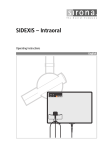
1
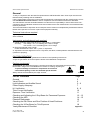
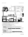
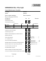
loqelmelp=mäìë=L=mäìë=`ÉéÜ j~áåíÉå~åÅÉ=fåëíêìÅíáçåë Maintenance Instructions Sirona Dental Systems GmbH ATTENTION ! Proper shielding of room and operator position is essential. Since these requirements vary from state to state it is the assembler's/installer's responsibility that all local radiation safety requirements are met. 2 54 72 118 D 3297 D 3297.103.01.03.02 Sirona Dental Systems GmbH Maintenance Instructions General To stay in compliance with the DHHS requirements the ORTHOPHOS® Plus / Plus Ceph must be maintained annually following date of installation. It is the responsibility of the user to insure that the equipment is maintained with the manufacturer's recommended Maintenance Instructions to insure compliance with the Federal Performance Standard. The manufacturer and the assembler/installer are relieved from responsibility in those cases where noncompliance with the standard results from the user's failure to have the manufacturer's recommended maintenance performed. The actual maintenance inspection and consequent service must be accomplished by a trained serviceman. Neither the inspection nor service is part of the equipment warranty. Technical instructions required Operating Instructions Service Manual Instruments and adjustment tools required 1. Digital multimeter Philips PM 2816 rms, Fluke 8000 A, or equivalent. Accuracy: DC voltage ± 0.1 % of reading plus 0.02% of range DC current ± 0.4 % of reading plus 0.1% of range 2. Electromechanical pulse counter, model KESSLER ELLIS KT 203 ±1 pulse, or equivalent. 3. Adjustment set with alignment tool for X-ray beam, test block, needle phantom delivered with the unit (customer's property). CAUTION RADIATION Observe radiation protection guidelines as outlined in the Operating Instructions! X-rays are generated, when the exposure button at the Multitimer is depressed. Caution serviceman! All PC-boards are fitted with electronic components sensitive to electrostatic discharge (ESD). Electrostatic charges are unavoidable due to friction of clothing, carpeting etc. To prevent damage of electronic components do not touch same without putting on the unit mounted special wristlet. Always handle circuit boards by the edge of same. ESD List of Contents General Visual Check Light Indicators and Audible Sound Power Supply Adequacy kV-Verification Tube Current Verification Exposure Time Verification Checking and Adjusting the X-Ray Beam for Panorama Exposure Checking the AES Phantom Radiograph Checking the Ear Olives and Zero Position of Head Positioner Checking the X-Ray Beam for Tele-Exposure Yearly Maintenance Checklist 54 72 118 D 3297 D 3297.103.01.03.02 Page 3 4 5–6 7 8–9 10 11 12 – 13 14 – 15 16 17 18 appendix 3 Maintenance Instructions Sirona Dental Systems GmbH Model-No. SIRONA 59 68 573 D 3200 Serial-No lll 90kV 12mA DC ↓ 2.5 Al / 80 IEC 522 1976 By 257 / 82 Rö - Typ X 1426 X-ray head Röhre / Tube Siemens SR 90 / 15 FN Tube Model-No. 11 17 340 V 1010 Serial-No 0.5 IEC 336 / 82 MADE IN GERMANY ModelNo. SerialNo. ModelNo. SerialNo. SIRONA 15 38 177 D 3200 For identification turn wheel clockwise. Diaphragm 1 5 in. or 6 in. Model-No. Serial-No. 18 88 408 D3200 Diaphragm 2 Model-No. Serial-No. 18 88 382 D3200 Diaphragm 3 10 in. or 8 in. Model-No. Serial-No. 18 88 424 D3200 Diaphragm 4 Model-No. Serial-No. 18 88 366 D3200 Diaphragm 11 Model-No. Serial-No. 51 65 365 D3297 SIRONA 46 80 364 D 3297 X-RAY MADE IN GERMANY Multitimer ModelNo. SerialNo. SIRONA 14 48 450 D 3200 Test block MADE IN GERMANY Test block is part of 'Adjustment Set' SIRONA Unit ModelNo. SerialNo. D 3297 MADE IN GERMANY Visual Check • Look for mechanical damage possibly affecting radiation safety. • Verify that all labels are affixed and legible. Defaced labels must be replaced. Order same from Sirona (address, see rear) in writing stating: Customer Name Customer Address All Model Numbers with Serial Numbers still legible on the unit for identification purposes. For serial numbers see also Installation Report / Warranty Passport. 4 54 72 118 D 3297 D 3297.103.01.03.02 Sirona Dental Systems GmbH Maintenance Instructions 1. C Ceph-mode + – only Unit ON LED V8 - V11 X-RAY A B Ready LED Multitimer Light Indicators and Audible Sound at the Unit. • Unit ON LED: Depress the main switch (1) into the ”I” position. The ”Unit ON LED” in the upper left corner of the Multitimer will then indicate that the unit is ON. The unit adjusts itself automatically, wait about 1 minute. • Digital displays at the Multitimer: The program and exposure parameters employed with the last patient appear. A shows you sequentially the P1 through P16 (P23) panoramic exposure programs and the respective maximum exposure time. Press – + program bottons for correct display check. B gives you the kV/mA matched value pair. The LED over the respective patient symbol must light up. C C lights up, when Ceph–mode is selected. Ready LED over the return button R must blink (When Ready LED blinks, unit is not ready). • Digital displays at the control panel: - The mm value of height adjustment between 000 and 640 from the last patient. - The basic forehead support value of 10.0 mm. - LED indication help messages - Anomaly button LEDs See also Operating Instructions under ”Preparing the Exposure” subchapter ”Switching ON the Unit”. 54 72 118 D 3297 D 3297.103.01.03.02 5 Maintenance Instructions Sirona Dental Systems GmbH Radiation indication X-ray CAUTION RADIATION ! Observe Radiation Protection Guide Lines see Operating Instructions Exposure button X-RAY kV mA Ready LED Return button R Multitimer • Make a panorama exposure: (Ceph–mode not selected) - X-ray head must be in the initial position (Press return button R). - Insert the panorama film cassette into the carriage and swing in the cassette holder. The Ready LED must go out. For more details and possible error messages see Operating Instructions. Set the P1 exposure program using the upper – + buttons. Select 69kV/15mA using the lower – + buttons. CAUTION RADIATION. Depress the exposure button and hold until the exposure terminates automatically The exposure ends when rotation and radiation automatically switch off. The radiation indication X-ray must light up during the exposure period. Simultaneously an audible beep must sound at the unit. • Interrupt an exposure – deadman feature: - Observe a cool-off time of 5 mins. between exposures (automatic exposure blockage). - Setting same as above. Remove and reinsert the film cassette. The Ready LED must go out. - CAUTION RADIATION. Depress the exposure button until X-ray lights up and subsequently release – the exposure must terminate immediately. The Ready LED blinks. • Defective light indicators constitute a safety hazard to the patient as well as to the operator. The user is not permitted to use the unit, until repairs are made ! 6 54 72 118 D 3297 D 3297.103.01.03.02 Sirona Dental Systems GmbH door 1. Maintenance Instructions metal cover ON 2. K1 N N L 300VAC L 3. Terminal strip main cable 4. 5. – 8. see Operating Instructions Power Supply Adequacy • To determine power supply adequacy, the line voltage drop during exposure must be measured. 1. Be sure power cord is not plugged in! Open door and remove metal cover (2 screws). 2. 3. 4. 5. 6. 7. 8. Select 300VAC line voltage range on multimeter. Connect measuring leads to terminal K1, L and N. Plug in power cord and switch unit ON, see Operating Instructions. Press button R at the Multitimer to return X-ray tube head into the initial position. Remove and reinsert the film cassette.The Ready LED at the Multitimer must now go out. Select P1 program and 90kV/12mA at the Multitimer. CAUTION RADIATION! - Depress the exposure button at the Multitimer until meter reading is obtained. Line voltage Max. permissible no load: 187 – 200V line voltage drop: 8V 201 – 220V 9V 221 – 240V 10V 241 – 264V 11V • - - Record reading. Turn unit OFF and remove meter leads. • If the voltage drop is not within the specified range advise the customer, that an adequate power supply must be installed. Refer to Pre-Installation Instructions. Disconnect unit and do not release for use! 54 72 118 D 3297 D 3297.103.01.03.02 7 Maintenance Instructions 3. Sirona Dental Systems GmbH 1. 2. ON 20VDC com. KV– KV+ KV+ KV – DX1 4. – 5. see Operating Instructions kV – Verification, kV–ramp during panoramic exposure • During exposure the kV is encreased in the central region depending on kV/mA selected up to 17%. This increase can be measured in VDC. 1. Remove covers. For details see Service Manual. 2. Connect digital voltmeter to KV+ and KV– and select range 20 VDC. 3. Switch unit ON. The X-ray head must be in the initial position (return button R),temple support fully open. 4. Select P1 program and 73kV/15mA at the Multitimer. Ready LED above button R must be out. 5. CAUTION RADIATION! - Depress the exposure button until the exposure terminates automatically. • The following values must be obtained – see also diagram on next page. up to 5.25 seconds: 7.3 V ±0.4V, from 6.25 to 7.85 s: 8.03 V ±0.1V, after 8.85 seconds: 7.3 V±0.4V. • Turn unit OFF and remove meter leads. • If specified values cannot be obtained, see Service Manual, ”Radiograph Density in Central Region Incorrect” 8 54 72 118 D 3297 D 3297.103.01.03.02 Sirona Dental Systems GmbH Maintenance Instructions VDC ramp 1.6s 9 nominal 7.3V 8 ramp max. 8.1V nominal 8.0V min. 7.9V max. 7.7V min. 6.9V 7 6 5 6.25 5.25s 4 3 7.85 8.85s 7.05s 14.1s complete P1 exposure time 2 1 0 1 2 3 4 5 6 7 8 9 10 11 12 13 14 s exposure time kV – ramp diagram with program P1 and 73kV/15mA set on the Multitimer and temple support fully open. 54 72 118 D 3297 D 3297.103.01.03.02 9 Maintenance Instructions Sirona Dental Systems GmbH 3. ON 20mADC 2. com. 1. jumper MA– MA+ MA+ MA – DX1 4. see Service Manual Tube Current Verification 1. Remove jumper from MA+/MA – test points. 2. Connect digital ammeter to MA+ and MA– and select range 20 mADC. 3. Turn switch ON. Wait for self-adjustment of the unit. 4. Select service routine S.01. • First measurement - Select P1 program and 60kV/9mA at the Multitimer. The Ready LED must be out. - CAUTION RADIATION! Depress the exposure button and hold depressed until meter reading is obtained. The multimeter shall indicate 9mA ±0.5mA. - - Record reading. • Second measurement Select P1 program and 90kV/12mA at the Multitimer. The Ready LED must be out. CAUTION RADIATION! Depress the exposure button and hold depressed until meter reading is obtained. The multimeter shall indicate 12mA ±0.5mA. - - Record reading. • Switch unit OFF. - Remove meter leads and replace jumper! • If specified values cannot be obtained, see Service Manual, ”Checking theTube Current” 10 54 72 118 D 3297 D 3297.103.01.03.02 Sirona Dental Systems GmbH ON Maintenance Instructions 3. Pulse counter com. 2. To N To L of 110VAC/60Hz power receptacle T1 T0 T0 Terminal strip main cable T1 1. DX1 Exposure Time Verification for Panorama and Tele - Exposure 1. CAUTION! Switch the unit OFF. Switch off the AC power at the on-site cabinet. 2. Connect pulse counter according to the connection diagram above. 3. Switch power ON and unit ON. Wait for self-adjustment of the unit. Move the X-ray tube unit to the start position (press the R key). Set diaphragm 1. • VERY IMPORTANT - Open temple support fully, see Operating Instructions. • • At the Multitimer: Select 73kV/15mA with P1 program for Panorama. CAUTION RADIATION !: Press the exposure key until the X-ray display switches off automatically (complete rotation). The exposure time must be 14.1s±0.7s. nominal 14.1 sec.=846 pulses±38 at 60Hz • • • • • For tele-exposure only: Prepare unit for tele-exposure, see Operating Instructions. At the Multitimer: Select 73kV/15mA with P1 program for Tele-Exposure. CAUTION RADIATION !: Press the exposure key until the X-ray display switches off automatically (complete rotation). The exposure time must be 4s±0.2s. nominal 4 sec.= 240 pulses±10 at 60Hz - - Record average pulse count. Switch unit OFF. If specified value cannot be obtained, see Service Manual ”Checking Exposure Times”. 54 72 118 D 3297 D 3297.103.01.03.02 11 Maintenance Instructions Sirona Dental Systems GmbH ON 3. Beam alignment tool 2. 1. X-RAY 4. kV mA Checking and Adjusting the X-Ray Beam 1. Reattach metal front cover (4 screws with fan washers). Reattach rear plastic cover and plastic front cover (engage below, affix with screws on the top and fit cover caps). 2. Place beam alignment tool vertically in the cassette carriage and move behind the slit cover plate. 3. Turn unit ON. 4. Select Service-Routine S.01 (see Service Manuel) and 90kV/12mA at the Multitimer. 12 54 72 118 D 3297 D 3297.103.01.03.02 Sirona Dental Systems GmbH Maintenance Instructions 6” 5” Film height Wheel 2 Status 1 Pan Correct position of X-ray beam X Y Z RADIATION X-RAY C E kV E mA B A 3mm 5. D 6. 5. Set the diaphragm 1 on the wheel into the position shown. To move the wheel, press button D. X-radiation will only be activated when button D is engaged. • Darken the room. • Activate X-radiation to check correct position of X-ray beam. CAUTION RADIATION! If X-ray beam is not in correct position adjust the X-ray beam position to the corresponding mark 1 of the alignment tool. To do this activate X-radiation. CAUTION RADIATION! Activate X-radiation only for as long as you need to recognize the X-ray beam position. X Beam correction 'HIGH – LOW': Loosen 2 screws E by 1 turn. Set beam via Allen screw A. Retighten screws E. Y Beam correction 'VERTICAL': Loosen 2 screws E. Set beam via Allen screws B and C. Retighten screws E. Z Beam correction 'RIGHT – LEFT': Loosen 2 screws E. Set beam via Allen screws B and C. Retighten screws E. 6. Set the diaphragm 2 on the wheel into the lower vertical position. With the same procedure as above adjust the X-ray beam position to the corresponding mark 2 of the alignment tool. • Final check of X-ray beam position under ”Phantom Radiograph”. 54 72 118 D 3297 D 3297.103.01.03.02 13 Maintenance Instructions Sirona Dental Systems GmbH 4. Open fully 3. Remove Test block 1. 2. X-RAY kV mA 5. AES Checking the AES, Automatic Exposure Selection Enshure Fi Fo 20 is selected (see Operating Instruction) 1. Attach special test block delivered as part of this unit (Adjustment set) to bottom of slit cover plate with adhesive tape. Check that it is exactly vertical. 2. Insert a loaded Orthophos film cassette until it locks in place, see Operating Instructions. 3. Remove any bite block from holder. 4. Open temple support fully! Turn knob counterclockwise. 5. On the Multitimer: Select P1 program. Press AES key. Press patient symbol key on the right. 81kV/13mA is displayed. 14 54 72 118 D 3297 D 3297.103.01.03.02 Sirona Dental Systems GmbH 8. Maintenance Instructions Given AES test values 7. RADIATION X-RAY X-RAY Film density kV kV mA 6. mA + – 6. Adjust film density screw on Multitimer to 03, (mA-display) see also Operating Instructions, chapter "Programming" 7. Prepare unit for exposure, see Operating Instructions. • Take a test block exposure. CAUTION RADIATION! Keep exposure button depressed until rotation and radiation automatically switch off. 8. The kV/mA test value for AES given on the test block must appear in the display of the Multitimer. • If given test values does not appear. Carefully adjust the X-ray beam again, see chapter 'Checking and Adjusting the X-Ray Beam'. • Take another test block exposure. • If given AES test values still does not appear, check the AES – see Service Manual, chapter ”Checking the AES”. 54 72 118 D 3297 D 3297.103.01.03.02 15 Maintenance Instructions Sirona Dental Systems GmbH 4. 3. Paper Film Paper 2. 1 1. 7. 6. Process film RADIATION X-RAY kV 5. Unexposed margin mA 8. a1 a2 a1=a2±0.5mm 80mm±1mm Line distance Phantom Radiograph 1. Fit the needle phantom up to stop. 2. Adjust primary diaphragm 1 at the wheel. 3. Cut out two paper strips as large as the film size. Place the film between the paper strips in the dark room – making sure film and paper strips are level with bottom of cassette! (The paper strips are needed to neutralize the intensifying screens). Attach film cassette to the unit's cassette holder (For details see Operating Instructions). 4. Close temple support fully! Turn knob clockwise. 5. Select program P1 and lowest kV at the Multitimer. The X-ray head must be in start position (Return button R)! 6. CAUTION RADIATION! Initiate the exposure for a complete rotating cycle. 7. Process the film. 0 80mm 8. Check the film: Measure the l . . . . . . . lllll . line distances on the film as shown. NOTE: If distance is 88mm, temple support is open. Close temple support and make another exposure. • 16 If the distances exceed the above tolerances, actuators M2/M3 must be adjusted – see Service Manual. 54 72 118 D 3297 D 3297.103.01.03.02 Sirona Dental Systems GmbH Maintenance Instructions 1. B 2. E 3. white cap large ball 4. X-RAY kV RADIATION E black cap small ball 5. mA Checking the Ear Olives • Metal balls in the adjustment caps E show up as dots on an exposed film. Both dots must coincide. 1. Prepare unit for tele-exposure (for details see Operating Instructions, steps 1. – 6.). 2. Pull out cassette holder to full extent and attach an intraoral film with adhesive tape. 3. Turn button B counter clockwise and position ear olives in X-ray path. 4. Pull out ear olive holders to maximum distance and place adjusting caps E on ear olives. 5. Select 62 kV/2.00 s on the Multitimer and release the exposure. RADIATION! • Develop film to evaluate the position of the dots. • If the dots do not coincide see Installation Instructions, chapter 'Checking and Adjusting the Ear Olives' for correction. 54 72 118 D 3297 D 3297.103.01.03.02 17 Maintenance Instructions Sirona Dental Systems GmbH 3. 2. 1. D 1. 120 3 4. 1 correct position of X-ray beam 4 4.1 4.2 A 10x8 S 8x10 4. 2 90kV/4s RADIATION X-RAY 4. kV mA Checking the X-Ray Beam Positon for Tele – Exposure 1. Move the ear olive holder out of the X-ray beam path. The cassette holder for panorama exposure is still out of the X-ray beam path . 2. Adjust cassette holder to full extent. 3. Head positioner must be in horizontal position, not tilt. 4. Two checks must be made: Select 90kV/4.00s at the Multitimer. 4.1 Check A=ASYMMETRICAL with diaphragm 3 Set diaphragm 3 on wheel (press button D and turn wheel). Set soft-tissue filter to position 120. Engage lateral cassette holder at mark A 10x8. (For optional diaphragm 8x10 in. engage at A 8x10). Insert opened cassette horizontally (for optional diaphragm 8x10: vertically) up to the stop.(Secure with adhesive tape). Activate X-RADIATION — only for as long as you need to recognize the beam position. • If the X-ray beam is not in the correct position, see Installation Instructions chapter 'Adjusting the XRay Beam for Tele – Exposure' for correction. 4.2 Check S =SYMMETRICAL with diaphragm 4 Set diaphragm 4 on wheel. Engage lateral cassette holder at mark S 8x10. Insert opened cassette vertically up to the stop. Activate X-RADIATION to recognize the beam position. • 18 If the X-ray beam is not in the correct position, see Installation Instructions chapter 'Adjusting the XRay Beam for Tele – Exposure' for correction. 54 72 118 D 3297 D 3297.103.01.03.02 loqelmelp=mäìë=L=mäìë=`ÉéÜ vÉ~êäó=j~áåíÉå~åÅÉ=`ÜÉÅâäáëí Customer: Address: Dealer: Address: Date of original installation: Date of inspection: Report of Assembly FD 2579 # Yes SCHEDULE Remarks No All manuals are present Test instruments as required Manufacturer Model Accuracy Last calibrated Voltmeter mAmeter Pulse counter Any mechanical damage noticed All labels are present and legible All indicator lights are OK Radiation indicator X-ray lights up, audible buzzer OK Deadman feature OK Power supply adequate Line voltage: . . . . . . . . . .V Voltage drop: . . . . . . . . . V kV – Verification is OK Tube current is within specified limits 1. Measurement: . . . . . . . mA 2. Measurement: . . . . . . . mA Specified exposure time, panoramic (average pulses) OK Average pulse count: . . . . . . Specified exposure times, ceph (average pulses) OK Average pulse count: . . . . . . X-ray beam position, panoramic OK X-ray beam position, ceph OK Phantom radiograph, line distances within tolerance The unit is in compliance with MFG specified tests and safety Technician: D 3297.103.01.03.02 54 72 118 103.01.03 10.2004 Dealer: 54 72 118 D 3297 19 loqelmelp=mäìë=L=mäìë=`ÉéÜ vÉ~êäó=j~áåíÉå~åÅÉ=`ÜÉÅâäáëí Customer: Address: Dealer: Address: Date of original installation: Date of inspection: Report of Assembly FD 2579 # Yes SCHEDULE Remarks No All manuals are present Test instruments as required Manufacturer Model Accuracy Last calibrated Voltmeter mAmeter Pulse counter Any mechanical damage noticed All labels are present and legible All indicator lights are OK Radiation indicator X-ray lights up, audible buzzer OK Deadman feature OK Power supply adequate Line voltage: . . . . . . . . . .V Voltage drop: . . . . . . . . . V kV – Verification is OK Tube current is within specified limits 1. Measurement: . . . . . . . mA 2. Measurement: . . . . . . . mA Specified exposure time, panoramic (average pulses) OK Average pulse count: . . . . . . Specified exposure times, ceph (average pulses) OK Average pulse count: . . . . . . X-ray beam position, panoramic OK X-ray beam position, ceph OK Phantom radiograph, line distances within tolerance The unit is in compliance with MFG specified tests and safety Technician: D 3297.103.01.03.02 54 72 118 103.01.03 10.2004 Dealer: 54 72 118 D 3297 20 loqelmelp=mäìë=L=mäìë=`ÉéÜ vÉ~êäó=j~áåíÉå~åÅÉ=`ÜÉÅâäáëí Customer: Address: Dealer: Address: Date of original installation: Date of inspection: Report of Assembly FD 2579 # Yes SCHEDULE Remarks No All manuals are present Test instruments as required Manufacturer Model Accuracy Last calibrated Voltmeter mAmeter Pulse counter Any mechanical damage noticed All labels are present and legible All indicator lights are OK Radiation indicator X-ray lights up, audible buzzer OK Deadman feature OK Power supply adequate Line voltage: . . . . . . . . . .V Voltage drop: . . . . . . . . . V kV – Verification is OK Tube current is within specified limits 1. Measurement: . . . . . . . mA 2. Measurement: . . . . . . . mA Specified exposure time, panoramic (average pulses) OK Average pulse count: . . . . . . Specified exposure times, ceph (average pulses) OK Average pulse count: . . . . . . X-ray beam position, panoramic OK X-ray beam position, ceph OK Phantom radiograph, line distances within tolerance The unit is in compliance with MFG specified tests and safety Technician: D 3297.103.01.03.02 54 72 118 103.01.03 10.2004 Dealer: 54 72 118 D 3297 21 loqelmelp=mäìë=L=mäìë=`ÉéÜ vÉ~êäó=j~áåíÉå~åÅÉ=`ÜÉÅâäáëí Customer: Address: Dealer: Address: Date of original installation: Date of inspection: Report of Assembly FD 2579 # Yes SCHEDULE Remarks No All manuals are present Test instruments as required Manufacturer Model Accuracy Last calibrated Voltmeter mAmeter Pulse counter Any mechanical damage noticed All labels are present and legible All indicator lights are OK Radiation indicator X-ray lights up, audible buzzer OK Deadman feature OK Power supply adequate Line voltage: . . . . . . . . . .V Voltage drop: . . . . . . . . . V kV – Verification is OK Tube current is within specified limits 1. Measurement: . . . . . . . mA 2. Measurement: . . . . . . . mA Specified exposure time, panoramic (average pulses) OK Average pulse count: . . . . . . Specified exposure times, ceph (average pulses) OK Average pulse count: . . . . . . X-ray beam position, panoramic OK X-ray beam position, ceph OK Phantom radiograph, line distances within tolerance The unit is in compliance with MFG specified tests and safety Technician: D 3297.103.01.03.02 54 72 118 103.01.03 10.2004 Dealer: 54 72 118 D 3297 22 loqelmelp=mäìë=L=mäìë=`ÉéÜ vÉ~êäó=j~áåíÉå~åÅÉ=`ÜÉÅâäáëí Customer: Address: Dealer: Address: Date of original installation: Date of inspection: Report of Assembly FD 2579 # Yes SCHEDULE Remarks No All manuals are present Test instruments as required Manufacturer Model Accuracy Last calibrated Voltmeter mAmeter Pulse counter Any mechanical damage noticed All labels are present and legible All indicator lights are OK Radiation indicator X-ray lights up, audible buzzer OK Deadman feature OK Power supply adequate Line voltage: . . . . . . . . . .V Voltage drop: . . . . . . . . . V kV – Verification is OK Tube current is within specified limits 1. Measurement: . . . . . . . mA 2. Measurement: . . . . . . . mA Specified exposure time, panoramic (average pulses) OK Average pulse count: . . . . . . Specified exposure times, ceph (average pulses) OK Average pulse count: . . . . . . X-ray beam position, panoramic OK X-ray beam position, ceph OK Phantom radiograph, line distances within tolerance The unit is in compliance with MFG specified tests and safety Technician: D 3297.103.01.03.02 54 72 118 103.01.03 10.2004 Dealer: 54 72 118 D 3297 23 loqelmelp=mäìë=L=mäìë=`ÉéÜ vÉ~êäó=j~áåíÉå~åÅÉ=`ÜÉÅâäáëí Customer: Address: Dealer: Address: Date of original installation: Date of inspection: Report of Assembly FD 2579 # Yes SCHEDULE Remarks No All manuals are present Test instruments as required Manufacturer Model Accuracy Last calibrated Voltmeter mAmeter Pulse counter Any mechanical damage noticed All labels are present and legible All indicator lights are OK Radiation indicator X-ray lights up, audible buzzer OK Deadman feature OK Power supply adequate Line voltage: . . . . . . . . . .V Voltage drop: . . . . . . . . . V kV – Verification is OK Tube current is within specified limits 1. Measurement: . . . . . . . mA 2. Measurement: . . . . . . . mA Specified exposure time, panoramic (average pulses) OK Average pulse count: . . . . . . Specified exposure times, ceph (average pulses) OK Average pulse count: . . . . . . X-ray beam position, panoramic OK X-ray beam position, ceph OK Phantom radiograph, line distances within tolerance The unit is in compliance with MFG specified tests and safety Technician: D 3297.103.01.03.02 54 72 118 103.01.03 10.2004 Dealer: 54 72 118 D 3297 24 loqelmelp=mäìë=L=mäìë=`ÉéÜ vÉ~êäó=j~áåíÉå~åÅÉ=`ÜÉÅâäáëí Customer: Address: Dealer: Address: Date of original installation: Date of inspection: Report of Assembly FD 2579 # Yes SCHEDULE Remarks No All manuals are present Test instruments as required Manufacturer Model Accuracy Last calibrated Voltmeter mAmeter Pulse counter Any mechanical damage noticed All labels are present and legible All indicator lights are OK Radiation indicator X-ray lights up, audible buzzer OK Deadman feature OK Power supply adequate Line voltage: . . . . . . . . . .V Voltage drop: . . . . . . . . . V kV – Verification is OK Tube current is within specified limits 1. Measurement: . . . . . . . mA 2. Measurement: . . . . . . . mA Specified exposure time, panoramic (average pulses) OK Average pulse count: . . . . . . Specified exposure times, ceph (average pulses) OK Average pulse count: . . . . . . X-ray beam position, panoramic OK X-ray beam position, ceph OK Phantom radiograph, line distances within tolerance The unit is in compliance with MFG specified tests and safety Technician: D 3297.103.01.03.02 54 72 118 103.01.03 10.2004 Dealer: 54 72 118 D 3297 25 loqelmelp=mäìë=L=mäìë=`ÉéÜ vÉ~êäó=j~áåíÉå~åÅÉ=`ÜÉÅâäáëí Customer: Address: Dealer: Address: Date of original installation: Date of inspection: Report of Assembly FD 2579 # Yes SCHEDULE Remarks No All manuals are present Test instruments as required Manufacturer Model Accuracy Last calibrated Voltmeter mAmeter Pulse counter Any mechanical damage noticed All labels are present and legible All indicator lights are OK Radiation indicator X-ray lights up, audible buzzer OK Deadman feature OK Power supply adequate Line voltage: . . . . . . . . . .V Voltage drop: . . . . . . . . . V kV – Verification is OK Tube current is within specified limits 1. Measurement: . . . . . . . mA 2. Measurement: . . . . . . . mA Specified exposure time, panoramic (average pulses) OK Average pulse count: . . . . . . Specified exposure times, ceph (average pulses) OK Average pulse count: . . . . . . X-ray beam position, panoramic OK X-ray beam position, ceph OK Phantom radiograph, line distances within tolerance The unit is in compliance with MFG specified tests and safety Technician: D 3297.103.01.03.02 54 72 118 103.01.03 10.2004 Dealer: 54 72 118 D 3297 26 loqelmelp=mäìë=L=mäìë=`ÉéÜ vÉ~êäó=j~áåíÉå~åÅÉ=`ÜÉÅâäáëí Customer: Address: Dealer: Address: Date of original installation: Date of inspection: Report of Assembly FD 2579 # Yes SCHEDULE Remarks No All manuals are present Test instruments as required Manufacturer Model Accuracy Last calibrated Voltmeter mAmeter Pulse counter Any mechanical damage noticed All labels are present and legible All indicator lights are OK Radiation indicator X-ray lights up, audible buzzer OK Deadman feature OK Power supply adequate Line voltage: . . . . . . . . . .V Voltage drop: . . . . . . . . . V kV – Verification is OK Tube current is within specified limits 1. Measurement: . . . . . . . mA 2. Measurement: . . . . . . . mA Specified exposure time, panoramic (average pulses) OK Average pulse count: . . . . . . Specified exposure times, ceph (average pulses) OK Average pulse count: . . . . . . X-ray beam position, panoramic OK X-ray beam position, ceph OK Phantom radiograph, line distances within tolerance The unit is in compliance with MFG specified tests and safety Technician: D 3297.103.01.03.02 54 72 118 103.01.03 10.2004 Dealer: 54 72 118 D 3297 27 loqelmelp=mäìë=L=mäìë=`ÉéÜ vÉ~êäó=j~áåíÉå~åÅÉ=`ÜÉÅâäáëí Customer: Address: Dealer: Address: Date of original installation: Date of inspection: Report of Assembly FD 2579 # Yes SCHEDULE Remarks No All manuals are present Test instruments as required Manufacturer Model Accuracy Last calibrated Voltmeter mAmeter Pulse counter Any mechanical damage noticed All labels are present and legible All indicator lights are OK Radiation indicator X-ray lights up, audible buzzer OK Deadman feature OK Power supply adequate Line voltage: . . . . . . . . . .V Voltage drop: . . . . . . . . . V kV – Verification is OK Tube current is within specified limits 1. Measurement: . . . . . . . mA 2. Measurement: . . . . . . . mA Specified exposure time, panoramic (average pulses) OK Average pulse count: . . . . . . Specified exposure times, ceph (average pulses) OK Average pulse count: . . . . . . X-ray beam position, panoramic OK X-ray beam position, ceph OK Phantom radiograph, line distances within tolerance The unit is in compliance with MFG specified tests and safety Technician: D 3297.103.01.03.02 54 72 118 103.01.03 10.2004 Dealer: 54 72 118 D 3297 28 tÉ=êÉëÉêîÉ=íÜÉ=êáÖÜí=íç=ã~âÉ=~åó=~äíÉê~íáçåë=ïÜáÅÜ=ã~ó=ÄÉ=êÉèìáêÉÇ=ÇìÉ=íç=íÉÅÜåáÅ~ä=áãéêçîÉãÉåíëK = a=POVTKNMPKMNKMPKMO===NMKOMMQ péê~ÅÜÉW=ÉåÖäáëÅÜ= ûKJkêKW= NMR=RUQ mêáåíÉÇ=áå=dÉêã~åó fãéêáã¨=Éå=^ääÉã~ÖåÉ páêçå~=aÉåí~ä=póëíÉãë=dãÄe= c~Äêáâëíê~≈É=PN aJSQSOR=_ÉåëÜÉáã dÉêã~åó ïïïKëáêçå~KÇÉ áå=íÜÉ=rp^W áå=`~å~Ç~W páêçå~=aÉåí~ä=póëíÉãë=ii` QUPR=páêçå~=aêáîÉI=pìáíÉ=NMM `Ü~êäçííÉI=k`=OUOTP rp^ páêçå~=`~å~Ç~ PORM=oáÇÖÉï~ó=aêáîÉ=J=råáí=R jáëëáëë~ìÖ~I=låí~êáç=iRi=RvS `~å~Ç~ lêÇÉê=kç RQ=TO=NNU=a=POVT