1
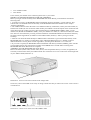
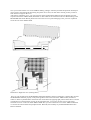
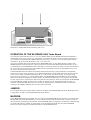
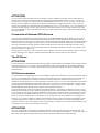
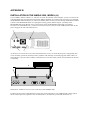
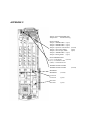
BLIZZARD 2040/2060
T
u
r b
o
Bo
a
r d
U
s
e
r
M
a
n
u
a
l
IMPORTANT ADVICES at the BLIZZARD 2040 SERIES!
Before you begin to read the user manual and to install the board, please consider the following items:
Included in the package is the manual "BLIZZARD 2060 Turbo Board", which is, beside of subtle differences,
suitable for your 2040 . The differences are:
The software installation, as desrcibed in the manual, is complete unnecessary.
Due to that there is no disk included.
In case of an upgrade of your 2040 to a 68060 processor, which we are quite prepared to do for you, you will be
furnished with the then required diskette.
To obtain proper function a "68040.library" must be installed in your "libs:" directory. This library is part of the
operating system and is not available from us. The usage of the latest "Setpatch" version lowers the risc of
incompabilities
PREFACE
Many thanks for choosing our product. With the overwhelming performance of the latest and fastest processor of
the 68k-family, the Motorola 68060, the BLIZZARD 2060 Turbo Board brings along a performance level for the
AMIGA 2000 which was formerly unthinkable in this form and at tis price. With more than 80 MIPS
performance and the high performance of the integrated floating point processor unit (FPU), the AMIGA 2000
becomes a powerful workstation, which is more than suited for today’s most demanding applications such as 3Dcalculations and ray-tracing, image processing, animation or video processing.
Some of the most important features of the BLIZZARD 2060 Turbo Board:
• High-End acceleration board for the AMIGA 2000 with 50 MH-68060 processor with FPU and MMU for
highest and maximum performance
• Four 72-channel standard-SIMM-sockets for the memory expansion up to 128 Mbyte
• main memory (merged assembly is also possible)
• Automatic self-integrating (auto-configurating) memory with optional mirroring of the operating system
(MAPROM-function, deselectable) for additional power increase
• An extremely fast memory layout grants highest data throughput in the fast RAM
• Asynchronous design for full Genlock-compatibility
• Can be reset to 68000-processor through the keyboard for full compatibility with all software (possible with
AMIGA 2000 model „B“ only)
• Integrated Fast SCS-II DMA controller with transmission rates of up to 7 Mbyte/sec. asynchronous and up
to 10 Mbyte/sec. synchronous on the SCSI-bus
• Through DMA - transmission (Direct Memory Access) the processor on the BLIZZARD 2060 Turbo Board
is not charged. Thus, the BLIZZARD 2060 Turbo Board is optimally suited for multimedia-applications
• Solderless and simple assembly in the processor expansion slot of the AMIGA 2000
• High-quality processing in latest SMD-technology
• Build under lisence from phase5 by dce computer service in germany.
Chapter 1
The BLIZZARD 2060 Turbo Board
Scope of delivery
On receipt of the BLIZZARD 2060 Turbo Board please check that the delivery scope is complete. The package
must contain:
• One board (BLIZZARD 2060 Turbo Board)
•
•
Two installation disks
This manual
If one of these parts should not be contained, please refer to your retailer.
IMPORTANT! BEFORE BEGINNING WITH THE ASSEMBLY
Before you begin with the assembly of the BLIZZARD 2060 Turbo Board, you should first consider the
following items.
1. To function correctly, the BLIZZARD 2060 Turbo Board needs special 68060 - specific software. This
software has to be installed before the assembly of the BLIZZARD 2060 Turbo Board. See also chapter
„Software installation“.
2. The AMIGA 2000 has been delivered as two different models by Commodore, namely the older models (A)
and the later models (B). You an find out which model your AMIGA is from the imprint on the left bottom side
of the main board. If you discover here a lable with the imprint „COMMODORE AMIGA 2000“, a serial
number and „MADE IN GERMANY (BSW)“, than your AMIGA is a model (A). With these models, the 68000
CPU has to be removed before you being with the installation of the BLIZZARD 2060 Turbo Board. Please by
all means read the Appendix B „Installation in the AMIGA 2000, model (A)“ before you begin with the
assembly !
3. Find out with which Kickstart-ROM your AMIGA 2000 is furnished. To grant the full functionality of the
BLIZZARD 2060, we urgently recommend the usage of Kickstart-ROM Version 3.1. Should you have a
different Kickstart-version, please read the Appendix A „Working under Kickstart 1.3 or 2.04“ first.
4. If you want to expand your BLIZZARD 2060 Turbo Board with memory modules (SIMMs), please read the
corrresponding chapter first, because the assembly of the SIMMs has to be made before inserting of the
BLIZZARD 2060 Turbo Board into the computer.
ASSEMBLY OF THE BLIZZARD 2060 Turbo Board
Remove all cables (mains cable, monitor cable, mouse, serial and parallel cables), as well as, if applicable, all
externally connected units from your AMIGA 2000. Now loosen the two screws on the lower left and right side
of your AMIGA 2000 (illustration 1).
Illustration 1. Screws on the lower left side of the Amiga 2000
On the rear, remove the middle screw lastly. In doing so make sure that you remove the correct screw as shown
in illustration 2.
Illustration 2. Center screw on the rear of the AMIGA 2000
Now you can take off the cover of the AMIGA 2000 by pulling it cautiously forward and upwards. Should you
notice resistor when taking off the housing lid, please use no force, but look below the lid, possibly a cable or
alike has been caught on the cover.
After having opened the cover, you will recognize on the left beside the 6800 CPU the 86-channel processor
expansion slot of the AMIGA 2000 (illustration 4). The board has to be fitted into this slot. Before fitting in the
BLIZZARD 2060 Turbo Board, please first remove the slot cover plate belonging to the processor expansion
slot at the rear of the AMIGA 2000.
Illustration 3. Cover removal – side view
Illustration 4. Right side view (looking down)
Now you can carefully enter the BLIZZARD 2060 Turbo Board as shown in illustration 5. Please take care that
the BLIZZARD 2060 sits properly in the plastic guidance rail on the front of the AMIGA 2000, and that no
cables or others are jammed below the board. Now fix the board by applying light pressure from above as shown
in illustration 5. If the board sits properly in the appropriate slot, you can now fix the screws of the earlier
loosened slot cover on the rear of the AMIGA 2000. Now you can re-fasten the cover of the AMIGA 2000 and
re-connect all removed cables and peripheral units. Herewith, the assembly of your BLIZZARD 2060 Turbo
Board is finished.
Illustration 5. BLIZZARD 2060 installation (side view)
OPERATION OF THE BLIZZARD 2060 Turbo Board
If you dispose of the Kickstart Version 3.1 in your AMIGA 2000, then the BLIZZARD 2060 Turbo Board is
immediately ready to use, and puts it’s performance at your disposal directly after having been switched on. If
your computer is furnished with a different Kickstart Version (e.g. Version 1.3 or 2.04), then please read the
Appendix A „Working under Kickstart Version 1.3 or 2.04“ first.
If you have installed memory (Fast RAM) on the BLIZZARD 2060, you can define through a jumper if the
MAPROM function which copies the operating system into the faster Fast-RAM shall be activated or not. It is
recommended to let the MAPROM function switched on at all times (always activated ex works), because due to
the 16 bit-wide system architecture of the AMIGA 2000 it expands the operating system ROM-accesses to 32
bit, and so accelerates them considerably.
The BLIZZARD 2060 Turbo Board can be deactivated without having to be de-assembled, if compatibility
problems occur with certain programs. (As in AMIGA 2000 Model „A“ the 68000 CPU has to be removed, the
reset is only working in AMIGA 2000 model „B“!). To de-activate, hold down the key „0“ during booting.
However do not use the key „0“ on the numeral block. The BLIZZARD 2060 Turbo Board is then completely
deactivated, which will readjust the AMIGA 2000 to the standard configuration. however please consider that
not only the processor of the board is deactivated, but also all expansions, which are operated on the BLIZZARD
2060 Turbo Board. So after the deactivation, neither the memory nor the integrated SCSI-II controller are
available. The BLIZZARD 2060 can be re-activated, by keeping the key combination which is required for
resetting (CTR-AMIGA-AMIGA) down for more than 10 seconds.
JUMPER
For a complete description of the jumpers which are available on the BLIZZARD 2060 Turbo Board please turn
to Appendix C „Jumper on the BLIZZARD 2060 Turbo Board“.
MAPROM
On the BLIZZARD 2060 Turbo Board there is a jumper for the MAPROM function. If memory is loaded on the
BLIZZARD 2060 Turbo Board memory, you can load the kickstart into the faster RAM, in order to accelerate
the execution of operating system functions. If the MAPROM jumper is plugged in, the kickstart is automatically
recopied. If the jumper is pulled out, the kickstart is executed from the ROM. The (activated) MAPROM
function occupies 512 Kbyte of the RAM installed on the BLIZZARD 2060 .
MEMORY EXPANSION
Adjustment and recognition of the RAM installed on the BLIZZARD 2060 is completely automatical. For the
memory assembly you need 32-bit-SIMMS, available general under the trade mark PS2-module. The
BLIZZARD 2060 accepts SIMMS or thememory sizes 4MB, 8MB, 16MB, 32MB, and also allows merged
assembly of these SIMS. The organization of the SIMMS may be 32 bit as well as 36 bit. The 36-bit SIMMS are
used in IBM-compatible
PCs, which use the additional 4 bit as parity bit. With the BLIZZARD 2060, these additional bits are ignored.
For the operation in a BLIZZARD 2060 SIMMS with a speed of 70 ns or faster are required.
Please consider that some SIMM-modules of different suppliers are available which do not maintain the
imprinted speed. Especially SIMM-modules which bear e.g. the imprint LaserPrinterMemory (or similar
phantasy labels) are unservicable as memory for computer systems. dce computer service principally
recommends not to use such SIMM-modules.
ASSEMBLY OF SIMM-modules
Put the BLIZZARD 2060 on a plane, hard underground. Be aware that sensitive surfaces could be scratched by
the pins onthe bottom when mounting the memory module, therefore we recommend to use e.g. a magazine as
support. Now align the BLIZZARD 2060 Turbo Board so that the external SCSI-II connector points towards the
right. The memory SIMMS have a recess opening on one side of the contact strip, so that they can not be
mounted upside down. This recess opening must be at the left side when mounting. Insert the Simm at an angle
of aprox 40 flush into the socket, thus the module can be inserted without problems. Then softly press down
both upper corners the SIMM down with your thumbs, until it audibly locks into place. Take care that the metal
hooks left and right besides the fixation holes both lock in over the board of the SIMMS. Take care for all
handling steps, that the SIMs must not be subject to strong mechanical stress.
Note: Generally it does not matter in which sequence resp. in which of the four SIMM-sockets you insert your
SIMM(s).
SOFTWARE INSTALLATION
The included software contains the necessary libraries for the operation of the 68060 CPU, the command
CPU060, an equivalent to the CPU command of the operating system, as well as some tools for the operation of
the 68060 CPU. Through the installation, the 68040.library, if existing, is renamed and the libraries
68040.library and 68060.library are copied into the directory LIBS: furthermore, the CPU060 command is
copied to C: and a drawer with the designation SOFT060 is generated in the system partition which contains the
tools for the operation of the 68060 CPU.
ATTENTION!
The installation of the software must in any case take place before the assembly of the BLIZZARD 2060 Turbo
Board ! Should the operation of a 68000, 68020, 68030 or 68040 Cpu be necessary, then you need make no
modifications of the installed software. The present version of the 68040.library which is delivered together with
the BLIZZARD 2060 automatically recognizes the inserted processor and loads the required library.
The software installation is made through an installation script. Insert the delivered disk and open it through
double mouseclick. Before the final installation, you should doubleclick on the „ReadMe“-file to open it. In this
text, the actual information on the software is contained. The software is then installed through doubleclick on
the INSTALL icon. The program in the SOFT060 directory have their own dcumentation on the disk, the
command CPU060 has, in addition to the arguments of the CPU command, the following arguments:
(NO)SUPERSCALAR (de)activates the superscalar mode of the processor
(NO)BRANCHCACHE (de)activates the branchcache
CHAPTER 2
THE FAST SCSI-II DMA Controller
Connection of already RDB-formatted SCSI-Drives
If you connect a hard disk (or resp. another SCSi-unit) to the BLIZZARD 2060 Turbo Board, which was
formerly operated on a SCSI-controller in the AMIGA and formatted with the RDB (Rigid Disk Block)
according to AMIGA-standard, this unit is immediately ready to use.
After the computer has been started, the partitions existing on this disk must be automatically recognized and,
resp. even booted. If this is not so, contact your retailer in any case, before undertaking further measures.
ATTENTION!
If you want to connect hard disks which you already operate at a different controller, and on which data are
memorized, we urgently recommend to make a safety backup of the hard disk before removal out of the old
system. Each new connection of an already operated hard disk bears the risk – if ever so small – of a data loss
through error at installation or putting into operation. If the backup on floppy disk seems too slow, ask your
retailer if he could take over the backup and re-installation for you (e.g. on a streamer), or if you could borrow a
streamer, possibly against a low fee. We expressively state that we take over no warranty whatsoever for data
losses on hard disks or SCSI-units which have been previously used before being connected to the BLIZZARD
2060 Turbo Board.
Connection of External SCSI-Devices
To the 50-channel HigDensity Fast SCSI-II connector of the BLIZZARD 2060 Turbo Board you can connect
external SCSI-units with a commercial brand SCSI-II cable. Most external SCSI-units are furnished with 50channel Centronics-connections, so that for those a cable with 50-channel SCSI-II-plug on one side and standard
SCSI Centronics 50-pole plug on the other side can be used. Further SCSI-units can then be connected via the
first unit, while between the units generaly cables with 50-channel connection on both sides are used. In any
case, you have to take care of correct bus-termination (see SCSI-bus termination), as otherwise problems with
the data transmission could occur.
During operation, you have to take care that the power supplies of the external units should always be activated
before switching on the computer, and deactivated only after the computer has been switched off.
The SCSI-bus
ATTENTION!
For the connection of external SCSI-units only top-quality screened cables are admitted, which comply with the
valid standards (CE, FCC, or similar). For purchasing such cables, which offer the corresponding attenuation
properties, please turn to your retailer. Please also be aware that external SCSI-units have to fulfill the valid
standard norms!
SCSI-bus termination
To grant a faultless, unimpaired function for the SCSI-bus system, the SCSI-bus has to be terminated electrically
correct. You can think of the SCSI-bus as a ingle cable, which has to have a terminal resistor at each end. The
single units are then directly connected to this cable. It follows that the termination resistors may only be
installed on the first and last unit . In this regard, the controller counts as one unit. (see illustration 6). The SCSImodule on the BLIZZARD 2060 is furnished with an active termination, which automatically switches on and
off, depending on if external SCSI-units are connected or not. (please also see the Appendix C „Jumper on the
BLIZZARD 2060 Turbo Board“ and the chapter „SCSI termination jumper“.)
On the usual SCSI-units such as hard disks, alternation disk drives, or streamers, termination resistors are also
installed. The termination resistors generally are positioned close to the SCSI-plug. If the resistors are socketed,
you can simply remove them if required. Should the resistors not be socketed, (which is sometimes the case for
newer SCSI-units with SMD-soldered resistors or active termination on the unit-side), there generally exists a
jumper or switch on the SCSI-unit, wiht which it can be switched off. For the localization of such jumpers or
switches, or if you have problems to identify the termination resistors, please refer to the documentation of the
corresponding SCSI-unit. With external units (e.g. scanners) or external drives it could be, depending on the
supplier or delivery scope, that instead of resistors installed on or in the unit, an external SCSI-termination plug
is positioned on one of two external SCSI-connections.
ATTENTION!
The correct termination is inevitable for a faultless operation of the controller and other connected units. An
erroneous termination can lead to data transmission errors, non-recognition of SCSI-units, or in the worst case, to
data losses on the memory media. Please take greatest care that the termination is made correctly.
NOTE!
If you remove terminal resistors, please do not forget to note down the fitting position, in case you have to reinsert the reistances. In most cases there is a marking on the board, which has to be in accordance with the point
on the resistor.
Basically we can distinguish the following four connection combinations for the termination (what is said in the
following for „hard disk“ is of course also valid for other SCSI-units).
Operation of the SCSI-controller with an internal hard disk
Attention has to be paid that the termination resistors are installed on the hard disk. For the connection of the
hard disk with the SCSI-controller use the respective plugs at the end of the internal SCSI-cable.
Position of the SCSI Termination Jumper in this case: ON or better AUTO
Operation of the SCSI-controller and several internal drives
The terminating resistors must be installed on the disk driv e at the other end of the internal SCSI cable. The
SCSI-controller must be connected to the first connector on the SCSI cable and a hard disk must be connected to
the last connector. Additional disk drives can be connected to any free connectors on the internal SCSI cable.
Position of the SCSI Termination Jumper in this case: ON or better AUTO
Operation of the SCSI-controller with external units without internal hard disks
If you connect units via the external SCSI-connection of the SCSI-controller, without having internally
connected a SCSI-unit, termination resistors may and must only be existent for the last unit, and the termination
jumper on the external SCSI-plug has to set from AUTO to ON (see chapter „SCSI Termination Jumper). As
external units are mostly furnished with two SCSI-connections, to loop through the SCSI-bus, (i.e. to connect
together several external SCSI-units in series), then the termination resistors should not be assembled on the
SCSI-units (i.e. the hard disks, alternation disks, streamers, etc.) themselves. It is better to use a SCSItermination plug, which is plugged in the free SCSI-connector on the last unit, this makes it possible that
external units are looped in serial, at which only the termination plug again has to be plugged into the last free
connection of the last unit. SCSI-termination plugs are available from retailers.
Operation of the SCSI-controller with external units and internal hard disks
External units have to be terminated as described in the previous paragraph. Internally, only one SCSI hard disk
should and may be terminated, and this must be connected to the last plug of the internal SCSI-cable. The other
end of the internal SCSI-cable is plugged into the SCSI-controller.
Position of the SCSI termination jumper in this case: ON or better AUTO
ADJUSTMENT OF THE SCSI-ID OF THE CONNECTED UNITS
For the distinction of different units, which are connected to the SCSI-bus, SCSI-units have a so-called SCSI-ID
which can represent a value from 0-7. The integrated SCSI controller on the BLIZZARD 2060 Turbo Board
itself has the ID 7. This means that to one BLIZZARD 2060 Turbo Board up to 7 SCSI-units with the IDS 0-6
can be connected. If more SCSI-units shall be connected to the BLIZZARD 2060 Turbo Board, then the SCSIIds of these units have to be adjusted so that no unit has the same ID. The SCSI-ID for external SCSI-units is
generally adjustable with a small switch by the user. Herefore please consult the documentation of the
correspondign SCSI-unit.
ATTENTION!
If two units are connected to the BLIZZARD 2060 Turbo Board with the same SCSI-ID, this could damage one
of the SCSI-units. In any case, only one unit is recognized by the
BLIZZARD SCSI-software. Vice versa, if after the connection of e.g. a new hard disk this unit is not recognized
by the BLIZZARD-SCSI-software, this may be a hint that possibly a SCSI-ID is adjusted at this board, which is
already occupied by another unit. The same is of course also valid, if a new disk appears, but suddenly a earlier
connected unit can no longer be called. To avoid operation of two SCSI-units with the same ID in any case, you
should check before the connection of a new SCSI-unit with the BLIZZARD SCSI-software (e.g. the Program
Unit Control) which SCSI-Ids are already assigned/occupied.
NOTE!
The sequence in which the SCSI-IDs are assigned can principaly befreely chosen, i.e. neither must the SCSI-IDs
be assigned continuously, nor does the selectable SCSI-ID depend on the position of the unit in e.g. a series of
connected disks. Nevertheless it is recommended to assign the ID 0 to the first connected unit, and to assign later
connected units with the following IDs in ascending sequence, as this can considerably shorten the system starttime.
ATTENTION
With some hard disks it could happen that they do not function properly on the SCSI-ID 0. In this special case,
please change the SCSI-ID on to any other ID.
SCSI-CONFIGURATION
The SCSI-controller on the BLIZZARD 2060 is provided with different possibilities for the SCSI-configuration.
These are adjusted via the SCSI-device-config-jumper. The SCSI-device-config-jumper are above the plug for
the internal SCSI-cable (see also the Appendix C „Jumper on the BLIZZARD 2060 Turbo Board“).
SCSI config jumper
The jumpers are continuously numbered from 0 to 7, while jumper 0 is at the bottom and jumper 7 is at the top.
(see also the Appendix C „Jumper on the BLIZZARD 2060 Turbo Board“).
The individual jumpers have the following functions:
Jumper 7: reserved (open)
Jumper 6: reserved (open)
Jumper 6: reserved (open)
Jumper 4: Synchron Auto-Enable (closed))
If this jumper is connected, the SCSI-controller evaluates at connected SCSI-units (especially hard disks and
removable disks) information eventually entered in the RDB (Rigid Disk Block), if the hard disk is to be
operated in the synchronous mode, and then activates the synchronous transmission mode automatically. If this
jumper is not connected, then an eventually existing synchronous entry is ignored, and the hard disk is operated
in the standard-asynchronous-mode.
Jumper 3: Slow cable mode (open)
This jumper should only be connected if during the usage of extremely long cables, especially at the connnection
of external SCSI-units, transmission problems occur (normally only for cable lengths > 5m).
Jumper 2: Slow Inquiry Mode (open)
This jumper should be set when hard disk (which can occur especially with older models), after the computer has
been switched on are not directly recognized, but only after another reset. This is due to too long a warm-up time
of the hard disk. With the slow inquiry jumpers, the time is prolonged, for which the SCSI-controller waits for
the reaction of the hard disk after the first request.
Jumper 1: reserved (open)
Jumper 0: Debug mode (open)
Only for test purposes by authorized service personnel.
SCSI TERMINATION JUMPER
1-2: AUTO (Auto Detect)
The termination resistors are activated, but are switched off through plugging in another external cable. This
adjustment must be set, if you have connected one or more SCSI-units, notwithstanding if external units are
connected or not.
2-3: OFF (Termination OFF)
The termination resistors are switched off not depending on the connection of an external cable. This adjustment
is not to be used in standard operation.
Open: ON (Termination ON)
The termination resistors are activated not depending on the connection of an external cable. For explicitely
switching off the termination through an experienced user.
Termination power (TP) connected
If this jumper is connected, the SCSI-controller activates the supply voltage for the termination resistors on the
SCSI-bus.
THE SCSI_SOFTWARE
The disk included in the delivery contains comprehensive software for the installation of the hard disk, as well as
for individual adjustments. Furthermore, a CD-ROM file system and the changing software DynamiCache are
included in the delivery scope, which can be used for increasing the performance in many applications.
The documentation for the delivered software is contained on the disk in form of a HotHelp-File. This can be
called during the usage (by stroking ALT and HELP), and explains the functions of the software through a
comprehensible user guidance menu.
The SCSI software is installed by opening the disk-icon on the SCSI-tools disk through doubleclicking. On this
disk, you shall find an icon with the label Install. Before using the SCSI-tools and the HotHelpfiles, you have to
start this program by doubleclicking on the icon once. The installation is then carried out by an installer script.
ERROR TRACKING
Error: The computer can’t be started
Check if the mains cable has stable contact. If this is so, kindly contact your retailer.
Error: Autoconfig-error
If after the starting of the computer resps. after a reset a red screen appeards with the title „Expansion Board
Diagnostics“, then please refer to your retailer.
Error: No conneted SCSI-unit is recognized
Check if possibly the BLIZZARD 2060 Fast SCSI-controller itself is not configured (by means of the program
„Show Config“ in the tools directory of the workbench). If this is the case, please refer to your retailer. Under
correct configuration of the BLIZZARD 2060 Fast SCSI-controller, please also check all the items of the next
error description.
Error: A new SCSI-unit is not recognized
Check if the unit is conected to the internal power supply. for external units: Check if the mains cable of the
external unit is connected correctly, and if the unit is switched on.
Check the SCSI-ID of the connected units.
Check the connection of the SCSI-cable on the BLIZZARD 2060 Fast SCSI-controller and on the SCSI-unit.
For external units check the correct position of the external SCSIcables.
Check the correct SCSI-bus-termination.
If necessary exchange the cable or connect (for internal units) the SCSI-unit to another plug of the cable, to find
out eventual errors of the cable.
Error: The partitions of a disk which was formatted earlier are not recognized
First you should check with the program Unit Control which is delivered together with the BLIZZARD 2060 if
the respective hard disk is physically recognized. If this is not the case, please carry out the instructions of the
previous error description. If the disk is recognized, check if the formerly used controller was RDB-compatible,
and also oblige the step-by-step instruction for the configuration of a hard disk. If with the instructions given
there you still can not configure the disk, please refer to your retailer before you undertake further measures.
Error: During operation of a hard disk, transmission errors occur
Check the correct SCSI-bus-termination resp. termination of the individual conneted units.
Check the SCSI-IDs of the connected units.
Check the correct termination of the SCSI-cable. If necesary exchange the cable, to find out possible cable
malfunctions.
Another cause for transmission errors could be if a SCSI-unit, expecially during operation with long cables, is
operated in the synchron-mode with high transmission rates. In this test try to decrease the transmission rate by
means of UnitControl.
Problem: A SCSI-unit works slower than expected.
Check the correct adjustments of the synchronous transmission and the mask- and maxtransfer-values of the
concerned partitions. You can use the program checkMask for this purpose.
Check for partitions operated under AMIGA -DOS if those are operated with the FastFileSystem (FFS). The
adjustment FastFileSystem International Mode (FFS Int). can cause performance losses, also the AMIGA-DOS
formatting with directory cache often leads to a considerable decrease of the transmission rate.
If necessary check if the hard disk is fully utilized, and the files are distributed over many tracks. in such a case it
can be sensible to optimize the hard disk, special programs for this purpose, so-called disk-optimizer, are
available. Please pay attention to the operating instructions when using such programs.
General remarks to the error tracking
Another reason for errors which often causes unexplicable malfunctions of the system, is the usage of nonsystem conform software, which for example does not work correctly with the Workbench 3.1 of the AMIGA
2000. This could also be seemingly unimportant, little utility programs, which are e.g. called in the startupsequence. If you have an individually configured system, it is important, that you eliminate this error source also,
by executing a test with a standard configuration.
Should you have problems, which do not correspond to the above listed, or which can not be eliminated with the
proposed solutions, please refer to your retailer. Before calling him, make a very precise error description, which
states your system configuration as well as resp. system error numbers in case of system breakdowns, and keep
pen and paper ready.
CHAPTER 3
Guarantee, Technical Advising and Service
GUARANTEE TERMS
On this BLIZZARD 2060 Turbo Board, dce computer gives a guarantee of 6 months for components and
processing, starting with the date of first sales. (Date of the retailer’s bill issued to the registered final customer).
Within this guarantee period, we eleminate all defectives, at our free choice either by exchange or repair , which
are due to material or production faults. Through the execution of guarantee services, the guarantee period is by
no means affected. Considering the included software (DynamiCace/Cdrive), this guarantee refers only to the
data carrier (disk).
Excluded are guarantee services for damages or malfunctions, which have been caused by outside interference or
improper usage, especially also unauthorized repair. Modifications of the hardware, of what kind so ever, make
the guarantee claim null and void.
also excluded are guarantee serices for malfunctions or function distrurbances on the BLIZZARD 2060 Turbo
Board, on other units connected on/to the AMIGA, or of the AMIGA itself, which occur after the assembly of
the BLIZZARD 2060 Turbo Board or later modifications of the system (as e.g. the insertion of new expansions),
as far as it can not be doubtlessly proven that a tecnical defect of the BLIZZARD 2060 Turbo Board is the cause
of the malfunction or function disturbance. Modifications of the hardware and/or software of the AMIGA are
expressively included, which are carried out through the company AMIGA Technologies in form of repairs,
upgrades, or system-updates.
Dce computer takes over no warranty what so ever that this product is suited for a certain application.
Furthermore, we take over no liability for defects or damages on other units than the BLIZZARD 2060 Turbo
Board, as well as expressively not for the loss of data, which are or seem to be in direct or indirect connection
with the usage of the BLIZZARD 2060 Turbo Board or the included software (DynamiCache/Cdrive), even if
we have been informed about the possibility of such a connection in advance. For also delivered hard disks or
other SCSI-units, exclusively the guarantee conditions of the respective producer are applicable.
In any case please return your registration card stating the date of purchase and serial number of the BLIZZARD
2060 Turbo Board, so that in case of problems or guarantee handling this can be processed without further
demands or delays.
TECHNICAL ADVISING AND SERVICE
Should you need technical information e.g. for the assembly, expansion or compatibility of your system
confirguration, please refer to your retailer, who will advise you with corresponding competence and offer you
the suitable expansion products. The experienced AMIGA- resp. Dce computer retailers have the necessary
knowledge as well as additional service informations, which will contribute to fast problem solution in case of
simple technical problems or compatibility matters. Also for the assessment of possible guarantee cases (please
also refer to the chapter „Handling of guarantee cases, returns“) your retailer can assist you.
Furthermore you will receive comprehensive support informations through our World Wide Web-server in the
Itnernet. You will reach our home page under:
+ http://www.dcecom.de
Here you can request all sorts of technical information to actual and future products, which are important for
general information or technical support. These information are permanently actualized, and contain e.g. hints to
tested and suitable hardware expansions or well-known error sources and compatibility restrictions as well as
tips and infos for solution of occuring problems.
Should your retailer at times be not able to help you, or you have no access to our electronic support media,
please refer in writing, by fax or by phone to our support department (see next chapter „Support, guarantee
handling, returns“).
SUPPORT, GUARANTEE HANDLING, RETURNS
In all countries, please contact our distributors or your retail dealer directly for any guarantee issues.. In case a
defect not covered by the warranty is determined, the processing lump-sum and, additionally in case of repair, a
repair fee dependent upon the defect will be charged.
We are not liable for shipment damages caused by packaging inadequate for mailing of devices. When mailing a
BLIZZARD 2060 Turbo Board, always use the original packaging as well as an additional sturdy container (e.g.
mailing box) and if so required bolstering material (e.g. decomposable filling material).
APPENDIX A
WORKING UNDER KICKSTART 1.3 OR 2.04
As mentioned at the begining of this manual, we urgently recommend the usage of Kickstart Version 3.1 to
enjoy the full performance range of the BLIZZARD 2060 Turbo Board. Should you have installed Kickstart
Version 1.3 or 2.04 in your AMIGA, please consider the following items:
Kickstart version 1.3
Because Kickstart 1.3 does not recognize the 68060 properly ( it will be identified and initialized as a 68030
without FPU) and therefore only a part of the functionality is available. This means, that the buildin MMU and
FPU can not be used.
Applications using this features (e.g. Raytracer and similar software) will not function properly or even not at
all, in worst case they will crash the system. Another problem is caused by the build in Fast SCSI-II Controller
of the BLIZZARD 2060. This DMA-device depends on cache support-functions of the operating system, which
are not available under Kickstart 1.3. Therefore the SCSI-II controller is deactivated on boot-time to enshure the
integrity of your data. We encourage the usage of version 2.4 or better 3.1 to get the full the capabilities out of
your BLIZZARD 2060 Turbo Board.
Kickstart version 2.04
Alltough under Kickstart 2.04 the BLIZZARD 2060 is function properly, some of the latest versions of third
party software are using features of the version 3.1. We therefore encourage the usage of version 3.1 to enshure
full compatibility with this software.
Note: Older versions of the Kickstart (below 1.3) will not work with the BLIZZARD 2060 Turbo Board at all.
APPENDIX B
INSTALLATION IN THE AMIGA 2000, MODEL (A)
If your AMIGA 2000 is a Model „A“, which is one of the first models of this computer, you have to remove the
socketed 68000 CPU from the main board of the AMIGA 2000 due to a board layout error before you assemble
the BLIZZARD 2060. But before you remove the 68000, make sure that you have already installed the included
software of the BLIZZARD 2060. For opening the housing, please read the chapter „Assembly of the
BLIZZARD 2060 Turbo Board“ as far as the position where the BLIZZARD 2060 itself is assembled.
In order to reach the 68000 COU, you have to loosen four screws at the rear of the AMIGA 2000 which fix the
power supply at the rear wall (illustration 7).
Illustration 7. Power supply screws on the rear of the AMIGA 2000
At the front, two screws have to be removed (illustration 8). Now you can lift the unit power supply/disk drive
carrier carefully up and out. Should you have problems with internally connected plugs, flat ribbon cables, etc.
when taking it out, loosen them carefully, and memorize or note down their position and orientation for the later
re-assembly.
Illustration 8. Disk drive carrier screws on the front of the AMIGA 2000
Put down the unit power supply/disk drive carrier best on the right side of your AMIGA 2000. On the right of
the 86-channel processor expansion slot, the 68000 CPU to be removed is positioned (illustration 9).
Illustration 9 and 10. Position and removing of the 68000 CPU in the AMIGA 2000 model (A)
Now you come to the point where you have to apply special caution, as the processor is generally stiffly fixed in
it#s socket. However no force is required, but rather feeling and the right technique to loosen the processor.
Take a slot-screwdriver and insert it from below into the slot between processor and socket. Should the slot be
too narrow, move the screwdriver to and from applying slight pressure or distort it slightly (illustration 10).
If the screw driver is positioned between processor and socket, softly lift the processor a little through slight
turning motions of the screwdriver, but really just a little bit. Repeat the just explained procedure on the other
side of the processor, and you can now by means of continuously changing the sides by and by lift the processor
completey off the socket. You will notice, that at each repetition, you can push the screwdriver a litle further
under the processor. This longer level distance can be used to loosen the processor on its entire length with little
effort and without jamming off its socket.
After you have removed the processor from the socket, you can re-assemble the unit power supply/disk drive
carrier. Make sure that you re-connect any connectors, flat ribbon cables or other which you might have loosened
properly.
Next you have to close the jumper „ECLOCK“ and „CCLOCK“ on the BLIZZARD 2060 (ex works in open
position). Hereto see also APPENDIX C „Jumper on the BLIZZARD 2060 Turbo Board“. Now you can
continue the assembly of the BLIZZARD 2060 as described in chapter „Assembly of the BLIZZARD 2060
Turbo Board.“
APPENDIX C
Jumper on the BLIZZARD 2060
Jumpername
Standard Setting
SCSI-CONFIG
Jumper 7 RESERVERD (open)
Jumper 6 RESERVERD (open)
Jumper 5 RESERVERD (open)
Jumper 4 Synchron Auto-Enable (closed)
Jumper 3 Slow Cable Mode
(open)
Jumper 2 Slow Inquiry Mode
(open)
Jumper 1 RESERVERD (open)
Jumper 0 Debug Mode (open)
SCSI TERMINATION
(1-2) = Auto Detect
(AUTO)
(2-3) = Termination OFF
(offen) = Termination ON
TERMINATION POWER
TERMINATION POWER
MAPROM
MAPROM
(closed)
CCLOCK
CCLOCK
(open)
ECLOCK
ECLOCK
(open)
(closed)