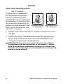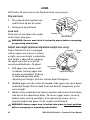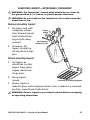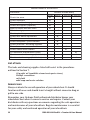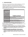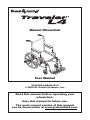
1
Manual Wheelchair User Manual 3F02-INS-LAB-RevE14 © 2009 GF Health Products, Inc. Read this manual before operating your wheelchair. Save this manual for future use. The most current version of this manual can be found online at www.grahamfield.com. CONTENTS 1 INTRODUCTION............................................................................... 4 2 IMPORTANT SAFETY PRECAUTIONS............................................... 6 WARNINGS................................................................................ 6 3 GETTING STARTED.......................................................................... 9 SETUP..................................................................................... 10 ADJUSTABLE BACK INSTALLATION.................................. 10 4 HANDLING TIPS............................................................................. 12 BALANCE................................................................................ 12 TRANSFER ACTIVITIES............................................................ 12 REACHING / BENDING............................................................. 13 RAMPS AND INCLINES............................................................ 14 CURBS AND STEPS................................................................. 15 5 ADJUSTMENTS.............................................................................. 16 REAR WHEELS, CASTERS, & ANTI-TIPPERS........................... 17 REAR WHEEL — STANDARD THREADED AXLE................ 17 REAR WHEEL — OPTIONAL QUICK-RELEASE AXLE......... 18 CASTERS........................................................................... 20 ANTI-TIPPERS................................................................... 21 ARMS...................................................................................... 22 FRONT RIGGING...................................................................... 23 FOOTREST—DETACHABLE, SWINGAWAY........................ 23 ELEVATING LEGREST—DETACHABLE, SWINGAWAY........ 25 CROSSBRACES....................................................................... 27 WHEEL LOCKS......................................................................... 28 6 TRANSPORTING OR STORING THE TRAVELER L4......................... 29 REASSEMBLY.......................................................................... 30 7 MAINTENANCE.............................................................................. 31 8 TROUBLESHOOTING...................................................................... 36 9 LIMITED WARRANTY..................................................................... 37 10 INDEX............................................................................................ 39 2 3F02-INS-LAB-RevE14 • Traveler L4 User Manual READ THIS MANUAL BEFORE OPERATING YOUR WHEELCHAIR GF Health Products, Inc. is not responsible for typographical errors. All illustrations, specifications, packaging and warranties contained in this document are based on the latest product information available at the time of printing. The most current product information, including the most current revision of this manual, can be found online at www.grahamfield.com. Graham-Field, Everest & Jennings, E&J, and Traveler are registered trademarks of GF Health Products, Inc. 3F02-INS-LAB-RevE14 • Traveler L4 User Manual 3 1 INTRODUCTION Important safety, operating, and maintenance instructions that warrant your attention are included in this user manual. Read the entire manual carefully before operating your new wheelchair, and refer to it as often as necessary to help maintain good performance standards. Consult your healthcare professional and GF Health Products, Inc. (“Graham-Field”) authorized distributor for assistance in developing and learning safe and effective techniques for performing your daily activities according to your individual physical abilities and needs, and to make certain that your wheelchair is properly prescribed and adjusted for your use. The safety precautions in this manual are general warnings intended to be used only as basic guidelines. You may find it necessary to develop your own methods for safely solving frequently encountered challenges. Again, consult your professional medical advisors for their recommendations about safety methods, and never hesitate to ask for their assistance. Your wheelchair should receive frequent, regularly scheduled maintenance, including an inspection of the mechanical parts, to ensure proper operation. Some suggested inspection procedures, troubleshooting procedures, and adjustment procedures are included in this manual. When it comes to service and repair, remember that your Graham-Field authorized distributor knows your wheelchair best. Thank you for choosing an Everest & Jennings product. The Traveler L4 is a manual, folding, lightweight wheelchair, suitable for frequent users who require a lightweight, portable wheelchair, fitted to their anatomy, without the need of customization or alteration to the center of gravity. The Traveler L4 is intended for indoor and/or outdoor use. The person performing adjustments on the Traveler L4 has the responsibility of making certain that the user can safely operate the wheelchair with the adjustments selected. This person must evaluate the user's ability, weight, physical condition, the environment in which the wheelchair will be used, and the terrain over which the wheelchair will travel. We recommend the use of anti-tippers at all times. 4 3F02-INS-LAB-RevE14 • Traveler L4 User Manual WARNING: When wheelchair is in use, anti-tippers must be installed in the downward position. Please note the following special statements, used throughout this manual, and their significance: WARNING: Indicates a potential hazard situation or unsafe practice that, if not avoided, could result in death or serious personal injury. CAUTION: Indicates a potential hazard situation or unsafe practice that, if not avoided, could result in minor or moderate personal injury. s NOTICE: Indicates a potential hazard situation or unsafe practice that, if not avoided, could result in product or property damage. Info: Provides application recommendations or other useful information to ensure that you get the most from your product. 3F02-INS-LAB-RevE14 • Traveler L4 User Manual 5 2 IMPORTANT SAFETY PRECAUTIONS IMPORTANT SAFETY PRECAUTIONS: ALWAYS FOLLOW THESE SAFETY PRECAUTIONS WHEN USING YOUR WHEELCHAIR. FAILURE TO DO SO COULD RESULT IN PERSONAL INJURY TO YOU OR OTHERS OR DAMAGE TO YOUR WHEELCHAIR. Safety requires the constant attention of the wheelchair user and the attendant. It is extremely important to learn and always use safe methods of performing basic daily activities. Always consult your healthcare professional to determine those methods most suitable for your individual abilities. Protect yourself and your wheelchair by having your Traveler L4 serviced regularly. Whenever any part of your Traveler L4 is not functioning properly, contact your Graham-Field authorized distributor immediately, as a hazardous situation could result, causing personal injury or damage to your wheelchair. ONLY EXCELLENT CONDITION IS ACCEPTABLE WHERE SAFETY IS CONCERNED. Periodic inspection, adjustment, and replacement of worn parts will provide many years of superb performance. WARNINGS WARNING: Traveler L4 maximum weight capacity is 16" seat depth: 250 lb (114 kg), EVENLY DISTRIBUTED. 18" seat depth: 300 lb (136 kg), EVENLY DISTRIBUTED. WARNING: Do not operate this wheelchair on streets or roadways. WARNING: Do not operate this wheelchair on hilly or rough terrain, sand, wet or icy surfaces, or surfaces with impaired traction. Ensure that pathway is clear of all obstacles. WARNING: Do not turn wheelchair while going downhill, as wheelchair could tip over. WARNING: Do not attempt inclines without anti-tippers installed in the downward position. Do not attempt any incline or decline greater than six degrees (10% grade, or one foot of rise or fall per ten feet of ramp length). 6 3F02-INS-LAB-RevE14 • Traveler L4 User Manual WARNING: This wheelchair does not offer seating or occupant restraint equivalent to the seat provided in a motor vehicle! To increase your safety while traveling in a motor vehicle, always transfer to the vehicle seat and use the restraint provided by the vehicle manufacturer. WARNING: Do not tie down or attach anything to the wheels. This could cause tipping and possibly result in injury or damage to the wheelchair. WARNING: The footplates' lowest point should clear the ground by at least 2 1/2 inches, to permit proper clearance of potential obstruction. WARNING: Doing a “wheelie” (tilting the wheelchair backward until it reaches its balance point) is dangerous and could result in personal injury to the user. WARNING: Do not stand or step on the footplates while transferring to or from your wheelchair. This could cause the wheelchair to tip or may cause personal injury or damage to your wheelchair. WARNING: Do not place your hands between seat rail and side panel. WARNING: Always engage wheel locks before transferring, using a wheelchair lift or using an elevator. WARNING: Ensure that wheelchair is on a stable, level surface and engage wheel locks before and during transfer. WARNING: Operate only with anti-tippers in place when leaning or tipping. When wheelchair is in use, anti-tippers must be installed in the downward position. WARNING: Do not lean over the top of the wheelchair back. This could cause the wheelchair to tip over. WARNING: To reduce the risk of tipping before leaning or reaching forward, sit back in the seat and rotate casters fully toward front of wheelchair. WARNING: Unauthorized modification or the use of nonEverest & Jennings replacement parts could change the structure of the wheelchair, void the warranty, and create a hazardous condition resulting in serious personal injury. 3F02-INS-LAB-RevE14 • Traveler L4 User Manual 7 WARNING: Do not lean on this wheelchair or use it as a walker—these are practices which could result in loss of balance and personal injury. WARNING: Do not use your wheelchair on escalators. WARNING: Wheel locks are not brakes. Do not use the wheel locks to slow down your wheelchair, or while the wheelchair is moving. Wheel locks are only intended to keep the wheelchair in place when it is at a complete stop. WARNING: Notice for California Customers- California Proposition 65 WARNING: This product contains a chemical known to the State of California to cause cancer and reproductive or developmental harm. WARNING: GF Health Products, Inc. specifically disclaims responsibility for any personal injury or property damage which may occur during any use which does not comply with federal, state, or local laws or ordinances. 8 3F02-INS-LAB-RevE14 • Traveler L4 User Manual 3 GETTING STARTED Please familiarize yourself with main components, identified in Traveler L4 illustration below. back upholstery push handle/ back post armpad arm rear wheel seat upholstery footrest handrim anti-tipper wheel lock crossbrace footplate frame caster wheel 3F02-INS-LAB-RevE14 • Traveler L4 User Manual caster housing caster fork 9 SETUP ADJUSTABLE BACK INSTALLATION (REFER TO THE FOLLOWING PICTURES) WARNING: Important: Read and understand these instructions before installing the Adjustable Back. Ensure the Adjustable Back is installed as described in the following paragraphs before use. If the Adjustable Back is not properly assembled, personal injury and/or property damage could result. The Adjustable Back includes: Quantity Description 1 Adjustable Back with back upholstery and 2 backposts 2 1/4" threaded knob 2 1/4" x 1 1/4" hex bolt 2 16" cable tie back upholstery backpost cable tie grommet backpost height adjustment holes threaded knob bolt seat upholstery frame rail frame see detail Adjustable Back pre-installation, right side (right arm, right rear wheel, and crossbraces not shown) Pre-installation detail 1. Insert backposts into frame sockets as shown above. 10 3F02-INS-LAB-RevE14 • Traveler L4 User Manual 2. Install bolts from outside of frame and secure with threaded knobs on inside of frame at desired height. Hand tighten. bolt cable tie see detail Adjustable Back installation, right side Installation detail 3. Install cable ties through back upholstery grommets and attach around frame rail as shown above. WARNING: Ensure both backposts are the same height and all parts of Adjustable Back are secured as instructed before use. 3F02-INS-LAB-RevE14 • Traveler L4 User Manual 11 4 HANDLING TIPS The Everest & Jennings Traveler L4 has been designed and engineered to perform as a stable and well balanced unit when used for its intended purpose. However, it is possible to tip the Traveler L4 over if it is used improperly. We urge you to learn the characteristics of your wheelchair. It is most important to learn safe methods to perform the daily activities basic to your lifestyle. Consult your medical professionals for assistance in developing the skills and proper techniques to perform all activities safely. BALANCE Proper balance is the key to maintaining the stability of your wheelchair. Reaching, bending, and transferring to or from a wheelchair will change the weight distribution and center of gravity of you and your wheelchair. When performing such activities, do so as instructed in the following paragraphs to avoid tipping the wheelchair. TRANSFER ACTIVITIES WARNING: Always ensure that the wheelchair is on a stable, level surface and engage wheel locks before transfer. WARNING: Do not step on the footplates; this could cause the wheelchair to tip. Fold them up, and either detach them, or swing them aside. WARNING: There is a critical moment when there is little or no seat platform beneath you. Take every precaution to reduce this unsupported distance before you attempt transfer. Transferring into or out of a wheelchair is a very difficult maneuver. Exercise extreme care when transferring without the aid of either an attendant or a patient lift. Consult your physician, nurse, or physical therapist for assistance in developing your individual technique. Make sure that the wheelchair is stabilized, and will not move or slide during the transfer. Take extra precaution to prevent tipping. Use good body mechanics to prevent personal injury. 12 3F02-INS-LAB-RevE14 • Traveler L4 User Manual REACHING / BENDING WARNING: Always turn the casters frontward to provide stability while reaching. If in doubt, ask for assistance or use a device that will extend your reach without requiring you to shift your weight. Although it is not recommended, you may find it occasionally necessary to lean or reach from your wheelchair. Consult with your healthcare professional for assistance in developing your personal safe reaching or moving techniques suited to your ability and restrictions. Forward or sideward WARNING: Do not attempt to reach objects if you are required to move forward in the seat. Do not attempt to retrieve objects from the floor if you must reach down between your knees. Do not shift your weight in the direction that you are reaching and/ or bending; this could cause the wheelchair to tip. 1. Maneuver the wheelchair as close as possible to the object you wish to reach. 2. Rotate both casters fully forward, go forward, and then back the wheelchair toward the object to swing the casters fully forward. 3. Engage both wheel locks. 4. Ensure that the casters are rotated fully forward before reaching. If not, repeat step 2. Backward WARNING: Do not engage the wheel locks while reaching or bending backward. Should your weight suddenly shift accidentally, it is better to roll in that direction than to tip over. WARNING: Do not lean over the back upholstery; this could cause the wheelchair to tip. 1. Maneuver the wheelchair as close as possible to the object; the rear wheels will limit how close you can get. 2. Rotate both casters fully forward, go forward, and then back the wheelchair toward the object to swing the casters fully forward. 3. Reach only as far as your arm will extend without changing your sitting position. If in doubt, reposition the wheelchair or ask for assistance. 3F02-INS-LAB-RevE14 • Traveler L4 User Manual 13 RAMPS AND INCLINES WARNING: During descent, the footplates' lowest point should be no closer to the ground than 2 1/2 inches to permit proper clearance. WARNING: Do not attempt inclines without anti-tippers installed in the downward position. Do not attempt any incline or decline of more than 6 degrees (10% grade, or one foot of rise or fall per ten feet of ramp length). WARNING: Do not use wheel locks to slow your descent. Attempting to use wheel locks is likely to result in accidental locking that could cause the wheelchair to stop abruptly, suddenly pitch forward, or tip sideways. WARNING: Avoid changing direction while descending a ramp or incline, as this could cause instability. Most people are capable of negotiating short inclines without assistance, depending upon upper body strength, endurance, and the degree of incline. Know your own capabilities and limitations in terms of strength and endurance before attempting to negotiate an incline or decline. Practice with an attendant or healthcare professional first before attempting any inclines, declines curbs or ramps. Always inspect the ramp for hazards such as holes, slippery or uneven surfaces, etc. before starting up or down. If you can not see the entire ramp, ask someone to inspect it for you. Ascent Lean the upper part of your body slightly forward as you ascend the incline. If it becomes necessary to stop on the incline, avoid any abrupt or sudden forward movement as you resume climbing, this could cause tipping. Descent Always face forward when going down a ramp, but do not lean forward; this could cause tipping. Lean slightly backward to increase stability. It is critical to keep the wheelchair under control at all times. Descent should be made slowly and safely by grasping the handrims; however, use care, as friction heat will be generated. We recommend the use of gloves to reduce the effects of friction heat, but going slower is a better alternative. 14 3F02-INS-LAB-RevE14 • Traveler L4 User Manual CURBS AND STEPS Curbs, steps and stairways are dangerous obstacles that confront the wheelchair user. When you encounter curbs, find a way around, or use the ramps now available in most locations. If you encounter steps and there is no ramp available, avoid the steps by utilizing the disabled designated elevators now required in most locations. WARNING: Never attempt to negotiate steps, stairs or escalators in your Traveler L4. 3F02-INS-LAB-RevE14 • Traveler L4 User Manual 15 5 ADJUSTMENTS The Traveler L4 offers several adjustments to make it easier and more comfortable to drive. Section 7, MAINTENANCE, offers preventive maintenance suggestions for keeping your wheelchair in excellent condition; ensure that all components are in excellent condition before adjusting. The following are recommended methods; after a few adjustments, you may develop your own. Always consult your Graham-Field authorized distributor for assistance. The person performing adjustments on the Traveler L4 has the responsibility of making certain that the user can safely operate the wheelchair with the adjustments selected. This person must evaluate the user's ability, weight, physical condition, the environment in which the wheelchair will be used, and the terrain over which the wheelchair will travel. All adjustments and their page locations are referenced in the index at the end of this manual. Specific tools needed to perform each adjustment are identified in adjustment directions. A complete list of tools needed to perform all adjustments in this section follows: Phillips screwdriver Two 5/8" wrenches M13 wrench M11 wrench M6 hex key 16 3F02-INS-LAB-RevE14 • Traveler L4 User Manual REAR WHEELS, CASTERS, & ANTI-TIPPERS Rear wheels, casters, and anti-tippers are grouped because rear axle mounting position determines caster axle mounting position and antitipper adjustment height. Using the correct combination of rear axle and caster mounting positions maintains the correct alignment of the wheelchair. We recommend that you do not replace or adjust rear wheel, caster, or anti-tipper components yourself, since special tools and training are required. Please contact your Graham-Field authorized distributor when your rear wheels or casters need adjustment. REAR WHEEL — STANDARD THREADED AXLE We recommend that you do not replace or adjust standard threaded-axle rear wheel components yourself, since special tools and training are required. Please contact your Graham-Field authorized distributor when standard rear wheels with standard threaded axles need adjustment. 3F02-INS-LAB-RevE14 • Traveler L4 User Manual 17 REAR WHEEL — OPTIONAL QUICK-RELEASE AXLE see Axle Detail quick-release axle rear wheel mounting position for 20" seat height quick-release push button locking button Axle Detail, rear wheel installed As shown above, the rear axle is mounted in the sideframe's bottom wheel bushing for 20" seat height. For 18" seat height, mount the rear axle in the top wheel bushing. Remove rear wheel — optional quick-release axle Depress the quick-release push button in the rear wheel hub and pull the wheel straight out, away from the wheelchair. 18 3F02-INS-LAB-RevE14 • Traveler L4 User Manual Install rear wheel — optional quick-release axle Depress the quick-release push button in the rear wheel hub and insert into axle sleeve. WARNING: When reassembling the wheelchair after removing the rear wheels, ensure the rear axles are locked in place (check that locking buttons extend completely, and rear wheels spin freely but can't be pulled off), to prevent wheels from falling off. WARNING: Perform your rear wheel and caster adjustments in accordance with the instructions in this manual — failure to do so could create a hazardous situation, or a situation in which the caster housings are not perpendicular to the ground, making steering difficult. WARNING: Wheel locks may no longer fit after adjusting rear wheel height. See wheel lock adjustment section to adapt wheel locks to fit after adjusting rear wheel height. WARNING: Anti-tipper height may not be appropriate after adjusting rear wheel height. See anti-tipper adjustment section to adapt anti-tipper rollers to fit after adjusting rear wheel height. 3F02-INS-LAB-RevE14 • Traveler L4 User Manual 19 CASTERS Adjust caster mounting position Two 5/8" wrenches Using the correct combination of rear axle mounting position and caster mounting position maintains the correct alignment of the wheelchair. As shown at right, the caster axle is mounted in the bottom caster fork hole for 20" seat height, and in the top caster fork hole for 18" seat height. caster axle caster axle mounting position mounting position 20" seat height 18" seat height 1. Remove caster wheel: Use two 5/8" wrenches to remove the caster axle bolt. 2. Install caster wheel: Thread the bolt through the fork and wheel. Ensure that fasteners are secure. The wheel should spin freely, coming to a gradual stop, but without play. WARNING: Perform your rear wheel and caster adjustments in accordance with the instructions in this manual — failure to do so could create a hazardous situation, or a situation in which the caster housings are not perpendicular to the ground, making steering difficult. 20 3F02-INS-LAB-RevE14 • Traveler L4 User Manual ANTI-TIPPERS Adjust anti-tipper roller position Anti-tippers must be mounted in the appropriate position for each seat height. As shown at right, the anti-tipper locking button protrudes from the top roller tube hole for 20" seat height, and from the bottom roller tube hole for 18" seat height. locking button roller tube anti-tipper tube anti-tipper position 20" seat height anti-tipper position 18" seat height 1. Depress the anti-tipper roller tube locking button to free the roller tube to slide over the anti-tipper tube. 2. Slide roller tube to appropriate position until locking button protrudes completely from hole. WARNING: Ensure anti-tipper rollers are mounted in the appropriate position for each seat height, as shown above. WARNING: Ensure anti-tipper locking buttons protrude completely from roller tube holes. 3F02-INS-LAB-RevE14 • Traveler L4 User Manual 21 ARMS All Traveler L4 arms feature the flip-back latch (see picture). Flip arm back 1. Press top of latch against arm and lift arm up out of socket. latch arm 2. Swing arm up and back. Lock arm Push front of arm down into socket until it locks into place. socket flip arm back WARNING: Ensure arm latch is locked in place before occupying or operating wheelchair. Adjust arm height (optional adjustable-height arm only) If your Traveler L4 arm is equipped with an upper arm release as shown at right, your arm height is adjustable. Arm height is adjusted by engaging the upper arm release in one of several predrilled holes. To adjust: armpad upper arm upper arm 1. Pull upper arm release until release it unlocks, freeing upper arm adjust arm height to move up and down. To keep in unlocked position while adjusting arm height, turn the release knob 90 degrees. 2. Holding upper arm by center of armpad, slide upper arm up or down to desired height. Ensure both front and back of armpad are at the same height. 3. Rotate release knob back to former position and ensure that it locks into one of the adjustment holes. To ensure upper arm is securely locked, move arm up and down; if no movement occurs, arm is properly locked into place; if not, readjust until locked. WARNING: Ensure upper arm is locked into place in level position before occupying or operating wheelchair. 22 3F02-INS-LAB-RevE14 • Traveler L4 User Manual FRONT RIGGING FOOTREST—DETACHABLE, SWINGAWAY WARNING: The footplates' lowest point should be no closer to the ground than 2 1/2 inches, to permit proper clearance. WARNING: Do not stand on the footplates; this could cause the wheelchair to tip. Remove footrest 1. To release lock, pull swingaway release lever forward, toward front of wheelchair. Footrest will swing outward. 2. To remove, lift footrest straight up off wheelchair hinge pins. hinge plate swingaway release lever Attach footrest 1. Set footrest on wheelchair (so that footrest hinge plates engage wheelchair hinge pins). 2. Swing footrest inward. 3. Ensure that swingaway release lever is locked in a rearward position, toward back of wheelchair. remove footrest (left shown) WARNING: Ensure footrests are locked in place before occupying or operating wheelchair. 3F02-INS-LAB-RevE14 • Traveler L4 User Manual 23 Adjust footplate extension length 1. See picture at right. Loosen latch to free footplate extension inside hanger. 2. Press down on the locking button and adjust the footplate to the desired length. Ensure that the locking button is completely extended and securely fastened in the adjustment hole. 3. Fasten latch to secure footplate extension inside hanger. 4. Repeat steps 1-3 for the other footplate extension. locking button hanger adjustment holes latch footplate footplate extension, adjust length 5. Ensure both footplate extensions are securely fastened and minimum ground clearance is 2 1/2 inches. WARNING: Ensure footplates are securely fastened before occupying or operating wheelchair. 24 3F02-INS-LAB-RevE14 • Traveler L4 User Manual ELEVATING LEGREST—DETACHABLE, SWINGAWAY WARNING: The footplates' lowest point should be no closer to the ground than 2 1/2 inches, to permit proper clearance. WARNING: Do not stand on the footplates; this could cause the wheelchair to tip. Remove elevating legrest 1. To release lock, pull swingaway release lever forward, toward front of wheelchair. Legrest will swing outward. hinge plate swingaway release lever 2. To remove, lift legrest straight up off wheelchair hinge pins. Attach elevating legrest 1. Set legrest on wheelchair (so that legrest hinge plates engage wheelchair hinge pins). 2. Swing legrest inward. remove elevating legrest 3. Ensure legrest is locked in place and swingaway release lever is locked in a rearward position, toward back of wheelchair. WARNING: Ensure legrests are locked in place before occupying or operating wheelchair. 3F02-INS-LAB-RevE14 • Traveler L4 User Manual 25 ADJUST LEGREST ELEVATION CAUTION: It is possible to RAISE the elevating legrest without moving the legrest release lever. As a safety feature, however, in order to LOWER the elevating legrest you must move the legrest release lever. This is to prevent the legrest from accidentally dropping while the user’s leg is elevated. WARNING: Ensure elevating legrests are locked in place before occupying or operating wheelchair. Raise elevating legrest Slowly rotate the legrest up to the desired position. Ensure elevating legrest is locked in position. legrest release lever Lower elevating legrest 1. To allow the elevating legrest to lower without dropping suddenly, support its weight and move the release lever forward. 2. Slowly lower elevating legrest to desired position. legrest panel 3. Release lever. Ensure elevating legrest is locked in position before letting go of legrest. adjust legrest Adjust elevating legrest panel position The legrest panel can be rotated up and out of the way. Refer to picture above. 1. To adjust panel, hold the panel and rotate it upward. 2. To return panel to position, hold the panel and rotate downward. The panel will stop at the proper position. WARNING: Ensure that legrest panels are locked in place before occupying or operating wheelchair. 26 3F02-INS-LAB-RevE14 • Traveler L4 User Manual Adjust legrest footplate extension length See Adjust footplate extension length in Footrest—Detachable, Swingaway section. CROSSBRACES Tighten crossbraces M13 wrench, M6 hex key Check the crossbraces to ensure that the bolt and nut securing both crossbraces in the center of the wheelchair are secure (crossbraces should be loose enough to fold easily, yet snug enough to take up excess play). Use an M13 wrench and M6 hex key to tighten. 3F02-INS-LAB-RevE14 • Traveler L4 User Manual 27 WHEEL LOCKS Adjust wheel locks M11 wrench 1. Use an M11 wrench to loosen the adjustment bolt until the wheel lock slides on the frame. 2. Place the wheel lock in the locked position and slide it into contact with the tire. 3. Place the wheel lock in the unlocked position and slide it 3/8" closer to the tire. right rear wheel wheel lock adjustment bolt right front frame wheel lock shown unlocked 4. Use an M11 wrench to tighten the adjustment bolt and engage the wheel lock to check the fit. The wheel lock should indent the tire at least 3/8". 5. Repeat steps 1-4 for other wheel lock. Tighten the adjustment bolts securely to eliminate wheel lock movement on frame. WARNING: Ensure wheel locks are adjusted so that they lock in place appropriately before occupying or operating wheelchair. 28 3F02-INS-LAB-RevE14 • Traveler L4 User Manual 6 TRANSPORTING OR STORING THE TRAVELER L4 WARNING: This wheelchair does not offer seating or occupant restraint equivalent to the seat provided in a motor vehicle! To increase your safety while traveling in a motor vehicle, always transfer to the vehicle seat and use the restraint provided by the vehicle manufacturer. The Traveler L4 can easily be folding for transport or storage: 1. Detach front rigging from wheelchair. 2. Remove the seat cushion, if so equipped. 3. Fold the wheelchair: pull up sharply on the seat sling at front and rear center at the same time. To fold wheelchair completely, tip the wheelchair sideways (so wheel won't drag) and press sides together. Info: If your Traveler L4 is equipped with quick-release rear axles, you may also remove the rear wheels before transportation or storage. To remove the rear wheels, follow the instructions in the Rear Wheel — Optional Quick-Release Axle section of 5 Adjustments. For reassembly, see the following page. 3F02-INS-LAB-RevE14 • Traveler L4 User Manual 29 REASSEMBLY 1. Push down with even pressure on seat rails on both sides. WARNING: Do not place your hand between seat rail and side panel. 2. Push again if seat tubes are not positioned directly upon front seat rail / arm cradles as shown below (arm not shown). right front seat rail right front seat rail seat rail & arm cradle seat rail & arm cradle not locked locked correct position 3. Attach footrests or legrests to wheelchair. 4. Reinstall the seat cushion, if so equipped. WARNING: When reassembling the wheelchair, ensure that seat is completely open. If not, wheelchair is unsafe to occupy. WARNING: Ensure that footrests or legrests are locked in place before occupying or operating wheelchair 30 3F02-INS-LAB-RevE14 • Traveler L4 User Manual 7 MAINTENANCE Protect your E&J Traveler L4 by having it serviced regularly. Proper care and maintenance are essential to keep your wheelchair in safe working condition. Periodic inspection, adjustment, and replacement of worn parts will provide many years of superb performance. When you believe that a component or part of your Traveler L4 is not functioning properly, contact your Graham-Field authorized distributor immediately, as a potentially hazardous condition could result. Only excellent condition is acceptable where safety is concerned. Service manual There is no service manual for the Traveler L4. Please contact your Graham-Field authorized distributor with service questions not answered by this manual. Info: We recommend that you have a Graham-Field authorized distributor perform a six month maintenance check, as the distributor may find and correct a problem which might otherwise go undetected and eventually cause more serious problems and/or personal injury. Do-it-yourself maintenance You can do many of the scheduled maintenance tasks yourself, if you have mechanical ability and a few basic tools. Refer to the maintenance schedule on the next page for the recommended regularity of each procedure. If any maintenance procedure is not clear to you, ask your Graham-Field authorized distributor for assistance. s NOTICE: Improper maintenance can cause operating problems and may affect your warranty. WARNING: Unauthorized modification or the use of nonEverest & Jennings replacement parts could change the structure of the wheelchair, void the warranty, and create a hazardous condition resulting in serious personal injury. 3F02-INS-LAB-RevE14 • Traveler L4 User Manual 31 MAINTENANCE SCHEDULE Procedure Check tire wear Check handrims Check wheel lock engagement Check anti-tippers (optional) Wipe off frame with soft cloth Check handgrips Check upholstery Check rear wheel adjustment Check arms Check backposts / push handles Check footrests / elevating legrests Clean frame Check caster stem rotation GF distributor maintenance check Check rear wheel bearings (distributor) Check caster bearings (distributor) Perform at least every Week Month 3 Months 6 Months ✔ ✔ ✔ ✔ ✔ ✔ ✔ ✔ ✔ ✔ ✔ ✔ ✔ ✔ ✔ ✔ List of tools The tools and cleaning supplies listed will assist in the procedures outlined in Section 7. 30 weight oil (available at most auto parts stores) Phillips screwdriver soft cloth mild soap and water solution General care Always evaluate the overall operation of your wheelchair. It should function with ease and should travel straight without excessive drag or pull to one side. Remember, your Graham-Field authorized distributor knows your wheelchair best when it comes to service and repairs. Contact your distributor with any questions or concerns regarding the safe operation and maintenance of your wheelchair. Regular maintenance is essential for your safety and continued operation of your wheelchair. 32 3F02-INS-LAB-RevE14 • Traveler L4 User Manual Check tire wear Examine tires at least once a week for surface wear and cracks and replace them as needed. Replace polyurethane tires when they become loose on the rims or cracks appear. Check handrims Check handrims at least once a week. Inspect each handrim for rough or sharp edges and, if any are found, replace handrims immediately. Ensure that all hardware is properly aligned and secure. Check wheel lock engagement Check wheel lock engagement at least once a week. See Adjust wheel locks in Section 5 to adjust wheel lock engagement. If a wheel lock is worn or damaged, replace it immediately. Inspect the hardware for looseness or signs of wear. Ensure the locking mechanism operates smoothly. The locking assembly should be tight enough so that the wheel can not rotate or the lock slip. Check that the locking shoe does not press against the tire when in the unlocked position. Excessive force should not be required to either engage or release wheel locks. Oil the wheel lock pivot points with one or two drops of 30 weight oil. Remove excess oil and dirt. Check anti-tippers Check the anti-tippers at least once a week. Ensure that the anti-tippers are securely fastened and properly positioned. WARNING: When wheelchair is in use, anti-tippers must be installed in the downward position. Check handgrips Check handgrips at least once a week. Ensure they are not ripped; ensure they are tight and securely fastened. 3F02-INS-LAB-RevE14 • Traveler L4 User Manual 33 Check upholstery Check upholstery at least once a month. Inspect for rips, tears and worn spots. Ensure that all upholstery-attaching screws are present, properly aligned, and well-secured. Use a Phillips screwdriver to tighten upholstery mounting screws. Check attaching screws for sharp edges or stripped screws, and replace if found. WARNING: Worn or torn upholstery, or upholstery with loose hardware, must be replaced immediately. It may not support body weight. Check rear wheel adjustment Inspect the wheels at least once a month. Check alignment by elevating the rear of the wheelchair on a stable object until the rear wheels clear the ground, or placing the wheelchair upside down in a stable position such that the wheels can spin freely. Spin the wheels; there should be no wobble or sideplay, and the wheels should spin freely without binding. The bearings should be clean and rotate smoothly. Check rim sideplay to verify that bearings are not too loose. If there is a problem, contact your Graham-Field authorized distributor. If adjustment is required, this should be done by your distributor only. Check arms Check arms at least once a month. Inspect for sharp edges or cracks which could weaken the arm, and replace if found. Ensure all attaching screws are present and tight. Use a Phillips screwdriver to tighten armpad mounting screws. Check for burrs on the screw heads and replace if found. Ensure that screws do not extend into the padding. Confirm that posts at base of arm fit correctly in the sockets, snug but not binding. Adjustable height arms: Confirm fit in the upper telescoping portion, verify positive locking at each arm height position, and confirm operation of upper arm release. Check backposts / push handles Check backposts at least once a month. Ensure that all mounting hardware is securely fastened and that the backposts are not bent or damaged. Contact your Graham-Field authorized distributor if you observe cracking or peeling paint or plating. 34 3F02-INS-LAB-RevE14 • Traveler L4 User Manual Check footrests & elevating legrests Check footrests and legrests at least once a month. Inspect the locking mechanisms to confirm sure fit. Check for cracks, burrs, or sharp edges, and replace if found. Ensure that the footrest or legrest will automatically lock securely in place and will not accidentally unlock. If equipped with heel loops, ensure the anchor bolts are tight and secure. Cleaning your Traveler L4 Wipe off the frame frequently, at least once a week, using a soft cloth. Dry the wheelchair immediately if exposed to moisture. Clean the frame every three months with a mild soap and water solution. The frame does not need to be waxed. Do not use solvents, abrasive waxes, caustic chemicals or spray silicone. Never use abrasive cleansers; they could scratch the finish. Never use steam or high pressure cleaners. Clean upholstery and plastic components at least once a month with a mild soap and water solution. Check casters Check the caster stems for proper rotation at least every three months. The caster fork must swivel freely to facilitate steering and handling. Adjusting the stem nut varies the amount of force required to turn the caster. If the nut is too loose, the caster will flutter or shimmy; if the nut is too tight, the wheelchair will be difficult to steer. If the caster stem requires adjustment, or the stem bearings require replacement, contact your Graham-Field authorized distributor. Ensure that stems are firmly attached to forks, and that forks and stems are not bent. Evaluate all threads, locking nuts and bearings. Check wheel bearings Have your Graham-Field authorized distributor check caster and rear wheel axle bearings at least every six months. 3F02-INS-LAB-RevE14 • Traveler L4 User Manual 35 8 TROUBLESHOOTING Continual use of your Traveler L4 necessitates maintenance, especially if the factory-set adjustments have been altered. The following troubleshooting guide lists several common problems that may occur, and offers corrective actions for each. If you are unsure of the solution or unable to diagnose the problem, do not hesitate to ask your Graham-Field authorized distributor for assistance. looseness in wheelchair squeaks / rattles caster flutter sluggish turning chair veers left chair veers right SYMPTOM PROBABLE CAUSE AND CORRECTIVE ACTION Nuts and / or bolts may be loose. If so, tighten. Bolts should be snug. Rear wheels and / or casters may be adjusted improperly. Ensure that both rear wheels are mounted in identical positions, and that casters are mounted in identical positions. Caster stem(s) may be adjusted improperly. See distributor to correct adjustment. Info: Use only Everest & Jennings replacement parts. A Traveler L4 parts catalog is available at www.grahamfield.com to assist in the ordering of parts. CAUTION: A complete inspection of your wheelchair, including maintenance, servicing and safety checks, should be performed by a Graham-Field authorized distributor at least every six months. WARNING: Unauthorized modification or the use of nonEverest & Jennings replacement parts could change the structure of the wheelchair, void the warranty, and create a hazardous condition, which could result in serious personal injury. 36 3F02-INS-LAB-RevE14 • Traveler L4 User Manual 9 LIMITED WARRANTY SCOPE OF WARRANTY GF Health Products, Inc. (“GF”) warrants to the original purchaser only that it will replace or repair components, at GF’s sole discretion, that are defective in material or workmanship under normal use and service. All warranties are conditioned upon the proper use of the products strictly in accordance with good commercial practice and applicable GF instructions and manuals, including proper use and maintenance. To the extent that a component is warranted by a third party, GF conveys all of its rights under that warranty to the original purchaser, to the extent permitted. This limited warranty shall only apply to defects that are reported to GF’s customer service team within the applicable warranty period and which, upon examination by GF or its authorized representative, prove to be a warranty item. This limited warranty is not transferable. The warranted components and time period are set forth below: Sideframes and crossbraces: . . . . . . . . . . . . . . . . . . . . . five years Wheels, handrims, front rigging, forks: . . . . . . . . . . . . . one year All other durable components not listed above: . . . . . six months The applicable warranty period shall commence from date of shipment to the original customer, unless there is an expiration date on the component in which case the warranty shall expire on the earlier of warranty period or the expiration date. OBTAINING WARRANTY SERVICE A GF Customer Service Representative must authorize warranty service. Please contact the GF Customer Service department by calling 678-291-3207, sending a fax request to 770-368-2386 or by e-mailing a request to [email protected]. Specific directions will be provided by the Customer Service Representative. Failure to abide by the specific directions will result in denial of the warranty claim. EXCLUSIONS The warranty does not cover and GF shall not be liable for the following: 1) Defects, damage, or other conditions caused, in whole or in part, by misuse, abuse, negligence, alteration, accident, freight damage, tampering or failure to seek and obtain repair or replacement in a timely manner; 2) Products which are not installed, used, or properly cleaned and maintained as required in the official manual for the applicable product; 3) Products considered to be of a non-durable nature including, but not limited to: casters, filters, fuses, gaskets, lubricants, and charts; 4) Accessories or parts not provided by GF; 5) Charges by anyone for adjustments, repairs, replacement parts, installation or other work performed upon or in connection with such products which are not expressly authorized in writing, in advance, by GF; 6) Any labor or shipping charges incurred in the replacement part installation or repair; 7) Costs and expenses of regular maintenance and cleaning; and 8) Representations and warranties made by any person or entity other than GF. 3F02-INS-LAB-RevE14 • Traveler L4 User Manual 37 ENTIRE WARRANTY, EXCLUSIVE REMEDY AND CONSEQUENTIAL DAMAGES DISCLAIMER THIS WARRANTY IS GF’S ONLY WARRANTY AND IS IN LIEU OF ALL OTHER WARRANTIES, EXPRESS OR IMPLIED. GF MAKES NO IMPLIED WARRANTIES OF ANY KIND INCLUDING ANY IMPLIED WARRANTIES OF MERCHANTABILITY OR FITNESS FOR A PARTICULAR PURPOSE. IF ANY MODEL OR SAMPLE WAS SHOWN TO THE CUSTOMER, SUCH MODEL OR SAMPLE WAS USED MERELY TO ILLUSTRATE THE GENERAL TYPE AND QUALITY OF THE PRODUCT AND NOT TO REPRESENT THAT THE PRODUCT WOULD NECESSARILY CONFORM TO THE MODEL OR SAMPLE IN ALL RESPECTS. THIS WARRANTY IS LIMITED TO THE REPAIR OR REPLACEMENT OF THE DEFECTIVE PARTS. GF SHALL NOT BE LIABLE FOR AND HEREBY DISCLAIMS ANY DIRECT, SPECIAL, INDIRECT, INCIDENTAL, EXEMPLARY OR CONSEQUENTIAL DAMAGES, INCLUDING, BUT NOT LIMITED TO: DAMAGES FOR LOSS OF PROFITS OR INCOME, LOSS OF USE, DOWNTIME, COVER, OR EMPLOYEE OR INDEPENDENT CONTRACTOR WAGES, PAYMENTS AND BENEFITS. The warranties contained herein contain all the representations and warranties with respect to the subject matter of this document, and supersede all prior negotiations, agreements and understandings with respect thereto. The recipient of this document hereby acknowledges and represents that it has not relied on any representation, assertion, guarantee, warranty, collateral contract or other assurance, except those set out in this document. For additional information on this product or this warranty, please contact a GF Customer Service Representative. NOTES: 1) Additional terms and conditions may apply. 2) Freight claims must be notated on the Bill of Lading and must be made with immediacy. The ICC regulations govern specific requirements for freight claims. Failure to abide by those regulations may result in a denial of the freight claim. GF will assist you in filing the freight claim. 3) Claims for any short shipment must be made within thirty (30) days of the invoice date. GF Health Products, Inc. 2935 Northeast Parkway Atlanta, GA 30360 Tel 770-368-4700 Fax 770-368-2386 www.grahamfield.com 38 3F02-INS-LAB-RevE14 • Traveler L4 User Manual 10INDEX A Adjustable back installation 10 Adjustments 16 Anti-tippers, check 33 Arm, flip back 22 Arm height, adjust 22 Arm, lock 22 Arms, check 34 B Backposts, check 34 Balance 12 C Caster stems, check 35 CAUTION statement, significance 5 Cleaning your Traveler L4 35 Crossbraces, tighten 27 Curbs and steps 15 E Elevating legrest, attach 25 Elevating legrest elevation, adjust 26 Elevating legrest, lower 26 Elevating legrest, raise 26 Elevating legrest, remove 25 Elevating legrest—detachable, swingaway 25 Elevating legrest elevation, adjust 26 F Footrest, attach 23 Footrest, remove 23 Footrest—detachable, swingaway 23 G Getting started 9 H Handling tips 12 Handrims, check 33 I Info statement, significance 5 Install rear wheel — quick-release axle (optional) 19 Introduction 4 3F02-INS-LAB-RevE14 • Traveler L4 User Manual M Maintenance 31 N NOTICE statement, significance 5 R Ramps and Inclines 14 Reaching / bending 13 Rear wheel adjustment, check 34 Rear wheel quick-release axle, install (optional) 19 Rear wheel quick-release axle, remove (optional) 17,?18 Rear wheels 17 S Safety precautions 6 Setup 10 Storing the Traveler L4 29 T Tires, check 33 Tools, for adjustment, list 16 Tools, for maintenance, list 32 Transfer activities 12 Transporting the Traveler L4 29 Traveler L4, illustration 9 Troubleshooting 36 U Upholstery, check 34 W WARNINGS 6 WARNING statement, significance 5 Warranty, limited 37 Wheel bearings, check 35 Wheel lock engagement, check 33 Wheel locks, adjust 28 39 Manufactured for: GF Health Products, Inc. 2935 Northeast Parkway Atlanta, Georgia 30360 USA tel: 770-368-4700 fax: 770-368-2386 www.grahamfield.com Made in China