1
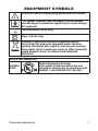
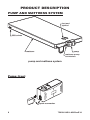
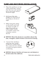
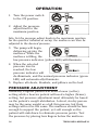
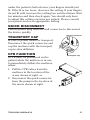
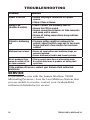
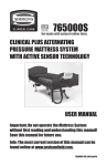
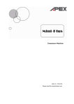
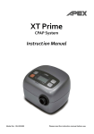
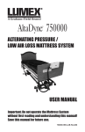
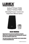
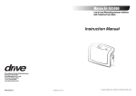
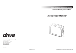
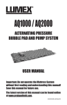
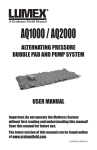
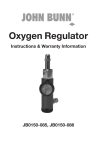
750000
ALTERNATING PRESSURE /
LOW AIR LOSS MATTRESS SYSTEM
USER MANUAL
Important: Do not operate the Mattress System
without first reading and understanding this manual!
Save this manual for future use.
Info: The most current version of this manual can be
found online at www.grahamfield.com.
750000-INS-LAB-RevE14
CONTENTS
INTRODUCTION ...................................................................................... 3
INTENDED USE OF THIS DEVICE ................................................... 3
CONTRAINDICATION ................................................................ 3
IMPORTANT SAFETY PRECAUTIONS .................................................. 4
DANGER ........................................................................................... 4
WARNING .......................................................................................... 5
NOTICE ............................................................................................. 6
EQUIPMENT SYMBOLS ......................................................................... 7
PRODUCT DESCRIPTION ...................................................................... 8
PUMP AND MATTRESS SYSTEM .................................................... 8
PUMP: FRONT............................................................................ 8
PUMP: REAR .............................................................................. 9
PUMP: TOP PANEL .................................................................... 9
INSTALLATION ...................................................................................... 11
UNPACKING.................................................................................... 11
PUMP AND MATTRESS INSTALLATION ....................................... 12
OPERATION .......................................................................................... 14
PRESSURE ADJUSTMENT ............................................................ 14
QUICK DISCONNECT ..................................................................... 15
TRANSPORT CAP .......................................................................... 15
CPR FUNCTION .............................................................................. 15
MAINTENANCE ..................................................................................... 16
CLEANING ...................................................................................... 16
GENERAL MAINTENANCE ............................................................ 16
FUSE REPLACEMENT............................................................. 17
AIR FILTER REPLACEMENT ................................................... 17
STORAGE ....................................................................................... 17
TROUBLESHOOTING ........................................................................... 18
SERVICE ......................................................................................... 18
SPECIFICATIONS.................................................................................. 19
LIMITED WARRANTY ........................................................................... 20
APPENDIX A: EMC INFORMATION ..................................................... 21
GF Health Products, Inc. is not responsible for typographical errors. All
illustrations, specifications, packaging and warranties contained in this
document are based on the latest product information available at the
time of printing. The most current product information, including the most
current revision of this manual, can be found online at www.grahamfield.com.
Graham-Field, Lumex, and AltaDyne are registered trademarks of GF Health
Products, Inc.
2
750000-INS-LAB-RevE14
INTRODUCTION
Use this manual for set-up and operation of the Lumex
AltaDyne 750000 Alternating Pressure / Low Air Loss
Mattress System. Read all instructions before using the
mattress system. Save this manual for future reference.
INTENDED USE OF THIS DEVICE
The intended use of the Lumex AltaDyne 750000
Alternating Pressure / Low Air Loss Mattress System is:
• The treatment of pressure ulcers while optimizing user
comfort.
• Pain management as prescribed by a physician.
• As described above, in either a homecare or long term
care setting.
Contraindication
WARNING: DO NOT use this product in the presence
of flammable anesthesia. There is a possible fire
hazard when this product is used with certain oxygen
delivery equipment.
Use nasal cannula, face mask, or 1/2 length oxygen
tent to deliver oxygen in the presence of this product.
DO NOT use a full length oxygen tent that extends
past the top surface of the mattress with this product.
750000-INS-LAB-RevE14
3
IMPORTANT SAFETY PRECAUTIONS
The safety statements presented in this chapter refer
to the basic safety information that should be observed
by those using the Alternating Pressure / Low Air Loss
Mattress System. There are additional safety statements in
other chapters or sections, which may be the same as or
similar to the following, or specific to the operations.
DANGER: Indicates an imminent hazard situation
that, if not avoided, will result in death or serious
injury.
WARNING: Indicates a potential hazard situation or
unsafe practice that, if not avoided, could result in
death or serious injury.
CAUTION: Indicates a potential hazard or unsafe
practice that, if not avoided, could result in minor or
moderate personal injury.
s NOTICE: Indicates a potential hazard or unsafe
practice that, if not avoided, could result in product
or property damage.
Info: Provides application recommendations or other useful
information to ensure that you get the most from your
product.
DANGER
To reduce the risk of electrocution:
DANGER: Always unplug this product immediately
after using.
DANGER: Do not use this product while bathing.
DANGER: Do not place or store this product where it
can fall or be pulled into a tub or sink.
DANGER: Do not place this product in or drop into
water or other liquid.
DANGER: Do not reach for a product that has fallen
into water. Unplug it immediately.
4
750000-INS-LAB-RevE14
WARNING
To reduce the risk of burns, electrocution, fire, or
personal injury:
WARNING: Do not leave this product unattended
when plugged in.
WARNING: Always use close supervision when this
product is used by, on, or near children or those who
require close supervision.
WARNING: Use this product only as intended
and described in this manual. Do not use
attachments or accessories not recommended by
GF Health Products, Inc.
WARNING: Never operate this product if:
a) it has a damaged cord or plug,
b) it is not working properly,
c) it has been dropped or damaged, or
d) it has been dropped into water.
Return the product to your Graham-Field authorized
distributor.
WARNING: Keep the cord away from heated surfaces.
WARNING: Never drop or insert any object into any
opening or hose.
WARNING: Never block the air openings of this
product or place it on a soft surface, such as a bed or
couch, where the openings may be blocked. Keep the
air opening free of lint, hair, and other similar particles.
WARNING: Connect this product only to a properly
grounded power outlet.
WARNING: Maximum patient weight capacity for this
product is 350 lb (159 kg), EVENLY DISTRIBUTED.
WARNING: Notice for California Customers- California
Proposition 65 WARNING: This product contains a
chemical known to the State of California to cause
cancer and reproductive or developmental harm.
750000-INS-LAB-RevE14
5
WARNING: Patient entrapment with bed side rails
may cause injury or death. The bed frame and its
components, including the mattress, bed side rails,
head and foot board, bedding, and any accessories
added to the bed, can all affect the risk of entrapment.
Thorough patient assessment and monitoring are
necessary to reduce the risk of entrapment, including
establishing whether the use of a bed rail is in the
best interest of the patient. Read and understand the
User Manual before using this equipment. GF Health
Products, Inc. product manuals are available online at
www.grahamfield.com.
Visit the FDA's Bed Safety page at www.fda.gov to
learn more about the risks of entrapment. It is the
responsibility of the facility and provider to be in
compliance with these guidelines. Refer to user
manuals for beds and rails for additional product
safety information.
After any adjustment, repair or service, and before
use, ensure all attaching hardware is securely
tightened. Bed rails with dimensions different
than the original equipment specified by the bed
manufacturer may not be interchangeable and may
result in entrapment or other injury.
NOTICE
s NOTICE: The pump can be used only with the
accompanying mattress. Do not use it for any other
purpose.
6
750000-INS-LAB-RevE14
EQUIPMENT SYMBOLS
Attention! Consult accompanying documents (this manual)
“BF”symbol: Indicates that this product is in accordance
with the degree of protection against electric shock for type
BF equipment
Functional earth (for UL only)
Class II (for UL only)
Disposal of Electrical & Electronic Equipment (WEEE):
Do not treat this product as household waste. For more
detailed information with regard to returning and recycling
this product, please consult your local city office, household
waste disposal service, or Graham-Field authorized
distributor.
For U.S. and Canada only
E305034
53DG
750000-INS-LAB-RevE14
Medical Equipment: Air Pump
with respect to electrical shock, fire and
mechanical hazards only in accordance with
UL60601-1 and CAN/CSA C22.2 No. 601.1
7
PRODUCT DESCRIPTION
PUMP AND MATTRESS SYSTEM
foot end
symbol
CPR valves
mattress
pump
mattress-pump
connectors
pump and mattress system
Pump: front
quick connector
8
750000-INS-LAB-RevE14
Pump: rear
Pump: top panel
static function switch
main power switch
low pressure indicator
normal pressure indicator
pressure adjustment knob
Pressure adjust knob: The pressure adjust knob controls
the air pressure output. Turn it clockwise to increase
output pressure (firmer); turn it counter-clockwise to
decrease air output pressure (softer). Higher pressure
output will better support the heavier-weight user. The
setting is measured in kilograms (kg). Please consult your
physician for an appropriate setting.
Normal pressure indicator: The green normal pressure LED
illuminates when the pressure inside the air mattress has
reached the selected pressure setting.
Low pressure indicator: The yellow low pressure LED
illuminates when the pressure inside the air mattress is
below the selected setting.
750000-INS-LAB-RevE14
9
Static function switch: Press the static function switch to
suspend alternating function, if needed; the pressure inside
the air tubes will then be adjusted to identical pressure.
Press the static function switch again to change back
to alternating mode. The static function switch toggles
between static and alternating modes.
Main power switch: The main power switch toggles
between ON and OFF. When power is ON, either the normal
or low pressure indicator illuminates.
10
750000-INS-LAB-RevE14
INSTALLATION
UNPACKING
1. Before unpacking, check for obvious damage to the
carton or its contents. If damage is evident, please
notify the carrier and your Graham-Field authorized
distributor.
2. Remove all loose packing from the carton.
3. Carefully remove all components from the carton.
4. Inspect all components. If damage is evident, please
notify the carrier and your Graham-Field authorized
distributor.
750000-INS-LAB-RevE14
11
PUMP AND MATTRESS INSTALLATION
1. Place the mattress on top
of the bed frame; ensure
that the foot end symbol
faces up at foot end as
shown at right.
2. Fold open the wire
hangers on the back of
the pump as shown at
right.
3. Either hang the pump
on the bed's foot end
as shown at right, or
place the pump on
a flat surface easily
accessible to the user,
caregiver, and/or
doctor.
s NOTICE: Place the device in a position where the
user, caregiver, and/or doctor can access it easily.
4. Connect the mattresspump air hose quick
connector; ensure that
the connector has clicked
securely into place before
continuing.
s NOTICE: Ensure that the air hoses are not kinked or
tucked under the mattress.
12
750000-INS-LAB-RevE14
WARNING: Locate all cords so that they will not be
stepped on, tripped over, or otherwise subjected to
damage or stress.
WARNING: Do not use a household extension cord if
the electrical cord does not reach the power outlet.
Use of an improper extension cord could result in
fire and electric shock. If an extension cord must
be used, use a three conductor cord with ground,
properly wired, in good electrical condition, and keep
it as short as possible.
WARNING: Ensure that the local power voltage is
appropriate for the pump unit.
5. Plug the power cord into a properly grounded electrical
outlet.
750000-INS-LAB-RevE14
13
OPERATION
1. Turn the power switch
to the ON position.
2. Adjust the pressure
adjust knob to the
maximum position.
Info: Set the pressure adjust knob to the maximum position
for the quickest inflation at set-up; the mattress can then be
adjusted to the desired pressure.
3. The pump will begin
delivering air into the
mattress. While the
mattress is filling, the
low pressure indicator (yellow LED) will illuminate.
4. When the selected
pressure level is
reached, the low
pressure indicator will
de-illuminate, and the normal pressure indicator (green
LED) will automatically illuminate.
5. Replace all sheets, blankets, and pillows on the bed.
PRESSURE ADJUSTMENT
Generally, a lighter patient will need a lower (softer)
setting while a heavier patient will need a higher (firmer)
setting, but pressure adjustment must ultimately be based
on the patient's weight distribution. A short, stocky person
may be the same weight as a tall, thin person, but their
settings will not be the same. The mattress should be firm
enough to support the patient, yet soft enough so the
patient will sink down to eliminate pressure points. Test
the pressure by placing four fingers below the mattress
14
750000-INS-LAB-RevE14
under the patient's buttock area; your fingers should just
fit. If the fit is too loose, decrease the setting. If your fingers
do not fit well, increase the setting two notches firmer. Wait
ten minutes and then check again. You should only have
to adjust this setting one time per patient. Please consult
your physician for an appropriate setting.
QUICK DISCONNECT
Pull the power plug from the wall connector to disconnect
the device quickly.
TRANSPORT CAP
quick connector
In case of power failure or transport:
Disconnect the quick connector and
cap the mattress with the transport
cap to slow deflation.
CPR FUNCTION
If CPR must be performed on the
patient while the mattress is in use,
to immediately deflate the mattress,
either:
1. Pull the CPR valves from the
mattress in the location of the
arrow shown at right, or
2. Disconnect the quick connector
from the pump in the location of
the arrow shown at right.
750000-INS-LAB-RevE14
transport cap
15
MAINTENANCE
CLEANING
Perform the following cleaning procedures before use.
Pump: Wipe the pump with a clean, damp cloth and mild
detergent, and keep it away from dust. Air dry.
s NOTICE: Do not use phenolic products or corrosive
or powdered cleansers to clean the pump.
s NOTICE: Do not immerse or soak the pump.
Mattress: Wipe the mattress unit with a clean, damp cloth
and mild detergent. The mattress may also be cleaned
using a 10% solution of sodium hypochlorite (bleach)
diluted in water. Air dry all parts thoroughly before use.
s NOTICE: Do not use phenolic products to clean the
mattress.
s NOTICE: After cleaning, air dry the mattress without
direct exposure to sunlight.
GENERAL MAINTENANCE
1. Check main power cord and plug for abrasion or
excessive wear.
2. Check mattress cover for signs of wear or damage.
Ensure mattress cover and tubes are connected
correctly.
3. Check airflow from the air hose connector. The airflow
should alternate between each connector every halfcycle time if it’s in alternating mode.
4. Check the air hoses for any kink or break. For
replacement, please contact your Graham-Field
authorized distributor.
16
750000-INS-LAB-RevE14
Fuse replacement
tool needed: small screwdriver
1. If you suspect a blown fuse,
disconnect the plug from the
wall outlet immediately.
2. Use a small screwdriver to
remove the cover of the fuse
holder (fuse locations are shown
in picture at right).
3. Insert a new fuse of the correct
rating (T1A/250V, VDE approved).
4. Replace the fuse holder cover.
Air filter replacement
1. Remove the air filter plate
located at rear of pump (filter
location shown in picture at
right).
2. Remove the filter. The filter is
reusable, if not torn, and can
be washed gently with a mild
detergent and water. Dry the
filter before use.
3. Replace the air filter regularly if it is gray, torn, or the
environment is dirty.
STORAGE
1. Lay the mattress out flat and upside down.
2. Roll from the head end toward the foot end.
3. Stretch the foot-end strap around the rolled mattress to
prevent unrolling.
4. Store mattress and pump in a dust-free environment
with no exposure to direct sunlight.
s NOTICE: Do not fold, crease or stack the mattress.
750000-INS-LAB-RevE14
17
TROUBLESHOOTING
Problem
Solution
Power is not ON
• Ensure the plug is connected to a power
source.
• Check if fuse is blown.
Alarm is on
(Audible & visible)
• Check if power has suddenly shut off.
• Ensure the CPR is sealed.
• Ensure connection between air tube connector
and pump unit is secure.
• Ensure all tubing connections along mattress
are secure.
Patient is bottoming • Pressure setting might be inadequate for
out
patient; adjust comfort range one to two levels
higher and wait a few minutes for maximum
comfort
Mattress form is loose
• Ensure all snap buttons and mattress straps are
securely fastened.
• Ensure mattress is fixed to bed frame by straps.
No air produced from • This is normal since there is alternating mode.
some air outlets of the
Air outlets take turns to produce air during their
air tube connector
cycle time.
If the problem still occurs, contact your Graham-Field authorized
distributor
SERVICE
If a problem occurs with the Lumex AltaDyne 750000
Alternating Pressure / Low Air Loss Mattress System that
you are unable to resolve, contact your Graham-Field
authorized distributor for service.
18
750000-INS-LAB-RevE14
SPECIFICATIONS
Pump
Specification
Power Supply
120V System: AC 120V 60 Hz
Info: see rating label on product
Fuse Rating
T1A, 250V
Cycle time
8 minutes
Air input
>4 LPM
Dimensions (L x W x H)
9.8" x 5.3" x 3.7" (25 x 13.5 x 9.5 cm)
Weight
4 lb (1.8 kg)
Environment Temperature
Operation: 50°F to 104°F (10°C to 40°C)
Storage: 5°F to 122°F ( -15°C to 50°C)
Shipping: 5°F to 158°F ( -15°C to 70°C)
Humidity
Operation: 10% to 90% non-condensing
Storage: 10% to 90% non-condensing
Shipping: 10% to 90% non-condensing
Classification
Class II, Type BF, IPX0
Applied Part: Air Mattress
Not suitable for use in the presence of a
flammable anesthetic mixture (No AP or
APG protection)
Mattress
Specification
Model
8" mattress
Dimensions (L x W x H)
78.7" x 35.4" x 8" (200 x 90 x 20.3 cm)
Weight
22.1 lb (10.0 kg)
Arrangement
20 x 8" bladders
Material
Cover
Nylon/PU
Cells
Nylon/PU
Base
PVC Tarpaulin
750000-INS-LAB-RevE14
19
LIMITED WARRANTY
SCOPE OF WARRANTY
GF Health Products, Inc. (“GF”) warrants to the original purchaser only that it will replace or repair
components, at GF’s sole discretion, that are defective in material or workmanship under normal
use and service. All warranties are conditioned upon the proper use of the products strictly in
accordance with good commercial practice and applicable GF instructions and manuals, including
proper use and maintenance. To the extent that a component is warranted by a third party, GF
conveys all of its rights under that warranty to the original purchaser, to the extent permitted.
This limited warranty shall only apply to defects that are reported to GF’s customer service
team within the applicable warranty period and which, upon examination by GF or its authorized
representative, prove to be a warranty item. This limited warranty is not transferable.
The warranted components and time period are set forth below:
Lumex AltaDyne 750000 Alternating Pressure / Low Air Loss Mattress System: twelve months
The applicable warranty period shall commence from date of shipment to the original customer,
unless there is an expiration date on the component in which case the warranty shall expire on the
earlier of warranty period or the expiration date.
OBTAINING WARRANTY SERVICE
A GF Customer Service Representative must authorize warranty service. Please contact the GF
Customer Service department by calling 678-291-3207, sending a fax request to 770-368-2386 or by
e-mailing a request to [email protected]. Specific directions will be provided by the Customer Service
Representative. Failure to abide by the specific directions will result in denial of the warranty claim.
EXCLUSIONS
The warranty does not cover and GF shall not be liable for the following:
1) Defects, damage, or other conditions caused, in whole or in part, by misuse, abuse, negligence,
alteration, accident, freight damage, tampering or failure to seek and obtain repair or replacement
in a timely manner;
2) Products which are not installed, used, or properly cleaned and maintained as required in the
official manual for the applicable product;
3) Products considered to be of a non-durable nature including, but not limited to: casters, filters,
fuses, gaskets, lubricants, and charts;
4) Accessories or parts not provided by GF;
5) Charges by anyone for adjustments, repairs, replacement parts, installation or other work
performed upon or in connection with such products which are not expressly authorized in
writing, in advance, by GF;
6) Any labor or shipping charges incurred in the replacement part installation or repair;
7) Costs and expenses of regular maintenance and cleaning; and
8) Representations and warranties made by any person or entity other than GF.
ENTIRE WARRANTY, EXCLUSIVE REMEDY AND CONSEQUENTIAL DAMAGES DISCLAIMER
THIS WARRANTY IS GF’S ONLY WARRANTY AND IS IN LIEU OF ALL OTHER WARRANTIES, EXPRESS OR
IMPLIED. GF MAKES NO IMPLIED WARRANTIES OF ANY KIND INCLUDING ANY IMPLIED WARRANTIES
OF MERCHANTABILITY OR FITNESS FOR A PARTICULAR PURPOSE.
IF ANY MODEL OR SAMPLE WAS SHOWN TO THE CUSTOMER, SUCH MODEL OR SAMPLE WAS
USED MERELY TO ILLUSTRATE THE GENERAL TYPE AND QUALITY OF THE PRODUCT AND NOT TO
REPRESENT THAT THE PRODUCT WOULD NECESSARILY CONFORM TO THE MODEL OR SAMPLE IN
ALL RESPECTS.
THIS WARRANTY IS LIMITED TO THE REPAIR OR REPLACEMENT OF THE DEFECTIVE PARTS. GF
SHALL NOT BE LIABLE FOR AND HEREBY DISCLAIMS ANY DIRECT, SPECIAL, INDIRECT, INCIDENTAL,
EXEMPLARY OR CONSEQUENTIAL DAMAGES, INCLUDING, BUT NOT LIMITED TO: DAMAGES FOR
LOSS OF PROFITS OR INCOME, LOSS OF USE, DOWNTIME, COVER, OR EMPLOYEE OR INDEPENDENT
CONTRACTOR WAGES, PAYMENTS AND BENEFITS.
The warranties contained herein contain all the representations and warranties with respect
to the subject matter of this document, and supersede all prior negotiations, agreements and
understandings with respect thereto. The recipient of this document hereby acknowledges and
represents that it has not relied on any representation, assertion, guarantee, warranty, collateral
contract or other assurance, except those set out in this document.
For additional information on this product or this warranty, please contact a GF Customer Service
Representative.
NOTES:
1) Additional terms and conditions may apply.
2) Freight claims must be notated on the Bill of Lading and must be made with immediacy. The ICC
regulations govern specific requirements for freight claims. Failure to abide by those regulations
may result in a denial of the freight claim. GF will assist you in filing the freight claim.
3) Claims for any short shipment must be made within thirty (30) days of the invoice date.
GF Health Products, Inc.
2935 Northeast Parkway
Atlanta, GA 30360
Tel 770-368-4700
Fax 770-368-2386
www.grahamfield.com
20
750000-INS-LAB-RevE14
APPENDIX A: EMC INFORMATION
Guidance and Manufacturer’s Declaration- Electromagnetic Emissions:
This device is intended for use in the electromagnetic environment specified below. The user of this
device should make sure it is used in such an environment.
Emissions Test
Compliance
RF emissions
CISPR 11
Group1
RF emissions
CISPR 11
Class B
Harmonic emissions
IEC61000-3-2
Electromagnetic Environment-Guidance
The device uses RF energy only for its internal function.
Therefore, its RF emissions are very low and are not likely to
cause any interference in nearby electronic equipment
Class A
Voltage fluctuations /
Flicker emissions
Complies
IEC61000-3-3
The device is suitable for use in all establishments, including
domestic establishments and those directly connected to the
public low-voltage power supply network.
Guidance and Manufacturer’s Declaration- Electromagnetic Immunity:
This device is intended for use in the electromagnetic environment specified below. The user of this
device should make sure it is used in such an environment.
Immunity Test
Electrostatic Discharge (ESD)
IEC61000-4-2
Electrical fast transient/ burst
IEC61000-4-4
Surge
IEC61000-4-5
Voltage dips, short
interruptions and voltage
variations on power supply
input lines
IEC61000-4-11
IEC60601
Test Level
Compliance
Electromagnetic
Environment-Guidance
±6kV contact
±6kV contact
±8kV air
±8kV air
±2kV for power
supply line
±2kV for power
supply line
±1kV for input/out
line
±1kV for input/out
line
± 1 kV line(s) to
± 1 kV line(s) to
line(s)
line(s)
Floors should be wood, concrete or
ceramic tile. If floors are covered
with synthetic material, the relative
humidity should be at least 30%.
Mains power quality should be that
of a typical commercial or hospital
environment.
± 2 kV line(s) to earth
<5 % UT (>95 % dip <5 % UT (>95 % dip
Mains power quality should be that
in UT)for 0,5 cycle
in UT) for 0,5 cycle
of a typical commercial or hospital
40 % UT (60 % dip in 40 % UT (60 % dip in environment. If the user of this
UT)for 5 cycles
UT) for 5 cycles
device requires continued operation
70 % UT (30 % dip in 70 % UT (30 % dip in during power mains interruptions, it
is recommended that the device be
UT)for 25 cycles
UT) for 25 cycles
powered from an uninterruptible
<5 % UT (>95 % dip <5 % UT (>95 % dip
power supply or a battery.
in UT)for 5 sec
in UT) for 5 sec
Power frequency magnetic fields
should be at levels characteristic of
a typical location in a typical
commercial or hospital environment.
Power frequency
(50/60Hz) magnetic field
Mains power quality should be that
of a typical commercial or hospital
environment.
3 A/m
3 A/m
IEC61000-4-8
NOTE: UT is the a.c. mains voltage prior to the application of the test level
Guidance and Manufacturer’s Declaration - Electromagnetic Immunity:
750000-INS-LAB-RevE14
21
This device is intended for use in the electromagnetic environment specified below. The user of this
device should make sure it is used in such an environment.
Immunity Test
IEC60601 test level
Compliance
Electromagnetic Environment-Guidance
IEC61000-4-8
commercial or hospital environment.
NOTE: UT is the a.c. mains voltage prior to the application of the test level
Guidance and Manufacturer’s Declaration - Electromagnetic Immunity:
This device is intended for use in the electromagnetic environment specified below. The user of this
device should make sure it is used in such an environment.
Immunity Test
IEC60601 test level
Compliance
Electromagnetic Environment-Guidance
Portable and mobile RF communications
equipment should be used no closer to
any part of this device, including cables,
than there commended separation
distance calculated from the equation
applicable to the frequency of the
transmitter.
Recommended separation distance
d=1.2 P 150kHz to 80MHz
d=1.2 P 150kHz to 80MHz
d=2.3 P 80 MHz to 2.5G MHz
Where P is the maximum output power
rating of the transmitter in watts (W)
according to the transmitter manufacturer
and d is the recommended separation
distance in meters (m).b
Conducted RF
IEC 61000-4-6
Radiated RF
IEC 61000-4-3
3Vrms150 kHz to 80
MHz outside ISM
bandsa
3 Vrms
3 V/m 80 MHz to 2.5
GHz
3 V/m
Field strengths from fixed RF transmitters,
as determined by an electromagnetic site
survey c, should be less than the
compliance level in each frequency
ranged.
Interference may occur in the vicinity of
equipment marked with the following
symbol:
NOTE 1: At 80 MHz and 800 MHz, the higher frequency range applies.
NOTE 2: These guidelines may not apply in all situations. Electromagnetic propagation is affected by absorption
and reflection from structures, objects and people.
a) The ISM (industrial, scientific and medical) bands between 150 kHz and 80 MHz are 6,765 MHz to 6,795
MHz;13,553 MHz to 13,567 MHz; 26,957 MHz to 27,283 MHz; and 40,66 MHz to 40,70 MHz.
b) The compliance levels in the ISM frequency bands between 150 kHz and 80 MHz and in the frequency range 80
MHz to 2.5 GHz are intended to decrease the likelihood that mobile/portable communications equipment could
cause interference if it is inadvertently brought into patient areas. For this reason, an additional factor of 10/3 is
used in calculating the recommended separation distance for transmitters in these frequency ranges.
c) Field strengths from fixed transmitters, such as base stations for radio (cellular/cordless) telephones and land
mobile radios, amateur radio, AM and FM radio broadcast and TV broadcast cannot be predicted theoretically
with accuracy. To assess the electromagnetic environment due to fixed RF transmitters, an electromagnetic site
survey should be considered. If the measured field strength in the location in which the device is used exceeds
the applicable RF compliance level above, the device should be observed to verify normal operation. If abnormal
performance is observed, additional measures may be necessary, such as reorienting or relocating the device.
d) Over the frequency range 150 kHz to 80 MHz, field strengths should be less than 3 V/m.
Recommended separation distances between portable and mobile RF
22
750000-INS-LAB-RevE14
communications equipment and this device:
This device is intended for use in an electromagnetic environment in which radiated RF disturbances are
controlled. The customer or the user of this device can help prevent electromagnetic interference by
the applicable RF compliance level above, the device should be observed to verify normal operation. If abnormal
performance is observed, additional measures may be necessary, such as reorienting or relocating the device.
d) Over the frequency range 150 kHz to 80 MHz, field strengths should be less than 3 V/m.
Recommended separation distances between portable and mobile RF
communications equipment and this device:
This device is intended for use in an electromagnetic environment in which radiated RF disturbances are
controlled. The customer or the user of this device can help prevent electromagnetic interference by
maintaining a minimum distance between portable and mobile RF communications equipment
(transmitters) and this device as recommended below, according to the maximum output power of the
communications equipment
Rated maximum
output power
of transmitter
W
Separation distance according to frequency of transmitter
150 kHz to 80 MHz
d =1.2 P
m
80 MHz to 800 MHz 800 MHz to 2,5 GHz
d =1.2 P
d =2.3 P
0.01
0.12
0.12
0.23
0.1
0.38
0.38
0.73
1
1.2
1.2
2.3
10
3.8
3.8
7.3
100
12
12
23
For transmitters rated at a maximum output power not listed above, the recommended separation distance d in
meters (m) can be estimated using the equation applicable to the frequency of the transmitter, where P is the
maximum output power rating of the transmitter in watts (W) according to the transmitter manufacturer.
Note 1: At 80 MHz and 800 MHz, the separation distance for the higher frequency range applies.
Note 2: These guidelines may not apply in all situations. Electromagnetic propagation is affected by absorption and
reflection from structures, objects, and people.
750000-INS-LAB-RevE14
23
Manufactured for:
GF Health Products, Inc.
2935 Northeast Parkway
Atlanta, Georgia 30360
tel: 770-368-4700
fax: 770-368-2386
www.grahamfield.com
© 2008, GF Health Products, Inc.
Made in Taiwan