1
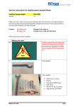
Service instruction for displacement pumps Mixon Valid for pump model: 521-1300 Version: 1.1 Before you start, make sure you have required tools, this instruction, the required spares and have answered your possible questions related to the service of this pumps with the technical staff of Mixon (+46 303 24 66 60) Purpose: A: Packing set: B: Repair set: Change of all o-rings, or Change of all o-rings and ball valves Follow these instructions carefully! Before you start 00 Switch of electricity of the electrical cabinet and release pressure of the glue system by opening the dosage test and switch off the compressed air! 0 Tools needed: 1 Tools needed: Model: 521-1300 Allen key 6, 8, 10mm Pincers Screwdriver NOT sharp Bolt 16mm Wrench 17, 18, 19, 22mm Large wrench 24-65mm Side 1 2 Close inlet valve to both glue- and hardener filter 3 Place bucket under the pumps/hoses to collect the glue hardener in the hose between filter and suction side of the pump, when the hoses are removed. Unscrew the locks of the oil reservoirs on top of the pumps and catch-up the oil (LP-802) from the reservoirs in a bucket. 4 Dismantling of pump 5 Unscrew the pressure hose, including the equalizer from the pump. The hose and the equalizer may stay connected. Release here. Model: 521-1300 Side 2 6 Release the screws of the fixation of the hose on the bottom side of the pumps and remove the hose(s). Collect glue and hardener inside the hose in a bucket. 7 Release the screws of the connection slave pump on the leveler arms. 8 Remove the connection piece. 9 Remove the bolts from the top of the hydraulic motor to the leveler arms. Model: 521-1300 Side 3 10 Release the arms from the hydraulic motor. 11 Place the axel of the hydraulic motor in highest position (move up). This allows that the top of the piston of the pump can be reached from the opening of the pump distance, see picture 12. 12 Here you can place the wrench to release the pump axel from the axel of the hydraulic motor. Model: 521-1300 Side 4 13 Unscrew the piston of the pump from the hydraulic motor. Hold the wrench on the top of the pump (inspection hole oil) in a fixed position and release the axel of the hydraulic motor (move counter clockwise) with the other wrench. 14 Unscrew the 3 bolds on the underside of the pump. 15 Unscrew and release the three bolts. 16 Pump is now ready to be removed. Model: 521-1300 Side 5 Remove all wearing parts 17 Take of the pump from the pumpdistance. The washer and O-ring will fall off. 18 Draw the piston out of the cylinder by the power of or hands. Draw in line of the cylinder. 19 Carefully draw the piston out of the cylinder of the pump. This area of the piston may under no circumstances be damaged!! 20 Model: 521-1300 Clean the piston, the cylinder and parts which are in contact-contaminated with glue/ hardener. Use preferably warm water and brush. Most important to follow the recommendations/instructions of the adhesive supplier how to clear their parts in contact with the adhesive. Do not use under any circumstances sharp metal objects to clean or remove (hardened) adhesive. Side 6 21 Remove the bottom part of the cylinder of the pump. Use large wrench. Remove part clockwise. 22 Un-screwed bottom ball valve house. 23 Remove the ball stop. 24 Take the bottom valve apart. Remove the ball. Clean the housing with warm water. Model: 521-1300 Side 7 25 Now we focus on the piston of the pump. Start to remove the lower part, the piston hub. 26 Remove the piston hub and washer on top of the hub. 28 We remove all the tightening case from the piston. 30 Remove all the O-rings/scraper and clean the piston hub after parts are taken off. Model: 521-1300 Side 8 All the parts removed from the hub. 31 Now remove the O-rings from the tightening case. 32 Dismantled tightening case. Model: 521-1300 Side 9 33 Pump is now fully dismantled. Assure all is 100% clean before you start renovating the pump with new wearing parts. Repair set 34 Packing set Art. Nr.: 521-1390 All new O-rings and scrapers 35 Repair set Art. Nr.: 521-1395 All new O-rings , scrapers and balls. 36 37 Model: 521-1300 When put the pump together make sure all the parts are put on a clean working area. Never use violence the put the parts together. Never use sharp objects to place parts/ O-rings in place. Always use the appropriate tools to put parts together. In case of any serious doubt, please contact Mixon for professional assistance. Take All the components from the repair set out of the plastic bag and check before you start if all the parts are complete in the set. (Compare with parts you have removed). If set not complete contact Mixon. Side 10 Renovation, put new parts in place 38 We start with the renovation of the pack-box. 39 Place the green O-ring over the housing of the pack-box. 40 Place the gasket in the pack- box. Model: 521-1300 Side 11 41 Place the metal washer on top of the gasket. 42 Place the black O-ring over the white scraper and place this in the pack-box. 43 Place the green O-ring over the outside of the pack-box in the opening. 44 Place the last metal washer on the top of the pack-box. The pack-box is now renovated, Model: 521-1300 Side 12 45 Now we renovate the piston hub, all required parts 46 Start to place the support ring on the piston. 47 Place the sealing on the hub, the “open-end” towards the pressure part of the pump! 48 Place the gasket. Model: 521-1300 Side 13 49 Place the packing on the hub. 50 Like this Place the hub back on the piston, insert the ball and screw the valve seat on its place. 51 Model: 521-1300 Mounted on the piston. Side 14 52 Place the pack-box on the other side of the piston. 53 Place first the metal washer and then the pack-box on the piston. Use little grease before mounting 54 The piston is now renovated. 55 Place the piston in the cylinder, to make this moment more easy use a bit of LP-802 on the points of contact between piston and cylinder. 1 Make sure piston and cylinder are in line, do not use any other tools than your hands!. Packing box comes easy in place if you use the washer to push the box in the cylinder Model: 521-1300 Side 15 56 Piston is now again placed in the cylinder. 57 Now we need to place the new ball in the bottom valve of the pump. 58 Place the ball stop in position after the ball is placed in the housing. 59 Mount ball valve in the cylinder, turn clock-wise Model: 521-1300 Side 16 60 ¨Pump is now renovated and ready to be build-in the dosage unit. 61 Now use the three bolds 62 Follow steps 2 to 17 in reversed order (start at 17 and work back to point 2. Top view of part picture 64 can be seen on picture 65. 63 Model: 521-1300 Side 17 64 Important while connecting the axel of the hydraulic motor on the lever arms!! Make sure the connection is in line! 65 Close the plug of the reservoir and fill up with oil LP-802 66 Oil LP-802, purchased from Mixon 67 Check after all is installed again correctly if there are no leaks on the pressure- or suction side. Dense if required. 68 Done Model: 521-1300 Side 18 Spare parts for 521-1300 pump: 521-1390 521-1395 packing set repair set Company details Mixon AB Traktorgatan 5 SE-442 40 Kungälv Sweden Tel: +46 303 24 66 60 Fax: +46 303 942 55 Web: Mail: www.mixon.se [email protected] Model: 521-1300 Side 19 Pump 521-1300 Model: 521-1300 Side 20 Pump 521-1300 Ref nr / Ref.No. 1 2** 3* 4* 5 6* * 7 8 9 10 12 13** 14** 15 16 17* 18 19 20* 21 22** 23 24 25* 26* 27* 28** * **+* Detaljnr / Part No. 521-1205 521-1310 111-6244 116-7140 521-1315 113-7134 111-6309 521-1320 521-1025 151-0308 140-0816 521-1335 521-1330 521-1065 123-1270 521-1070 321-1028 133-0530 A4 151-0305 111-6396 521-1005 521-0010 111-6118 520-1240 123-0472 520-1340 520-1345 115-7190 520-1355 114-1131 520-1275 666-9600/12 521-1390 521-1395 521-1300 521-1302 Model: 521-1300 Antal / Quantity 1 1 2 1 1 1 1 1 1 2 2 1 1 1 1 1 1 1 1 1 1 1 1 1 1 1 1 1 1 1 1 1 Benämning Bricka Tätningshus O-ring Tätning Bricka Tätning O-ring Bricka Bygel Mutter Bricka Kolvstång Cylinder Kulstopp Kula Ventilsäte Anslutningsmuff Skruv Mutter O-ring Fläns Uttagshus O-ring Kulstopp Kula Bricka Kolv Tätning Lager Packning Ventilsäte Säkerhetsventil Packningssats Renoveringssats Pump, kompl, inkl uttagshus o säkerhetsventil Pump, kompl, exkl uttagshus o säkerhetsventil Description Washer Tightening casing O-ring Gasket Washer Gasket O-ring Washer Clamp Nut Washer Piston rod Cylinder Ball stop Ball Valve seat Connection sleeve Screw Nut O-ring Flange Output casing O-ring Ball stop Ball Washer Piston Gasket Bearing Packing Valve seat Safety valve Packing set Repair set Pump, compl, incl., terminal housing and safety valve Pump, compl, excl., terminal housing and safety valve Bezeichnung Scheibe Dichtungsgehäuse O-Ring Dichtung Scheibe Dichtung O-Ring Scheibe Bügel Mutter Scheibe Kolbenstange Zylinder Kugelanschlag Kugel Ventilsitz Anschlussmuffe Schraube Mutter O-Ring Flansche Entnahmegehäuse O-Ring Kugelanschlag Kugel Scheibe Kolben Dichtung Lager Packung Ventilsitz Sicherheitsventil Packungssatz Reparatursatz Pumpe, kompl., einschl. Entnahmegehäuse u. Sicherheitsventil Pumpe, kompl., ausschl. Entnahmegehäuse u. Sicherheitsventil Side 21