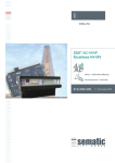
1
ANNEXURE TO TENDER NO. DPS/MRPU/NRPP/ENG/4653/TPT-1101
Description of item: Design, Manufacture, Assembly, Inspection, Shop testing,
Supply and Installation of Stainless Steel Blowers (4 Nos) at TRP, Tarapur with base
frame, vibration isolating pads, gas inlet/outlet flexible bellows, counter flanges with
fasteners, flexible/resilient coupling, electrical motors and VFD for largest capacity
motor including removal of existing blowers, motors and VFDs.
Note: Tenderers who are willing to respond for the subject tender, may contact with full
details ( address with phone, fax and email ) on email id - [email protected],
[email protected], [email protected] so as to get details of prebid meeting
before submission of technical and price bids.
Technical Specification of Stainless Steel Off-gas Blowers
1. Scope:
The scope of work includes design, manufacture, assembly, inspection, shop testing, supply
and installation of stainless steel blowers, as detailed below, with base frame, foundation,
vibration isolating pads of polybond / Dunlop make, gas inlet/outlet flexible bellows, SS 304L
counter flanges with gasket & fasteners, flexible/resilient coupling, electrical motors and VFD
for largest capacity motor. Removal of existing blowers, motors and VFDs is also in the scope
of the vendor.
1.1 Performance details with quantity:
Sl.
No.
Blower Description
Blower type
1
2
Capacity (CMH)
Static Pressure (mm WC)
Type-I
1000
1725
Type-II
2000
2150
3
Quantity (nos)
2
2
2. Applicable Standards & Codes:
Latest edition of the following codes and standards shall be applicable. In the event of any
conflict between any requirement in this specification and that of the applicable codes and
standards, the governing requirement shall be the more stringent of the two at the discretion of
the purchaser.
API 673
: Centrifugal Fans for Chemical, petroleum & Industrial services
IS: 4894 / DIN 24163
: Specification for centrifugal fans.
ISO 2372 / VDI 2056
: Vibration severity & group classification.
ISO 1940 / VDI 2060
: Balancing quality requirements.
ASME Sec. V
: NDT requirements.
ASME Sec. IX
: Welding Qualifications.
3. General Design Requirements as per standard API 673:
3.1. The blower shall be of centrifugal type having radial blade design. The blower shall be
SISW, Arrangement-1.
3.2
The equipment (including auxiliaries) shall be designed and constructed for a minimum
service life of 20 years and at least 3 years of uninterrupted service.
3.3 The vendor shall assume unit responsibility for all auxiliary systems included in the scope of
order.
3.4 Many factors such as ducting loads, alignment at operating condition, place of installation
effect of other running blowers in nearby at site may adversely affect the performance of
blowers. To minimize the influence of these factors, the vendor shall visit the purchaser’s
site and review the site conditions and assess the external forces and moments, weather &
Page 1 of 16
environmental conditions and shall ensure that these effects will not affect the performance
of blower.
3.5. The design shall be such as to select blower for optimum static & mechanical efficiency
The blower shall have stable operation in the range of 20% to 110% of the rated
capacity.
3.6. Blowers shall preferably be of single stage design. In case more then one impeller is
needed to achieve desire static proper justification for its selection shall be provided.
3.7. Operating speed of the blowers shall be less than 2500 rpm. The critical speed of the
blower shall be at least 1.5 times the operating speed. The operating speed range shall be
20% to 105% of maximum speed. The vendor shall determine that the drive train critical
speeds will not excite any critical speed of machinery being supplied. The entire drive train
shall be suitable for operation in the specified operating speed range. A list of all
undesirable speeds from zero to trip shall be submitted to the purchaser for review.
3.8. The blower shall be suitable for exhaust air at 50 deg.C and containing low
concentration of nitrous corrosive fumes.
3.9 The discharge and inlet of the blowers shall be circular. In case if it is rectangular
transition piece shall be provided. It shall have suitably drilled flanges for ease of flexible
bellow connections and it shall be rounded off to next higher nominal sizes of standard
pipes and flanges meeting the standards.
3.10. Base plate & mounting plates shall be provided as per the standard. API 673.
4. General Construction Details:
4.1 Material Of Construction: The material of construction is as specified below for different
parts of the blowers . Material test certificates (physical & chemical check) of the parts shall be
submitted to the purchaser for its review. All components with weld / upon which welding has to
be carried out during fabrication shall have corrosion rate ≤ 18 mpy when tested as per ASTM A
262 IGC Pr. ’C’. Check Tests for material conformation shall be carried out in presence of
purchaser's inspector.
Impellers
: AISI SS 304L/316L as per ASTM
A240
Casing
: AISI SS 304L/316L as per ASTM
A240
Casing Stiffeners/Bracing
: AISI SS 304L/316L as per ASTM
A240
Shaft
: AISI SS 304L/316L as per ASTM
A276
Flexible bellow
: Stainless steel
Base frame
: Structural Steel as per IS 2062
Shaft seal
: Mechanical seal
Bearing & bearing housing
: Standard Original SKF
Hardware (nuts, blots, washers):
Stainless Steel
4.2 Component Specific Requirements:
4.2.1 Blower Casing: The housing shall be fabricated from plates of minimum 6.4 mm
thick, accurately cut & formed and continuously welded throughout for added strength and
total air tight construction. The casing shall be suitably stiffened by means of angles/flats as
required. The casing shall be radial split type. The cut off shall be so designed to give
smooth quiet & efficient performance of air from blower outlet. All bolts /studs welded to the
casing for end cover or stiffening angles support shall be welded from out side with pad
plate. Inside surface of casing shall be smooth without any projections of bolt heads etc.
The casing weldments shall be D.P. tested for root and final passes. If necessary, provision
for ready access to interiors of casings and other possible trouble points shall be made by
means of readily removable, bolted on plates or hinged and latched doors. Inlet and
Page 2 of 16
discharge connections shall be flanged and bolted. ASME B 16.5 or 16.47 standard flanges
shall be provided. Casing shall have drain point at bottom.
4.2.2 Mounting: The fan & motor should be mounted on a common base. An inertia mass
may be provided to restrict the amplitude of vibration. Center of gravity must be below the
top of the mass. Wide flange steel beams with depth equal to greater than the 1/10 of
longest span of equipment. Vibration Isolators shall be so arranged that load is distributed
equally to all isolators to achieve equal static deflection. Isolation efficiency shall be
minimum 92%. Isolator transmissibility ratio shall be less than 0.01. No global frame
resonance is allowable within design operating frequency range. Make of the vibration
isolator shall be Dunlop or Polybond.
4.2.3 Impellers: Impeller blade design shall be radial type solid blades of minimum 6mm
thick. Impellers shall be both statically & dynamically balanced. Balancing shall be carried
out with impellers mounted on its own shaft while maintaining the actual assembly
conditions. The balancing grade shall be Gr.2.5 as per ISO 1940/ VDI 2060 and the vibration level
shall be as per ISO 2372/VDI 2056. Wheel radial & axial run out shall not be greater than
0.003 X OD. Welded counterweights shall not be thicker than base material, full radius
corners, continuous weld, min one inch distance from wheel outer periphery. All welding of
weights to be completed prior to balancing. A copy of balancing report showing balance
machine calibration & date, initial unbalance, final unbalance, residual unbalance check,
weight correction and location shall be submitted to the purchaser. The impeller shall be
positively locked to the shaft to prevent it from getting loosened. Locking device shall be
amply designed for full force of sudden start and stop. Impeller blades shall be die formed.
Shrouds, back plate shall normally be of one-piece construction. Blades shall be fully welded to
back plate on one side and on other side it will be partially welded and partially plug welded to
the shroud. However preference will be given to the best design. Blades shall be designed
and constructed to prevent internal accumulation of condensable foulants or corrosion
products. The class of construction shall be one or higher grade. The minimum thickness of
the components shall be 3mm. Model testing and FEA shall be carried out to determine fan
resonance, structural resonance, critical speed etc.
4.2.4 Shaft: Shaft of the blower shall be amply designed to take up the various torque and
bending moments of the total system. It should be well designed with fillets & radii to take
discontinuous stress at various section changes. The shaft shall be finished to close
tolerances at impeller, seal, bearing and pulley diameters. The size of shaft shall be
calculated on the basis of combined shear stress. This shear stress shall not exceed 30
percent of elastic limit in tension or 18 percent of ultimate tensile strength. The shaft shall be
UT tested as per ASTM A-503, 609. Raw material test for checking chemical properties for
shaft material shall be carried out. Shafts shall be of one piece, hot rolled steel, heat treated
after machining. The shaft shall be stress relieved after rough machining.
4.2.5 Bearings: The bearing of the shaft shall be of anti friction type of original SKF make.
Independent plumber blocks for housing two bearings shall be provided. Bearings selected
shall be designed for the life of at least 1,00,000 hours and capable to take necessary radial
load and net axial thrust. Bearing housing shall be of original SKF make and rest on
machined surface and properly located by dowels. The bearing support plate shall not exhibit
structural resonance within the operating speed range of fan. Minimum thickness of bearing
support plate shall be 1 inch and shall be machined to obtain 0.002 to 0.003 inch/foot
flatness. Anti friction bearings shall be grease lubricated. The vendor shall perform a thermal
analysis of the bearings taking into account the heat conducted by the shaft and maximum
specified ambient temperature. The lubrication method will be reviewed and approved by the
purchaser. The vendor shall provide in the service manual a lubricant specification, a
recommended re-lubrication interval and a recommended clean and repack interval for the
specific application. Bearing housing shall have a threaded connection for permanently
mounting vibration transducers in accordance to API 670.
Page 3 of 16
4.2.6 Shaft Seal: Out side mounted unbalanced multi spring mechanical seal shall be offered
for all the blowers The seal material shall be compatible for the service fluid, i.e., air with
acidic fumes. The seal shall be of reputed make proven design and shall be approved by the
purchaser. Material for mating surfaces SiC, hardware stainless steel and secondary seals
PTFE.
4.2.7. Power transmission: V-belt drive suitable to transmit the required power shall be
provided to all blowers. All belts shall be oil resistant and shall be of static-conducting type.
The service factor shall not be less than 1.75 times the driver name plate power rating. The
V-belt drive shall be suitable for the operating speed specified and shall facilitate ease of
assembly & maintenance. The vendor shall provide a positive belt tensioning device on all
drives. This device shall incorporate a lateral adjustable base with guides and hold down
bolts, two belt tensioning screws and locking bolts. To reduce bearing moment loading the
sheave overhang distance from sheave to shaft bearing shall be minimized. Sheave runout
shall be less than 0.002 inch radial and axial direction. Sheaves shall meet the balance
requirements of ISO 1940/VDI 2060, Grade 6.3. Pulley shall be FENNER make Taper lock
bushing.
4.2.8. Flexible Bellows: All blowers shall be supplied with a pair of stainless steel bellow;
suitable for inlet and outlet connections with counter flanges, nuts and bolts. Supporting
design calculations and selection for number of convolutions and thickness shall be furnished
to the purchaser. All blowers shall be supplied with bellows face welded to flanges.
4.2.9 Lifting Provision: Suitable lifting lugs shall be provided with each type of blower for
handling during installation and maintenance as well.
4.2.10 Drive Motors: The prime movers for blowers shall be of squirrel cage type induction
motors with rating as per Table IV of API standard 673. (Refer Annexure-III).
4.2.11 Spare Parts: The supplier shall quote separately for spare parts of blower for trouble
free service for at least five years. However, it will be at the purchaser's discretion whether to
buy it or not.
4.3. Fabrication:
4.3.1 The work shall be carried out in clean and dust free environment so as to avoid
contamination of stainless steel components.
4.3.2 To achieve the highest reliability of blower manufacturing, latest techniques such as
laser cutting for cutting of impeller shroud plates, low heat welding techniques for welding of
blades to the back plate and shroud etc. shall be employed. The supplier shall specifically
mention the machineries available with them to carryout this work.
4.3.3 All welding, including repairs, shall be performed by welders, and procedures qualified in
accordance with the specification of AWS D1.1 for housings and structural components and
AWS D14.6 for rotating components. The weldments on impeller and casing shall be
subjected to D.P. test for the first and final pass. All butt welds on rotating elements shall be
continuous full strength and full penetration welds.
5. General Inspection & Testing Requirements:
All details of the characteristic curves, calculations & technical details shall be furnished for
the above. The blower shall be tested in all cases prior to performance test by the supplier
and shall furnish the details of the test to the purchaser for approval of carrying out of
performance test.
6.
Inspection & Testing at Manufacturer's Works:
6.1 Inspection: The blowers shall be subjected to inspection to cover dimensional accuracy,
Page 4 of 16
material used, workmanship, make and quality of bought out items. The supplier shall
furnish material test certificates (physical, chemical & IGC) for purchaser's review.
Cross-examination will be carried out by the purchase and if necessary involvement of
third party will be arranged by the supplier and charges will be under their scope. The
supplier shall also furnish all the relevant test certificates on bought out items. A
detailed QAP and time related chart indicating different stages of work shall be
submitted to the purchaser for approval. Supplier shall inform well in advance the
different stage of the work progress for stage inspection as per the approved QAP.
6.2
Run Test: This test shall be carried out on each unit at manufacturer's work to
examine vibration & noise after assembly.
6.2.1 Prior to rotor assembly the shaft shall be inspected for mechanical run out and
concentricity at impeller mounting surface and bearing journal. Total indicator reading
shall not exceed 50/25 microns as per 2.7.4.1 of API standard 673.
6.2.2 After the final balancing of each assembled rotating element has been completed,
residual unbalance check shall be performed and recorded and residual unbalance
shall not exceed the values for balance grade G2.5.
6.2.3. Each blower unit shall be run at various speeds. The amplitude & frequency of
vibration shall be measured at various locations on the blowers. The maximum
allowable unfiltered peak amplitude of vibration in any plane shall not exceed the
limits specified in table 2 of API standard 673.
6.2.4 Background level of noise (Db) & noise level with blower in operation shall be
recorded to determine the noise level of the blower. Maximum noise level shall not
exceed 80 dB.
6.2.5 Each blower shall be run continuously for six hours or till the bearing temperature
stabilizes. During this the bearing temperatures, motor current, supply voltage etc.
shall be monitored.
6.2.6 Performance tests of all the blowers will be carried out at suppliers works as per
AMCA 210.
7.
Performance Guarantee:
Supplier shall give performance guarantee for the blowers running under the specified
condition and shall replace any part in the event of failure due to design and
manufacturing faults for a minimum period of one year from the date of installation.
8. Documents, Drawings & Data to be Furnished with Offer:
Supplier shall submit catalogues, drawings and the followings along with the offer
• Blower datasheet: (as per annexure-I).
• Price schedule & Schedule of recommended spares (as per annexure-II).
• General arrangement drawing with major dimensions.
• Part list with codes and material of construction.
• Performance curve with duty point marked.
• Selection charts or curves.
• List of similar orders executed for various DAE units with its reference.
• Quality assurance programme.
9. Documents to be Submitted after Award of Contract;
After receipt of purchase order, the supplier shall submit to the purchaser for his approval
4 copies of the certified dimensional drawings of the blower motor assembly,
characteristics curves for blowers and motors considering minimum and maximum
ambient temp, minimum and maximum humidity, minimum and maximum frequency,
materials of construction, make, type specification of motor bearings, Flexible coupling,
shaft seal etc. and design information to support the correctness of selection on bearing,
shaft critical speed. Detailed to scale dimensioned general arrangement drawing of
blower and motor giving foundation details, loading data like static and dynamic loads,
unbalanced forces and moments if any, pocket details..etc. Overall space and headroom
requirement with details of handling during erection, operation and maintenance of the
equipment. The fabrication and use of the parts shall start only on receipt of purchaser's
Page 5 of 16
approval on these. Also the supplier shall furnish a detailed schedule of manufacture &
delivery.
10. Final Documentation;
The supplier shall furnish 5 copies of inspection documents along with instruction
manuals
Five copies of documents pertaining to inspection and testing containing material test
reports stage inspection reports, radiographic report, if any, performance report,
balancing report, , motor test report, VFD drive test report etc shall be submitted along
with delivery of the blowers. Soft copy of drawings and manual shall also be submitted in
CDs. The supplier shall furnish 5 copies of instruction manuals to cover installation,
operation, and maintenance, drawings for each type of blower. The manual shall include
instructions on alignment; lubrication details specifications of parts etc. The purchaser
shall approve the manual before full supply is made.
11. Cleaning, Protection and Painting:
All equipments shall be neatly finished in workmanship like manner. All exposed metal
surfaces shall be smooth and free from burrs. Finished surfaces shall be protected
against corrosion and mechanical damage.
12. Packaging & Shipment:
The blowers shall be shipped to PREFRE stores, NRB, BARC Complex, Tarapur. P.O.
Ghivali. Dist.- Thane. Maharashtra- 401502, only after obtaining a shipping release from the
purchaser or his authorized representative. The supplier shall be fully responsible for
protective measures to ensure the safe delivery of blower's by this specification to the site.
All the parts shall be packed properly boxed and protected to prevent all possible damage
during transportation. The supplier shall consult the representative of the purchaser to
satisfy himself that adequate measures have taken.
13. Installation & commissioning:
Installation and commissioning will be under the scope of the supplier. It includes design,
detailing and erection of foundation, isolation from external effects, installation of
equipment and connection with existing pipeline. After installation, performance check of
the machine and its drivers will be carried out for meeting the specified acceptance
criteria. The performance will be observed for atleast three months and its parameters
should be within acceptable limits.
14.
Drawings:
All the drawing shall be made on computers using latest version of Auto Cad software
and shall be submitted along with delivery.
15.
Vendor Evaluation Criteria:
The following information is to be submitted along with the offer for evaluating the
vendor
1.
Annual turnover of the company
2.
Similar orders executed preferably within DAE unit.
3.
Performance report submitted by the user for the executed orders.
4.
A separated dedicated facility for SS machining and fabrication like storage,
workshop, tools, equipments etc.
5.
CNC machines to carry out precision machining of components
6.
Advanced low heat welding equipments for welding of SS components.
7.
Test rigs for conducting blower performance test as per AMCA requirements.
8.
Latest instruments to measure the critical parameters like surface finish,
linearity, alignment, balancing, vibration, noise etc.
Page 6 of 16
16.
General:
1.
2.
3.
17.
The installation work will be in radioactive area.
First order for one blower will be given and its performance will be observed at
site after installation for period of three month. The order for the remaining
blowers will be given after satisfactory performance of the first blower.
Supplier shall quote spares for five years of trouble free operation.
Essential Criteria for vendor for qualifying in Part I:
The vendor (OEM/authorized dealer) shall have to show already supplied and
installed by them the blower of similar type and capacity which has vibration and noise level
less than or equal to the limits mentioned in the technical specifications and offer shall
contain performance certificate from user. Failing to do so will result into outright rejection
of offer.
Since the item is being procured for critical application, after sales services support
from the OEM is most important requirement for us. In view of this offers from OEM or
authorized dealers/preferred channel partners of OEM only will be considered. In case
OEM is unable to quote directly, a letter marked to the department, confirming the
competence and experience of the bidder in handling, supply & after sales services support
from the OEM must be submitted. This is to ensure proper and timely supply of the material
and uninterrupted after sales service support. Offers without OEM authorization letter as
said above will be outright rejected.
Page 7 of 16
Annexure I
Specific Requirements of Blower
1. Blower Characteristics
:
Centrifugal
type,
Radial
blade
with SISW,
Arrangement-1, preferably single stage
2. Operating Fluid
:
Gas containing nitric acid fumes
3. Operating Fluid temperature
:
50 Deg. C
4. Duty
:
Continuous, Heavy duty
5. Operating speed (rpm)
:
Below 2500 rpm
6. Range of Operation
:
20 - 110 % of rated Capacity
7. Shaft seal
:
Mechanical seal
8. Shaft Bearing
:
Original SKF make
9. Impeller balancing
:
As per VDI2060/ G-2.5 conforming to ISO1940/1
10. Vibration level (RMS Velocity)
:
As per VDI 2056 (Less than 3.0 mm/sec)
11 . Noise Level
:
Below 80 dBA
12. Bearing Temperature
:
Ambient + 40 Deg.C (max.)
13. Bellows
:
Spring rate 4 Kg/mm
Performance details with quantity
Sr.
Description
1
2
Capacity (CMH)
Static Pressure mm WC
Blower type
Type-I
1000
1725
3
Quantity (nos)
2
Type-II
2000
2150
2
Page 8 of 16
Annexure II
Blower Datasheet
(To be furnished by bidder along with the offer)
1.
Manufacturer and model no. :
2.
Type :
3.
Numbers
:
4.
Blower rated speed (rpm)
:
5.
Performance:
(i) At air standard density at 760mm of Mercury
and 20 deg. C temperature and at rated speed :
(ii) At operating temperature (50 Deg.C)
:
6. Outlet velocity (m/min)
:
7. Critical speed (rpm)
:
8. Air B.H.P.:
(i). B.H.P. required at rated speed (at 50 Deg.C)
:
(ii).B.H.P. required at rated speed (at 20 deg. C)
:
9. Limit load BHP
:
10. Static efficiency (percentage)
:
11. Details:
(i). Wheel diameter (mm.)
:
(ii) Blower tip speed (m/s)
:
(iii) Blower outlet area. (m2)
:
(iv) Temp rise (deg C)
:
12. Overall wheel width (mm.)
:
13. Materials and their thickness:
Sr. No. Item
Material
Thickness/Dia Sr. No. Item
Material
meter (mm)
i
Casing
iv
Impeller
ii
Back plate
v
Gaskets
iii
Shroud
vi
Shaft
14. Blower Bearing
(i) Type
(ii) Size
(iii)Life
Thickness/Dia
meter (mm)
15. Blower drive:
(i) Type of blower drive
(ii) Drive losses in HP and % of motor BHP
16. GD2 value (kg.m2) of impeller
17. Vibration isolator:
(i). Manufacturer (ii). Size (iii).Numbers
18. Flexible Bellow:
(i). Type
(ii). Size
(iii). Bellow thickness
(iv). No. of convolutions
(v). Vibration attenuation factor
19. Noise level (in decibels)
20. Vibration (RMS Velocity)
21. Shaft Seal:
(i). Make (ii). Type
22. List of spares
Page 9 of 16
Annexure III
Specification of Squirrel Cage Induction Motors
1. Scope:
This specification covers technical requirements for the design, manufacture, inspection
testing, packing for shipment and supply of energy efficient squirrel cage induction motors
required as prime movers for and as an integral part of centrifugal type off gas blowers as
specified in this document.
2. Applicable Standards:
Latest version of the following standards shall be used.
IS-12615
:Energy efficient 3 phase squirrel cage induction motor.
IS -325
: Specifications for 3 phase Induction Motors.
IS-1231
:Dimensions of 3 phase foot mounted induction motor.
IS-1271
:Thermal evaluation and classification of electrical insulation.
IS- 2253
:Designation for types of construction and mounting arrangement of rotating
electrical machines.
IS - 3202
:Code of Practice for climate proofing of electrical equipment.
IS-4029
:Guide of testing 3 phase induction motors.
IS-4691
:Degrees of protection provided by the enclosure for rotating electrical machinery.
IS-4722
:Rotating Electrical machines.
IS -4728
:Terminal marking and direction of rotation of rotating electrical machinery.
IS-4800
:Enameled copper winding wires.
IS - 12075
:Specifications for limits of vibration of the motors.
IS - 12802
:Temperature Rise Measurement of rotating Electrical machines
IS 12824
: CBIP Recommendation of Motors.
3. Technical Specifications
i.
Make
: M/s Bharat Bijlee, M/s ABB, M/s Siemens
ii.
Type of enclosure
: T.E.F.C., IP 55 as per IS - 4691
& degree of protection
iii)
Type of Duty
: Continuous
iv) No. of phases
: 3 phase
v)
Rated Voltage
: 415 V+/- 10%
vi) Frequency
: 50 Hz.+/- 5%
vii) Class of Insulation
: F , Temperature rise limited to class B
viii) Speed of Revolution
: Shall be compatible with Blower
ix) Earthing
: Two nos. of earthing terminals of proper size shall be provided.
x) Rotor
: Squirrel Cage
xi) Control of Speed
: Variable Voltage Variable Frequency Drive
xii) F.L. Starting current
: Not exceeding 600 % of FL current (DOL Starter)
xiii) Winding
: Copper wound, Inverter Grade/VFD Compatible
xiv) Fault Capacity of System to which motor is to be connected: 35 MVA
xv) Motor is driven by VWF drive which will introduce harmonics. Motor should be designed to
withstand temperature rise due to harmonics. Motor winding shall have nos. of
Thermal switches of proven performances to trip motor in case temperature exceeds
preset limit.
xvi) Rating of motors shall be suitable to the Blowers.
xvii) Terminal Box shall be of adequate size to accommodate cable one size higher than the
minimum recommended. There shall be provision to change orientation of cable box to
suit condition for entry of cable.
Page 10 of 16
4. Drawings: Drawings showing general arrangements, frame, foundation, weight etc shall be
submitted along with the technical specifications of the bid. Approved drawings shall be obtained
from the purchaser prior to the fabrication.
5. Inspection & Testing:
i. The supplier shall perform acceptance & routine tests for all the motors and type test for
one motor as per latest version of IS - 325 & IS - 4029 at the motor manufacturer' works.
The test reports shall be submitted to the Purchaser for its review before dispatch.
ii. The supplier shall notify the purchaser the date and location for the tests giving sufficient time
for the purchaser or his authorized representative to be present. The test procedure shall be
approved by the purchaser.
6. Packaging;
All motors shall be properly packed to protect for the entire period of dispatch, storage and
erection, against corrosion, incidental damage, due to vermin, sun light, rain, high
temperature, humid atmosphere, rough handling in transit and storage hi open including delays
in transit.
7. Spares: Prices of recommended Spares for 3 years trouble free operation shall be
mentioned in the bid.
Page 11 of 16
Annexure-IV
1. Make :
Datasheet of LT Squirrel Cage Induction Motors for Blower
(To Be Furnished along with offer)
.
2. Applicable Standard
3. Type of enclosure & degree of protection
4. Type of Duty
5. No. of Phases
6. Voltage & Frequency (with variation)
7. Class of Insulation
8. Frame Size
9. Rating in KW
10. Speed of Revolution
11. Direction of Rotation
12. Earthing
13. Rotor
14. F.L. Starting current (% FL)
15. Fault Capacity of System to which motor is to be
connected
16. Torque Speed Characteristics
17. Thermal Withstand Capacity
18. Temp. Rise of Winding
19. Temp. Rise of Bearing
20. Degree of Protection
21. Fault Withstand capacity & Duration
22. Thermal Switch for Motor winding:
a) Make
b) Contact rating
c) Insulation Resistance
d) Temp. Setting
23. Type Test Certificates
24. Winding Connection:
a) Stator b) Rotor
:
25. Whether Suitable for being controlled by VWF with Total Harmonic Distortion upto 5 % in both
Voltage and Current :
26. Recommended Cable Size
27. Terminal Box Dimensions
:
:
Page 12 of 16
Annexure-V
Specification of Variable Voltage Variable Frequency Drives
1. Scope:
This specification covers the inspection & testing manufacturer's works and supply,
installation & commissioning of Variable Voltage Variable Frequency AC Drive (VVVF
Drives) required for speed control of 3 phase squirrel cage induction motors specified in this
document for largest capacity Centrifugal Blowers to maintain the upstream vacuum of the
system.
Sr. No.
Description
No. of drives
Type ‘II’
1
Quantities
2
2. Functional Requirements:
VVVF Drives selected should meet the following functional requirements:
The VVVF Drive shall be capable to operate the blowers up to 110% of blowers rate
capacity by increasing the speed of the blowers if need arises. It should also be able to
operate as low as 20% of the rated capacity of the blowers.
3. General Specifications of VVVF Drives:
(a) Variable Voltage Variable Frequency Drive (VVVF Drive) shall be air-cooled, static
speed controller using IGBT having total harmonic distortion not exceeding 5%.
(b) These Drives used for speed control of 3 phase squirrel cage induction motors coupled
with centrifugal Blowers used in Off Gas System in order to control upstream vacuum of the Off
Gas System by varying the frequency and voltage applied to the motor terminals.
(e) It shall have provision for digital indication for Measured Variable (MV), Set Point (S), and
Output.
(f) It shall have in built RFI filter and AC choke for harmonics suppression.
(g) It shall have both lockable local & remote operation facility.
(h) Drive shall have alphanumeric control panel with LCD indications of all essential
parameters like output frequency, voltage, current etc.
(i) Presently Siemens Make VVVF Drives of Type Micromaster 430 Rating 18.5kW,
38A, Code: 6SE430-2UD31-8DA0 are being used for driving 15kW Motor. The panel
make is Siemens. The supplied VVVF Drives should be compatible with existing
panel and its rating should be higher enough to drive the supplied motor and fan.
The supplied VVVFD shall be fitted in the existing panel without doing any major
modifications. The supply of input filter choke along with VVVF Drive is in the scope
of the supplier.
Page 13 of 16
4. Technical Specifications of VVVFD:
Specification
Input Voltage
Power
Technical Data
380 to 480V 10% 3AC
To Suit the Motor and Fan
Input Frequency
47 Hz to 63 Hz
Output Frequency
0 Hz to 650 Hz
Power Factor
Invertor efficiency
Overload Capability
Inrush current
≥0.95
96% to 97%
Overload current 1.4 x rated output current (i.e. 140% overload
capability) for 3s and 1.1 x rated output current (i.e. 110%
overload capability) for 60s, cycle time 300s
Less than rated input current
Control method
Linear V/f characteristics; quadratic V/f characteristics; multi
point characteristic (programmable V/f characteristics); flux
current control (FCC), energy saving mode.
Pulse frequency
4kHz (standard), 2kHz to 16kHz (in 2kHz steps )
Fixed Frequency
15, programmable
Skip Frequency bands
4, programmable
Set point resolution
0.01 Hz digital
0.01 Hz serial
10 bit analog
Digital Inputs
6 fully programmable isolated digital inputs; switchable
PNP/NPN
Analog Inputs
2 Programmable Analog inputs –
iii.
0 V to 10V, 0mA to 20mA and –10V to +10V
(AIN1)
iv.
0V to 10V and 0 mA to 20mA (AIN2)
v. both can be used as 7th / 8th digital input.
Relay Outputs
3, configurable 30V DC / 5A (resistive), 250VAC / 2A (inductive
load)
Analog Outputs
2, Programmable (0/4 mA to 20 mA )
Serial interfaces
RS-485, optional RS-232
Motor cable length
Protection Level
7.5KW to 90KW: Without output choke: Max. 50m (shielded),
max. 100 m (unshielded)
IP 20
Temperature range
7.5KW to 90KW: – 10 0C to +40 0C (+14 0F to +104 0F)
Storage temperature
– 40 0C to +70 0C ( – 40 0F to +158 0F
Relative Humidity
Installation height
95% ( non-condensing.)
7.5KW to 90KW : upto 1000m above sea level without derating
Page 14 of 16
Protection
Features for
i. Under voltage,
ii. Over voltage,
iii.
Overload,
iv.
Earth faults,
v. Short circuits,
vi.
Stall prevention,
vii.
Locked motor,
viii.
Motor over-temperature,
ix.
Inverter over-temperature,
x. Parameter PIN protection
CE Marking
Conformity with Low Voltage Directive 73/23/EEC
Dimensions &
weights
Make
H x W x D (mm) max:. 520 x 275 x 245, Weight, approx. (kg) 17, Max:
20kg
The VVVFD should be any one of the Make: Eurotherm/ Schneider/
ABB/ Siemens (Preferred as Siemens Make VVVFD is already in use in
Siemens Make Panel. It will make supplied VVVFD to be fit in the old
panel without any major modifications)
5. Installation and commissioning of VVVFD:
The installation and commissioning of the VVVFD is in the scope of the supplier. The VVVFDs
will be installed in the existing panel in the place of existing Siemens make VVVFD without
any major modifications in the panel. The commissioning of the VVVFD shall be done by the
qualified personnel from the manufacturer or its authorized service centre.
6. Applicable Standards: IEC/IEEE Standard.
7 Inspection & Testing:
7.1 All tests necessary to assure conformity with technical specifications for VVVF Drive shall
be carried out.
7.2 The supplier shall perform Acceptance and Routine Tests for all VVVF Drives as per
relevant standards. These test reports shall be submitted to the Purchaser for its review
before dispatch of the drives.
7.3
The supplier shall notify the purchaser the date and location for the tests giving sufficient
time for the purchaser or his authorized representative to be present. The test procedure shall
be approved by the purchaser.
7.4 The supplier shall demonstrate to the purchaser the successful run of complete VFD-MotorBlower assembly to meet the requirements of this technical specification.
8 Packaging;
a) VVVF Drives shall be protected for ocean shipment, inland transport, carriage at the site
and out door storage transit at the site.
b) Supplier shall be responsible for any damage to the items during transit due to improper
and inadequate packing.
c) Only packages constructed out of suitable material and of dimensions proportional to the size
and wt. Of contents shall be used.
d) All items shall be protected for the entire period of dispatch, storage and ejection against
corrosion, incidental damage, due to vermin, sun light, rain , high temperature humid
atmosphere, rough handling in transit and storage in open including delays in transit.
9 Transport:
a) No material shall be dispatched without prior consent of the purchaser or hi
representative.
b) Supplier shall intimate in writing the probable date when the equipment shall be ready for
dispatch at least within 10 days for foreign supply and five days for domestic supply in
advance.
Page 15 of 16
10. It is not the intent to specify here the complete details of design and construction of the
VVVF Drives required for Off Gas Blowers. However, VVVF Drives shall conform to the
high standards of engineering, design and workmanship and be capable of performing in
continuous operation up to the seller's guarantee in a manner acceptable to the purchaser
who will interpret the meaning of drawings & specifications and shall have the power to
reject any work or material which in his judgment are not in full accordance with
specifications.
11. Spares: Prices of recommended Spares for 3 years trouble free operation shall be
mentioned in the bid.
Annexure-VI
Datasheet of Variable Voltage Variable Frequency Drive (VVVF)
(To Be Furnished along with offer)
1. Make
2. Applicable Standard
3. a) Control Method
b) Control accuracy
4. Rated I/P Voltage
5. Output Voltage & Current with harmonic contents at 25, 50, 75 and 100% load
6. Output frequency
7. Over Torque Capacity
8. Under Torque Capacity
9. Control Input's
10. Control Output's
11. Communication
12. Acceleration / Deceleration Tune
13. Motor Protection
14. Speed Controller Protection
15. Std. Functions
16. Degree of Protection
17. Ambient Conditions
18. Operating Position
19. Dimension
20. Weight
21. Control panel details
Note: After publishing the tender, if there is any change in specification, it will be published as
corrigendum in the MRPU portal.
Accessories, Breakup costs etc. if any, may be quoted online in the ‘Price Bid Alternate Offer’
form.
Page 16 of 16