1
SPLIT-TYPE, HEAT PUMP AIR CONDITIONERS
SERVICE MANUAL
Series PEAD
Model name
<Indoor unit>
PEAD-A24AA5
PEAD-A30AA5
PEAD-A36AA5
PEAD-A42AA5
INDOOR UNIT
2014
CONTENTS
1. SAFETY PRECAUTION
2. PART NAMES AND FUNCTIONS
3. SPECIFICATION
4. FAN PERFORMANCE AND CORRECTED AIR FLOW
5. SOUND PRESSURE LEVELS
6. OUTLINES & DIMENSIONS
7. WIRING DIAGRAM
8. REFRIGERANT SYSTEM DIAGRAM
9. HEATER CONTROL
10. TROUBLESHOOTING
11. DISASSEMBLY PROCEDUR E
2
3
4
6
11
15
17
18
19
22
35
1 SAFETY PRECAUTION
1-1. ALWAYS OBSERVE FOR SAFETY
Before obtaining access to terminal, all supply
circuits must be disconnected.
1-2. CAUTIONS RELATED TO NEW REFRIGERANT
Cautions for units utilising refrigerant R410A
Use new refrigerant pipes.
Do not use refrigerant other than R410A.
In case of using the existing pipes for R22, be careful with
the followings.
· For A36 and A42, be sure to perform replacement operation before test run.
· Change flare nut to the one provided with this product.
Use a newly flared pipe.
· Avoid using thin pipes.
If other refrigerant (R22 etc.) is used, chlorine in refrigerant can cause deterioration of refrigerant oil etc.
Use a vacuum pump with a reverse flow check
valve.
Vacuum pump oil may flow back into refrigerant cycle and
that can cause deterioration of refrigerant oil etc.
Make sure that the inside and outside of refrigerant piping is clean and it has no contamination
such as sulfur hazardous for use, oxides, dirt,
shaving particles, etc.
In addition, use pipes with specified thickness.
Use the following tools specifically designed for
use with R410A refrigerant.
The following tools are necessary to use R410A refrigerant.
Gauge manifold
Charge hose
Gas leak detector
Torque wrench
Contamination inside refrigerant piping can cause deterioration of refrigerant oil etc.
Tools for R410A
Flare tool
Size adjustment gauge
Vacuum pump adaptor
Electronic refrigerant
charging scale
Store the piping to be used indoors during
installation and both ends of the piping sealed
until just before brazing. (Leave elbow joints, etc.
in their packaging.)
Handle tools with care.
If dirt, dust or moisture enters into refrigerant cycle, that can
cause deterioration of refrigerant oil or malfunction of compressor.
If dirt, dust or moisture enters into refrigerant cycle, that can
cause deterioration of refrigerant oil or malfunction of compressor.
Use ester oil, ether oil or alkylbenzene oil (small
amount) as the refrigerant oil applied to flares
and flange connections.
Do not use a charging cylinder.
If a charging cylinder is used, the composition of refrigerant will change and the efficiency will be lowered.
If large amount of mineral oil enters, that can cause deterioration of refrigerant oil etc.
Ventilate the room if refrigerant leaks during
operation. If refrigerant comes into contact with
a flame, poisonous gases will be released.
Charge refrigerant from liquid phase of gas
cylinder.
If the refrigerant is charged from gas phase, composition
change may occur in refrigerant and the efficiency will be
lowered.
[1] Cautions for service
(1) Perform service after recovering the refrigerant left in unit completely.
(2) Do not release refrigerant in the air.
(3) After completing service, charge the cycle with specified amount of refrigerant.
(4) When performing service, install a filter drier simultaneously.
Be sure to use a filter drier for new refrigerant.
[2] Additional refrigerant charge
When charging directly from cylinder
· Check that cylinder for R410A on the market is syphon type.
· Charging should be performed with the cylinder of syphon stood vertically. (Refrigerant is charged from liquid phase.)
2
Unit
Gravimeter
[3] Service tools
Use the below service tools as exclusive tools for R410A refrigerant.
No.
1
Tool name
Specifications
Gauge manifold
· Only for R410A
· Use the existing fitting specifications. (UNF1/2)
· Use high-tension side pressure of 5.3MPa·G or over.
2
Charge hose
· Only for R410A
3
Electronic scale
4
Gas leak detector
· Use the detector for R134a, R407C or R410A.
5
Adaptor for reverse flow check
· Attach on vacuum pump.
6
Refrigerant charge base
7
Refrigerant cylinder
· Use pressure performance of 5.09MPa·G or over.
· Only for R410A
· Top of cylinder (Pink)
· Cylinder with syphon
8
Refrigerant recovery equipment
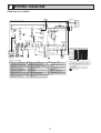
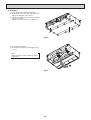
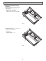
2 PART NAMES AND FUNCTIONS
• Indoor Unit
Air intake (sucks the
air inside the room
into the unit)
Air outlet
In case of rear inlet
In case of bottom inlet
3
3 SPECIFICATION
INDOOR UNIT
1 phase, 60Hz, 208/230V
15
2.63
Galvanized sheets
Plate fin coil
Sirocco fan × 2
0.121
2.10
14.5-18.0-21.0 (512-636-742)
35-50-70-100-150 (0.14-0.20-0.28-0.40-0.60)
Remote controller & built-in
30-32-36
30-33-37
30-34-38
31-36-39
33-38-42
32 (1-1/4)
1100 (43-5/16)
732 (28-7/8)
250 (9-7/8)
31 (69)
INDOOR UNIT
Service Ref.
Power supply (phase, cycle, voltage)
Max. Fuse Size
A
Min. Circuit Ampacity
A
External finish
Heat exchanger
Fan (drive) × No.
Fan
Fan motor output
kW
F.L.A
Fan motor
Airflow (Low-Mid-High)
m3/min (CFM)
External static pressure
Pa (in.WG)
Operation control & Thermostat
Sound pressure level
35Pa (0.14 in.WG)
(Low-Mid-High)
50Pa (0.20 in.WG)
dB (A)
70Pa (0.28 in.WG)
100Pa (0.40 in.WG)
150Pa (0.60in.WG)
Field drain pipe O.D
mm (in.)
Dimensions
W
mm (in.)
D
mm (in.)
H
mm (in.)
kg (lbs)
Weight
1 phase, 60Hz, 208/230V
15
2.73
Galvanized sheets
Plate fin coil
Sirocco fan × 2
0.121
2.18
17.5-21.0-25.0 (618-742-883)
35-50-70-100-150 (0.14-0.20-0.28-0.40-0.60)
Remote controller & built-in
30-33-38
30-34-39
31-35-39
32-37-40
34-39-43
32 (1-1/4)
1100 (43-5/16)
732 (28-7/8)
250 (9-7/8)
31 (69)
INDOOR UNIT
PEAD-A24AA5
Service Ref.
Power supply (phase, cycle, voltage)
Max. Fuse Size
A
Min. Circuit Ampacity
A
External finish
Heat exchanger
Fan (drive) × No.
Fan
Fan motor output
kW
F.L.A
Fan motor
Airflow (Low-Mid-High)
m3/min (CFM)
External static pressure
Pa (in.WG)
Operation control & Thermostat
Sound pressure level
35Pa (0.14 in.WG)
(Low-Mid-High)
50Pa (0.20 in.WG)
dB (A)
70Pa (0.28 in.WG)
100Pa (0.40 in.WG)
150Pa (0.60in.WG)
Field drain pipe O.D
mm (in.)
Dimensions
W
mm (in.)
D
mm (in.)
H
mm (in.)
kg (lbs)
Weight
1 phase, 60Hz, 208/230V
15
3.30
Galvanized sheets
Plate fin coil
Sirocco fan × 2
0.244
2.64
24.0-29.0-34.0 (847-1024-1201)
35-50-70-100-150 (0.14-0.20-0.28-0.40-0.60)
Remote controller & built-in
32-38-42
33-38-42
34-39-43
36-40-44
38-42-45
32 (1-1/4)
1400 (55-1/8)
732 (28-7/8)
250 (9-7/8)
39 (86)
PEAD-A30AA5
PEAD-A36AA5
4
INDOOR UNIT
PEAD-A42AA5
Service Ref.
Power supply (phase, cycle, voltage)
Max. Fuse Size
A
Min. Circuit Ampacity
A
External finish
Heat exchanger
Fan (drive) × No.
Fan
Fan motor output
kW
F.L.A
Fan motor
Airflow (Low-Mid-High)
m3/min (CFM)
External static pressure
Pa (in.WG)
Operation control & Thermostat
Sound pressure level
35Pa (0.14 in.WG)
(Low-Mid-High)
50Pa (0.20 in.WG)
dB (A)
70Pa (0.28 in.WG)
100Pa (0.40 in.WG)
150Pa (0.60in.WG)
Field drain pipe O.D
mm (in.)
Dimensions
W
mm (in.)
D
mm (in.)
H
mm (in.)
kg (lbs)
Weight
1 phase, 60Hz, 208/230V
15
3.50
Galvanized sheets
Plate fin coil
Sirocco fan × 2
0.244
2.80
29.5-35.5-42.0 (1042-4254-1483)
35-50-70-100-150 (0.14-0.20-0.28-0.40-0.60)
Remote controller & built-in
36-40-44
36-40-44
36-41-45
37-43-46
39-44-47
32 (1-1/4)
1400 (55-1/8)
732 (28-7/8)
250 (9-7/8)
41 (91)
5
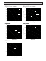
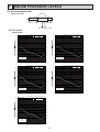
4 FAN PERFORMANCE AND CORRECTED AIR FLOW
PEAD-A24AA5
PEAD-A24AA5
(External static pressure 35Pa) 208-230V 60Hz
(External static pressure 100Pa) 208-230V 60Hz
60
[0.241]
150
[0.602]
Limit
Limit
External static pressure (Pa)[in.WG]
External static pressure (Pa)[in.WG]
50
[0.201]
40
[0.161]
Rated point
30
[0.120]
High
20
[0.080]
Middle
Rated point
100
[0.401]
High
Middle
50
[0.201]
Low
10
[0.040]
Low
0
[0] 10
[353]
15
[530]
20
[706]
Airflow rate
25
[883]
0
[0] 10
[353]
30
[1059]
15
[530]
(m3/min)[cfm]
20
[706]
Airflow rate
25
[883]
PEAD-A24AA5
PEAD-A24AA5
(External static pressure 50Pa) 208-230V 60Hz
(External static pressure 150Pa) 208-230V 60Hz
70
[0.281]
30
[1059]
(m3/min)[cfm]
200
[0.803]
60
[0.241]
Limit
External static pressure (Pa)[in.WG]
External static pressure (Pa)[in.WG]
Rated point
50
[0.201]
High
40
[0.161]
30
[0.120]
Middle
20
[0.080]
150
[0.602]
Rated point
Limit
High
100
[0.401]
Middle
50
[0.201]
Low
Low
10
[0.040]
0
[0] 10
[353]
15
[530]
20
[706]
25
[883]
0
[0] 10
[353]
30
[1059]
Airflow rate (m3/min)[cfm]
(External static pressure 70Pa) 208-230V 60Hz
90
[0.361]
80
[0.321]
External static pressure (Pa)[in.WG]
Rated point
Limit
60
[0.241]
High
50
[0.201]
40
[0.161]
Middle
30
[0.120]
20
[0.080]
Low
10
[0.040]
0
[0] 10
[353]
15
[530]
20
[706]
Airflow rate
20
[706]
Airflow rate (m3/min)[cfm]
PEAD-A24AA5
70
[0.281]
15
[530]
25
[883]
30
[1059]
(m3/min)[cfm]
6
25
[883]
30
[1059]
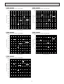
PEAD-A30AA5
PEAD-A30AA5
(External static pressure 35Pa) 208-230V 60Hz
(External static pressure 100Pa) 208-230V 60Hz
70
[0.281]
150
[0.602]
60
[0.241]
Limit
External static pressure (Pa)[in.WG]
External static pressure (Pa)[in.WG]
Limit
50
[0.201]
High
40
[0.161]
Rated point
Middle
30
[0.120]
20
[0.080]
High
Rated point
100
[0.401]
Middle
50
[0.201]
Low
Low
10
[0.040]
0
[0] 10
[353]
15
[530]
20
[706]
Airflow rate
25
[883]
0
[0] 10
[353]
30
[1059]
15
[530]
(m3/min)[cfm]
20
[706]
Airflow rate
25
[883]
PEAD-A30AA5
PEAD-A30AA5
(External static pressure 50Pa) 208-230V 60Hz
(External static pressure 150Pa) 208-230V 60Hz
200
[0.803]
90
[0.361]
80
[0.321]
High
High
Limit
External static pressure (Pa)[in.WG]
70
[0.281]
External static pressure (Pa)[in.WG]
30
[1059]
(m3/min)[cfm]
60
[0.241]
Rated point
50
[0.201]
Middle
40
[0.161]
30
[0.120]
Low
150
[0.602]
Rated point
Limit
Middle
100
[0.401]
Low
50
[0.201]
20
[0.080]
10
[0.040]
0
[0] 10
[353]
15
[530]
20
[706]
25
[883]
0
[0] 10
[353]
30
[1059]
PEAD-A30AA5
(External static pressure 70Pa) 208-230V 60Hz
100
[0.401]
90
[0.361]
High
External static pressure (Pa)[in.WG]
80
[0.321]
Limit
Rated point
70
[0.281]
Middle
60
[0.241]
50
[0.201]
40
[0.161]
Low
30
[0.120]
20
[0.080]
10
[0.040]
0
[0] 10
[353]
15
[530]
20
[706]
Airflow rate
15
[530]
20
[706]
Airflow rate (m3/min)[cfm]
Airflow rate (m3/min)[cfm]
25
[883]
30
[1059]
(m3/min)[cfm]
7
25
[883]
30
[1059]
PEAD-A36AA5
PEAD-A36AA5
(External static pressure 35Pa) 208-230V 60Hz
(External static pressure 100Pa) 208-230V 60Hz
70
[0.281]
150
[0.602]
Limit
Limit
High
50
[0.201]
External static pressure (Pa)[in.WG]
External static pressure (Pa)[in.WG]
60
[0.241]
40
[0.161]
Rated point
30
[0.120]
High
Middle
20
[0.080]
Rated point
100
[0.401]
Middle
50
[0.201]
Low
Low
10
[0.040]
0
[0] 10
[353]
15
[530]
20
[706]
25
[883]
30
[1059]
Airflow rate
35
[1236]
40
[1412]
0
[0] 10
[353]
45
[1589]
15
[530]
20
[706]
(m3/min)[cfm]
25
[883]
Airflow rate
30
[1059]
PEAD-A36AA5
PEAD-A36AA5
(External static pressure 50Pa) 208-230V 60Hz
(External static pressure 150Pa) 208-230V 60Hz
90
[0.361]
45
[1589]
High
Limit
External static pressure (Pa)[in.WG]
External static pressure (Pa)[in.WG]
40
[1412]
200
[0.803]
100
[0.401]
80
[0.321]
35
[1236]
(m3/min)[cfm]
70
[0.281]
High
60
[0.241]
Rated point
50
[0.201]
Middle
40
[0.161]
30
[0.120]
Low
Rated point
150
[0.602]
Limit
Middle
100
[0.401]
Low
50
[0.201]
20
[0.080]
10
[0.040]
0
[0] 10
[353]
15
[530]
20
[706]
25
[883]
30
[1059]
35
[1236]
40
[1412]
0
[0] 10
[353]
45
[1589]
PEAD-A36AA5
(External static pressure 70Pa) 208-230V 60Hz
150
[0.602]
External static pressure (Pa)[in.WG]
Limit
100
[0.401]
High
Rated point
Middle
50
[0.201]
0
[0] 10
[353]
Low
15
[530]
20
[706]
25
[883]
Airflow rate
30
[1059]
15
[530]
20
[706]
25
[883]
30
[1059]
Airflow rate (m3/min)[cfm]
Airflow rate (m3/min)[cfm]
35
[1236]
40
[1412]
45
[1589]
(m3/min)[cfm]
8
35
[1236]
40
[1412]
45
[1589]
PEAD-A42AA5
PEAD-A42AA5
(External static pressure 35Pa) 208-230V 60Hz
(External static pressure 100Pa) 208-230V 60Hz
70
[0.281]
200
[0.803]
Limit
Limit
High
60
[0.241]
External static pressure (Pa)[in.WG]
External static pressure (Pa)[in.WG]
Middle
50
[0.201]
Low
40
[0.161]
Rated point
30
[0.120]
20
[0.080]
150
[0.602]
High
Middle
100
[0.401]
Rated point
Low
50
[0.201]
10
[0.040]
0
[0] 15
[530]
20
[706]
25
[883]
30
[1059]
Airflow rate
35
[1236]
40
[1412]
0
[0] 15
[530]
45
[1589]
20
[706]
(m3/min)[cfm]
25
[883]
30
[1059]
Airflow rate
35
[1236]
PEAD-A42AA5
PEAD-A42AA5
(External static pressure 50Pa) 208-230V 60Hz
(External static pressure 150Pa) 208-230V 60Hz
Limit
High
200
[0.803]
External static pressure (Pa)[in.WG]
80
[0.321]
External static pressure (Pa)[in.WG]
45
[1589]
250
[1.004]
100
[0.401]
90
[0.361]
40
[1412]
(m33/min)[cfm]
70
[0.281]
Middle
60
[0.241]
50
[0.201]
Rated point
Low
40
[0.161]
30
[0.120]
20
[0.080]
High
Limit
150
[0.602]
Rated point
Middle
100
[0.401]
Low
50
[0.201]
10
[0.040]
0
[0] 15
[530]
20
[706]
25
[883]
30
[1059]
35
[1236]
40
[1412]
0
[0] 15
[530]
45
[1589]
PEAD-A42AA5
(External static pressure 70Pa) 208-230V 60Hz
150
[0.602]
Limit
External static pressure (Pa)[in.WG]
High
100
[0.401]
Middle
Rated point
50
[0.201]
0
[0] 15
[530]
Low
20
[706]
25
[883]
30
[1059]
Airflow rate
20
[706]
25
[883]
30
[1059]
35
[1236]
Airflow rate (m33/min)[cfm]
Airflow rate (m33/min)[cfm]
35
[1236]
40
[1412]
45
[1589]
(m33/min)[cfm]
9
40
[1412]
45
[1589]
PEAD-A24, 30, 36,42AA5
Air filter 208-230V 60Hz
15
[0.060]
External static pressure (Pa)[in.WG]
A36,42
10
[0.040]
A24,30
5
[0.020]
0
[0] 0
[0]
10
[353]
20
[706]
Airflow rate
30
[1059]
40
[1412]
(m3/min)[cfm]
10
5 SOUND PRESSURE LEVELS
5-1. Sound pressure level
Ceiling concealed
Aux. duct
test unit
2m
1.5m
1m
Measurement location
5-2. NC curves
PEAD-A24AA5
External static pressure 0.14 [in.WG] (35Pa)
70.0
High
Middle
65.0
External static pressure 0.40 [in.WG] (100Pa)
70.0
Low
High
Middle
65.0
60.0
Low
60.0
NC-60
55.0
NC-60
55.0
50.0
50.0
NC-50
45.0
NC-50
45.0
40.0
40.0
NC-40
NC-40
35.0
35.0
30.0
30.0
NC-30
NC-30
25.0
25.0
20.0
20.0
NC-20
15.0
5.0
NC-20
15.0
Approximate minimum
audible limit on
continuous noise
10.0
Approximate minimum
audible limit on
continuous noise
10.0
5.0
0.0
0.0
63
125
250
500
1k
2k
Octave band center frequencies (Hz)
4k
8k
63
External static pressure 0.20 [in.WG] (50Pa)
70.0
High
Middle
65.0
125
250
500
1k
2k
Octave band center frequencies (Hz)
8k
External static pressure 0.60 [in.WG] (150Pa)
70.0
Low
High
Middle
65.0
60.0
4k
Low
60.0
NC-60
55.0
NC-60
55.0
50.0
50.0
NC-50
45.0
NC-50
45.0
40.0
40.0
NC-40
NC-40
35.0
35.0
30.0
30.0
NC-30
NC-30
25.0
25.0
20.0
20.0
NC-20
15.0
5.0
NC-20
15.0
Approximate minimum
audible limit on
continuous noise
10.0
Approximate minimum
audible limit on
continuous noise
10.0
5.0
0.0
0.0
63
125
250
500
1k
2k
Octave band center frequencies (Hz)
4k
8k
63
External static pressure 0.28 [in.WG] (70Pa)
70.0
High
Middle
65.0
Low
60.0
NC-60
55.0
50.0
NC-50
45.0
40.0
NC-40
35.0
30.0
NC-30
25.0
20.0
NC-20
15.0
Approximate minimum
audible limit on
continuous noise
10.0
5.0
0.0
63
125
250
500
1k
2k
Octave band center frequencies (Hz)
4k
8k
11
125
250
500
1k
2k
Octave band center frequencies (Hz)
4k
8k
PEAD-A30AA5
External static pressure 0.14 [in.WG] (35Pa)
70.0
High
Middle
65.0
External static pressure 0.40 [in.WG] (100Pa)
70.0
Low
High
Middle
65.0
60.0
Low
60.0
NC-60
55.0
NC-60
55.0
50.0
50.0
NC-50
45.0
NC-50
45.0
40.0
40.0
NC-40
NC-40
35.0
35.0
30.0
30.0
NC-30
NC-30
25.0
25.0
20.0
20.0
NC-20
15.0
10.0
5.0
NC-20
15.0
Approximate minimum
audible limit on
continuous noise
Approximate minimum
audible limit on
continuous noise
10.0
5.0
0.0
0.0
63
125
250
500
1k
2k
Octave band center frequencies (Hz)
4k
8k
63
External static pressure 0.20 [in.WG] (50Pa)
70.0
High
Middle
65.0
125
250
500
1k
2k
Octave band center frequencies (Hz)
8k
External static pressure 0.60 [in.WG] (150Pa)
70.0
Low
High
Middle
65.0
60.0
4k
Low
60.0
NC-60
55.0
NC-60
55.0
50.0
50.0
NC-50
45.0
NC-50
45.0
40.0
40.0
NC-40
NC-40
35.0
35.0
30.0
30.0
NC-30
NC-30
25.0
25.0
20.0
20.0
NC-20
15.0
Approximate minimum
audible limit on
continuous noise
10.0
5.0
NC-20
15.0
Approximate minimum
audible limit on
continuous noise
10.0
5.0
0.0
0.0
63
125
250
500
1k
2k
Octave band center frequencies (Hz)
4k
8k
63
External static pressure 0.28 [in.WG] (70Pa)
70.0
High
Middle
65.0
Low
60.0
NC-60
55.0
50.0
NC-50
45.0
40.0
NC-40
35.0
30.0
NC-30
25.0
20.0
NC-20
15.0
Approximate minimum
audible limit on
continuous noise
10.0
5.0
0.0
63
125
250
500
1k
2k
Octave band center frequencies (Hz)
4k
8k
12
125
250
500
1k
2k
Octave band center frequencies (Hz)
4k
8k
PEAD-A36AA5
External static pressure 0.14 [in.WG] (35Pa)
70.0
High
Middle
65.0
External static pressure 0.40 [in.WG] (100Pa)
70.0
Low
High
Middle
65.0
60.0
Low
60.0
NC-60
55.0
NC-60
55.0
50.0
50.0
NC-50
45.0
NC-50
45.0
40.0
40.0
NC-40
NC-40
35.0
35.0
30.0
30.0
NC-30
NC-30
25.0
25.0
20.0
20.0
NC-20
15.0
10.0
5.0
NC-20
15.0
Approximate minimum
audible limit on
continuous noise
Approximate minimum
audible limit on
continuous noise
10.0
5.0
0.0
0.0
63
125
250
500
1k
2k
Octave band center frequencies (Hz)
4k
8k
63
External static pressure 0.20 [in.WG] (50Pa)
70.0
High
Middle
65.0
125
250
500
1k
2k
Octave band center frequencies (Hz)
8k
External static pressure 0.60 [in.WG] (150Pa)
70.0
Low
High
Middle
65.0
60.0
4k
Low
60.0
NC-60
55.0
NC-60
55.0
50.0
50.0
NC-50
45.0
NC-50
45.0
40.0
40.0
NC-40
NC-40
35.0
35.0
30.0
30.0
NC-30
NC-30
25.0
25.0
20.0
20.0
NC-20
15.0
Approximate minimum
audible limit on
continuous noise
10.0
5.0
NC-20
15.0
Approximate minimum
audible limit on
continuous noise
10.0
5.0
0.0
0.0
63
125
250
500
1k
2k
Octave band center frequencies (Hz)
4k
8k
63
External static pressure 0.28 [in.WG] (70Pa)
70.0
High
Middle
65.0
Low
60.0
NC-60
55.0
50.0
NC-50
45.0
40.0
NC-40
35.0
30.0
NC-30
25.0
20.0
NC-20
15.0
Approximate minimum
audible limit on
continuous noise
10.0
5.0
0.0
63
125
250
500
1k
2k
Octave band center frequencies (Hz)
4k
8k
13
125
250
500
1k
2k
Octave band center frequencies (Hz)
4k
8k
PEAD-A42AA5
External static pressure 0.14 [in.WG] (35Pa)
70.0
High
Middle
65.0
External static pressure 0.40 [in.WG] (100Pa)
70.0
Low
High
Middle
65.0
60.0
Low
60.0
NC-60
55.0
NC-60
55.0
50.0
50.0
NC-50
45.0
NC-50
45.0
40.0
40.0
NC-40
NC-40
35.0
35.0
30.0
30.0
NC-30
NC-30
25.0
25.0
20.0
20.0
NC-20
15.0
10.0
5.0
NC-20
15.0
Approximate minimum
audible limit on
continuous noise
Approximate minimum
audible limit on
continuous noise
10.0
5.0
0.0
0.0
63
125
250
500
1k
2k
Octave band center frequencies (Hz)
4k
8k
63
External static pressure 0.20 [in.WG] (50Pa)
70.0
High
Middle
65.0
125
250
500
1k
2k
Octave band center frequencies (Hz)
8k
External static pressure 0.60 [in.WG] (150Pa)
70.0
Low
High
Middle
65.0
60.0
4k
Low
60.0
NC-60
55.0
NC-60
55.0
50.0
50.0
NC-50
45.0
NC-50
45.0
40.0
40.0
NC-40
NC-40
35.0
35.0
30.0
30.0
NC-30
NC-30
25.0
25.0
20.0
20.0
NC-20
15.0
Approximate minimum
audible limit on
continuous noise
10.0
5.0
NC-20
15.0
Approximate minimum
audible limit on
continuous noise
10.0
5.0
0.0
0.0
63
125
250
500
1k
2k
Octave band center frequencies (Hz)
4k
8k
63
External static pressure 0.28 [in.WG] (70Pa)
70.0
High
Middle
65.0
Low
60.0
NC-60
55.0
50.0
NC-50
45.0
40.0
NC-40
35.0
30.0
NC-30
25.0
20.0
NC-20
15.0
Approximate minimum
audible limit on
continuous noise
10.0
5.0
0.0
63
125
250
500
1k
2k
Octave band center frequencies (Hz)
4k
8k
14
125
250
500
1k
2k
Octave band center frequencies (Hz)
4k
8k
D(Duct)
66±3(2-5/8±1/8)
58(2-5/16)
40(1-5/8)
40(1-5/8)
78±3(3-1/8±1/8)
Air
outlet
32(1-5/16)
Piping
side view
1 Refrigerant piping (gas)
2X2-ø2.9(1/8)
67
136
356(14-1/16)
(2-11/16)
(5-3/8)
10(7/16)
12
0
Drain pump
Air
inlet
Top
Drain pipe(O.Dø32(1-1/4))(Gravity drain)
Terminal block(Power source)
Control box Bottom
Terminal block(Transmission)
Drain pipe
(Integral lift pump outlet)
(O.Dø32(1-1/4))
732(28-7/8)
700(27-9/16)
238(9-3/8)
643(25-3/8)
(Suspension bolt pitch)
ø125 6)
/1
(4-15
135
3-ø2.9(1/8) mount hole
18(3/4)
Fresh air intake ø100(3-15/16)
knock out hole
Note 4
153(6-1/16)
A
120
57(2-1/4)
10(7/16)
Top
view
2 Refrigerant piping(liquid)
20(13/16)
200(7-7/8)
Top
2XE-ø2.9(1/8)
378(14-15/16)
C
Drain pipe(O.D ø32(1-1/4)
(Emergency drain)
Bottom
100(3-15/16)X(E-1)=F
30(1-3/16)
15(5/8)
122(4-13/16)
33(1-5/16)
100(3-15/16)
(5-3/8)
41(1-5/8)
B(Suspension bolt pitch)
23(15/16)
Outlet air
side view
40(1-5/8)
100(3-15/16)
23(15/16)
(DUCT)
178(7-1/16)
217(8-9/16)
15
250(9-7/8)
G
210(8-5/16)
B
1154
(45-7/16)
1454
(57-1/4)
Air filter
Model
C
1200
(47-1/4)
1500
(59-1/16)
D
1060
(41-3/4)
1360
(53-9/16)
PEAD-A36,42AA5
PEAD-A24,30AA5
Inlet air
side view
14
11
E
F
1000
(39-3/8)
1300
(51-3/16)
ø15.88
(5/8)
Unit:mm(in.)
G
1058
(41-11/16)
1358
(53-1/2)
ø9.52
(3/8)
1 Gas pipe 2 Liquid pipe
Unit:mm(in.)
Note 1.Use an M10 screw for the suspension bolt (field supply).
2.Keep the service space for maintenance at the bottom.
3.If the inlet duct is used,remove the air filter
(supplied with the unit),then install the filter
(field supply) at the suction side.
4.Heat air to 0°C (32°F) or higher when taking fresh air
with a fresh air intake.
A
1100
PEAD-A24,30AA5 (43-5/16)
1400
PEAD-A36,42AA5 (55-1/8)
Model
21(7/8)
Opposite piping
side view
6 OUTLINES & DIMENSIONS
INDOOR UNIT
PEAD-A24, 30, 36, 42AA5
Access door 3
Supply air
B
Fig.3
Intake air
Intake air
Electric box
Ceiling
Ceiling
Ceiling beam
Access door 2(450X450)
(17-3/4X17-3/4) A
Fig.1
Ceiling beam
475(18-3/4)
777(30-5/8)
Access door 3
Bottom of
indoor unit
Intake
air
(17-3/4)
450
(11-13/16)
Maintenance
access space
of the arrow B)
777(30-5/8)
Access door 4
Bottom of
indoor unit
Electric box
700(27-9/16)
Intake
air
6(1/4)
of the arrow B)
Model
J
K
H
J
0
(2-9/16-7/16
) 65-100
(Actual length)
(11-13/16)
K L M N P
KX(L-1)=M
K
K
Unit:mm(in.)
Q
R
J
Drain hose(I.D ø32(1-1/4))
(Accessory)
Less than 300
(4-7/16)(4-7/16)
Maintenance
access space
250~350
1200 49 330
990
1100
1700
PEAD-A24,30AA5 (47-1/4) (1-15/16) (13) 4 (39) 10 (43-5/16) (9-7/8)~(13-13/16) (66-15/16)
400~500
2000
1500 54 320 5 1280 12 1400
PEAD-A36,48AA5 (59-1/16)
(2-3/16) (12-5/8) (50-7/16) (55-1/8) (15-3/4)~(19-11/16) (78-3/4)
(11-13/16)
Min. 300mm
N-ø2.9(1/8)
Fig.5 (Viewed from the direction
Supply
air
Min. 300mm 50(2)
Fig.4 (Viewed from the direction
Supply
air
Electric box
475(18-3/4)
50(2) 700(27-9/16)
Access door 1
(450X450)
(17-3/4X17-3/4)
Maintenance
access space
Intake
air
(17-3/4)
450
(11-13/16)
Min. 300mm
(Viewed from the direction
of the arrow A)
(17-3/4)
(2~5-15/16)
Fig.2
450
50~150
Supply
air
Bottom of
indoor unit
Access door 2 Electric box
(450X450)
(17-3/4X17-3/4)
Access door 1
(450X450)
(17-3/4X17-3/4)
(17-3/4)
Supply air
(11-13/16)
(13/16)
Min. 300mm
Min. 20mm
(7/16)
(7/16)
700(27-9/16)
450
P
50(2)
(17-3/4)
100~200
Q 450
(17-3/4)
100~200
Electric box
Min. 10mm
450
P
(3-15/16~7-7/8)
Min. 10mm
(2)When a space of less than 300mm is available below the unit between the unit and the ceiling.
(At least 20mm of space should be left below the unit as shown in Fig.3.)
• Create access door 1 diagonally below the electric box and access door 3 below the unit as shown in Fig.4.
or
• Create access door 4 below the electric box and the unit as shown in Fig.5.
(1)When a space of 300mm or more is available below the unit between the unit and the ceiling. (Fig.1)
• Create access door 1 and 2 (450x450mm each) as shown in Fig.2.
(Access door 2 is not required if enough space is available below the unit for a maintenance worker to work in.)
H
(3-15/16~7-7/8)
R
Less than 700(27-9/16)
112 112 11(7/16)
[Maintenance access space]
Secure enough access space to allow for the maintenance, inspection, and replacement of the motor, fan, drain pump, heat exchanger,
and electric box in one of the following ways.
Select an installation site for the indoor unit so that it's maintenance access space will not be obstructed by beams or other objects.
P
50(2)
16
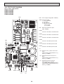
7 WIRING DIAGRAM
PEAD-A24, 30, 36, 42AA5
RFI
INSIDE SECTION OF CONTROL BOX
TB15
1
2
ACL
2
CN32
5
1 (BLUE) SW1
3 CN3C
(RED)
CN105
(RED)
CNER
CN25
CN4F
1
4
(RED)
CN2L
(YELLOW)
CN24-1
(RED)
CN20
1
2
CNXB2
1
5
5
F01
ZNR02
(BLUE) 2
CN22 1
U
ZNR01
CN51
(BLACK) (BLUE)
CN24-2
CN2C
4
3
(RED)
5 CND
ON
LED3
CN44
1
9
R.B.
TO OUTDOOR
UNIT
DSA
SWE
SW5
9
(GREEN)
CNF
1
LED2 (BLACK)
CN2A
OFF
TB6
1
2
P.B.
1
CN41
SW2
CN90
1
TB4
S1
S2
S3
1
2
1
2
5
I.B.
TRANSMISSION
WIRES
DC12V
U
LED1 (BLUE)
CNXA2
4
CNXC2
1
2
1
2
(BLUE)
CNP
1
X01
X10
DC280-340V
RECTIFIER
CIRCUIT
- +
3
4
CNXB1
1
5
(BLUE)
CNXC1 CNXA1
4
1 2 1
CNMF
7
4
1
MODEL
SW1
SW2
SW5
ON
ON
ON
12345
ON
12345
ON
12345678
ON
12345
ON
12345
ON
12345678
ON
12345
ON
12345
ON
12345678
ON
12345
12345
12345678
PEAD-A24AA5
1
BZ1
9
CN1
PEAD-A30AA5
LED1
RU
SW1 SW2
W.B.
t˚
t˚
TH2 TH5
t˚
FS
TH1
MS
3~
M
1~
DRAINPUMP
FAN MOTOR
PEAD-A36AA5
PEAD-A42AA5
The black square( ) indicates a switch position.
SYMBOL EXPLANATION
SYMBOL
NAME
SYMBOL
NAME
SYMBOL
NAME
I.B.
INDOOR CONTROLLER BOARD
TERMINAL BLOCK
I.B.
INDOOR CONTROLLER BOARD
TB4
(INDOOR/OUTDOOR CONNECTING LINE)
CN24-1 CONNECTOR (HEATER CONTROL 1ST)
SW1 SWITCH (FOR MODEL SELECTION)
CN24-2 CONNECTOR (HEATER CONTROL 2ND)
SW2 SWITCH (FOR CAPACITY CODE)
TERMINAL BLOCK
TB5
(REMOTE CONTROLLER TRANSMISSION LINE)
CN25 CONNECTOR (HUMIDITY OUTPUT)
SW5 SWITCH (FOR MODE SELECTION)
CN2A CONNECTOR (0-10V ANALOG INPUT)
SWE CONNECTOR (EMERGENCY OPERATION) OPTIONAL PARTS
IR WIRELESS REMOTE CONTROLLER BOARD
CN2C CONNECTOR (ERV OUTPUT)
P.B.
POWER SUPPLY BOARD
W.B.
CN2L CONNECTOR (LOSSNAY)
F01 FUSE AC250V 6.3A
RU RECEIVING UNIT
CN32 CONNECTOR (REMOTE SWITCH)
BZ1 BUZZER
ZNR01,02 VARISTOR
DSA ARRESTOR
LED1 LED (RUN INDICATOR)
CN41 CONNECTOR (HA TERMINAL-A)
CN51 CONNECTOR (CENTRALLY CONTROL)
X01 AUX. RELAY
SW1 SWITCH (HEATING ON/OFF)
CN90 CONNECTOR (WIRELESS)
X10 AUX. RELAY
SW2 SWITCH (COOLING ON/OFF)
TH1
R.B.
WIRED REMOTE CONTROLLER BOARD
CN105 CONNECTOR (RADIOFREQUENCY INTERFACE)
INTAKE AIR TEMP.THERMISTOR
TH2
LED1 LED (POWER SUPPLY)
PIPE TEMP.THERMISTOR/LIQUID
TB6 TERMINAL BLOCK
TH5
(REMOTE CONTROLLER TRANSMISSION LINE)
LED2 LED (REMOTE CONTROLLER SUPPLY)
COND./EVA.TEMP.THERMISTOR
ACL
AC REACTOR (POWER FACTOR IMPROVEMENT)
LED3 LED (TRANSMISSION INDDOR-OUTDOOR)
CNER CONNECTOR (ERV INPUT)
FS
FLOAT SWITCH
RADIO FREQUENCY INTERFACE FOR RF THERMOSTAT
CNF CONNECTOR (HUMIDITY INPUT)
RFI
17
Note1.Since the outdoor side electric wiring may change be sure
to check the outdoor unit electric wiring for servicing.
2.Indoor and outdoor connecting wires are made with pola rities,
make wiring matching terminal numbers (S1,S2,S3).
3.Symbols used in wiring diagram above are as follows.
,
:CONNECTOR
:TERMINAL
(HEAVY DOTTED LINE):FIELD WIRING
(THIN DOTTED LINE):OPTIONAL PARTS
4.Use copper supply wire.
8 REFRIGERANT SYSTEM DIAGRAM
PEAD-A24, 30, 36, 42AA5
Strainer (#50)
Heat exchanger
Refrigerant GAS pipe connection
(Flare)
Thermistor TH5
(Cond./ Eva.temperature)
Refrigerant flow in cooling
Refrigerant flow in heating
Refrigerant LIQUID pipe connection
(Flare)
Thermistor TH1
(Room temperature)
Thermistor TH2
Pipe temperature(Liquid)
Distributor
with strainer (#50)
Strainer (#50)
18
9 HEATER CONTROL
9-1. CONTROL SPECIFICATIONS AND FUNCTION SETTING
Table 1 shows how the field-installed heater is controlled. Select the desired pattern in the table below, and set the
Function on the indoor units as shown in Table 1.
Table.1 [Function table]
Select unit numbers 01 to 03 or all units (AL [wired remote controller] / 07 [IR wireless remote controller])
$%%
$
& '(%'(!
4 )" " " " *+,%-$). *,--$-.
$%%
$
& /(%(!
4 )" 0 " " " *+,%-$). *,--$-.
$%%
$
& 1(%'(!
4 )" 0 " " " *+,%-$). *,--$-.
$%%
/(%(!
$
& 2(%(!
4 )" 0 " " " *+,%-$). *,--$-.
/(%(!
$
& '(%'(!
4 )" 0 " " " *+,%-$). *,--$-.
! " #
#! " #
3- " 19
9-2. FAN CONTROL
By setting the Mode No. 23 in the Function Table in section 9-1 to 2 and using CN4Y on the optional parts PAC-YU25HT, the
following patterns of fan control will become possible when [DEFROST] or [ERROR] is displayed.
Fan control patterns when [DEFROST] or [ERROR] is displayed
Use of CN4Y (PAC-YU25HT)
Heater is off.
Heater is installed in the duct.
Unused*
No heater is installed in the duct.
Used
Fan ON*1
Fan OFF
Fan ON*1
Fan OFF
Heater is on.
While the heater is on, the fan will operate at high speed regardless of the fan setting on the remote controller,
except when the unit is operated in the DEFROST mode or when the unit is in error.
* If a heater is installed in the duct, do not use CN4Y. By doing so, the fan will turn off when the heater is on,
which may result in fire.
*1 Fan speed setting
Mode
Setting
Heating Thermo-OFF
Very low
[DEFROST] or [ERROR]
Very low
STOP
Remote controller setting
Remote controller setting
Remote controller setting
Fan control
Initial setting
Mode no.
Setting
25
1
25
2
-
25
3
-
*Refer to the Installation Manual for function settings.
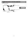
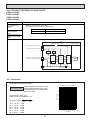
9-3. PAC-YU25HT (OPTIONAL PARTS) INSTALLATION
The following section describes installation of the External Heater Adapter that connects to PEAD-A AA5
series indoor unit. This products is the special wiring parts to drive an electric heater with the air conditioner.
(1) Parts list
Check that the following parts are included in the package.
1) External output cable (with a yellow connector).............................2 in total
Two types of cables with different connectors are included.
2) Panel heater connector.................................................................. 3 in total
White: 1
Green: 2 (2 types)
(2) Connection to the indoor unit
Use the cables that fit the connectors on the indoor unit control board.
1) External output cable (with a yellow connector)
This cable is used to connect a relay circuit for an interlocked operation with either an electric or a panel heater.
Connect the cable to CN24 on the indoor unit control board.
2) Panel heater connector (with a white connector)
This connector is used to perform an interlocked operation with a panel heater. Depending on the indoor unit
control board specification, connect the cable to CN4Y as appropriate
<Image>
CN4Y for FAN control
(PAC-YU25HT)
20
(3) Locally procured wiring
A basic connection method is shown below.
Electric Heater
power source
Remote control board
Relay circuit
Indoor unit
control board
Adapter
White
2
White
1
X
X
Electric Heater
or panel
heater
3
(applicable only when a panel
heater is connected)
CN4Y
White
1
Yellow
CN24
Red
Maximum cable length
is 10 m (32ft)
Preparations in the field
For relay X use the specifications given below Operation coil
Rated voltage: 12VDC
Power consumption: 0.9W or less
* Use the diode that is recommended by the relay manufacturer at both ends of the relay coil.
The length of the electrical wiring for the PAC-YU25HT is 2 meters (6-1/2 ft.)
To extend this length, use sheathed 2-core cable.
Control cable type: CVV, CVS, CPEV or equivalent.
Cable size: 0.5 mm2 ~ 1.25 mm2 (16 to 22 AWG)
Don't extend the cable more than 10 meters (32ft)
Recommended circuit
FS1
H1
88H
FS2
FS1
H2
88H
FS2
R
Wiring diagram
1-phase
power supply
S
208V, 230V/60Hz
R
S
FS1, 2 ----- Thermal fuse
26H
88H
Control board
H1, H2 ----- Heater
26H --------- Overheat
protection thermostat
88H --------- Electromagnetic contactor
CN24
(4) Wiring restrictions
Keep the length of the cable connecting to the circuit board of the indoor unit shorter than 10 meters (32ft).
Longer than 10 meters (32ft) could cause improper operation.
Use a transit relay when extending wiring such as remote wiring.
21
10 TROUBLESHOOTING
10-1. CAUTIONS ON TROUBLESHOOTING
(1) Before troubleshooting, check the followings:
1 Check the power supply voltage.
2 Check the indoor/outdoor connecting wire for mis-wiring.
(2) Take care the followings during servicing.
1 Before servicing the air conditioner, be sure to turn off the remote controller first to stop the main unit, and then turn
off the breaker.
2 When removing the indoor controller board, hold the edge of the board with care NOT to apply stress on the
components.
3 When connecting or disconnecting the connectors, hold the housing of the connector. DO NOT pull the lead wires.
Lead wires
22
10-2. SELF-CHECK FUNCTION
• Refer to the installation manual that comes with each remote controller for details.
• RF thermostat is not established.
[Output pattern A] Errors detected by indoor unit
IR wireless remote controller
Beeper sounds/OPERATION
INDICATOR lamp flashes
(Number of times)
1
2
3
4
5
6
7
8
9
10
11
12
No sound
Wired remote controller
RF thermostat
Symptom
Remark
Check code
P1
P2, P9
E6, E7
P4
P5
P6
EE
P8
E4
–
–
Fb
––
Intake sensor error
Pipe (Liquid or 2-phase pipe) sensor error
Indoor/outdoor unit communication error
Drain sensor error
Drain pump error
Freezing/Overheating safeguard operation
Communication error between indoor and outdoor units
Pipe temperature error
Remote controller signal receiving error
–
–
Indoor unit control system error (memory error, etc.)
No corresponding
[Output pattern B] Errors detected by unit other than indoor unit (outdoor unit, etc.)
IR wireless remote controller
Wired remote controller
RF thermostat
Symptom
Beeper sounds/OPERATION
INDICATOR lamp flashes
(Number of times)
1
2
3
4
5
6
7
8
9
10
E9
UP
U3, U4
UF
U2
U1, Ud
U5
U8
U6
U7
11
U9, UH
12
13
14
–
–
Others
Remark
Check code
Indoor/outdoor unit communication error (Transmitting error) (Outdoor unit)
Compressor overcurrent interruption
Open/short of outdoor unit thermistors
Compressor overcurrent interruption (When compressor locked)
Abnormal high discharging temperature/49C worked/ insufficient refrigerant
Abnormal high pressure (63H worked)/ Overheating safeguard operation
Abnormal temperature of heat sink
Outdoor unit fan protection stop
Compressor overcurrent interruption/Abnormal of power module
Abnormality of super heat due to low discharge temperature
Abnormality such as overvoltage or voltage shortage and abnormal
synchronous signal to main circuit/Current sensor error
–
–
Other errors (Refer to the technical manual for the outdoor unit.)
For details, check the LED
display of the outdoor controller
board.
*1 If the beeper does not sound again after the initial two beeps to confirm the self-check start signal was received and the OPERATION INDICATOR lamp does not
come on, there are no error records.
*2 If the beeper sounds three times continuously “beep, beep, beep (0.4 + 0.4 + 0.4 sec.)” after the initial two beeps to confirm the self-check start signal was
received, the specified refrigerant address is incorrect.
• On IR wireless remote controller
The continuous buzzer sounds from receiving section of indoor unit.
Blink of operation lamp
• On wired remote controller
Check code displayed on the LCD.
• If the unit cannot be operated properly after the above test run has been performed, refer to the following table to remove the cause.
Symptom
Cause
Wired remote controller
LED 1, 2 (PCB in outdoor unit)
• For about 2 minutes after power-on, operation of the
After
LED
1,
2
are
lighted,
LED
2
is
turned
For about 2 minutes
PLEASE WAIT
remote controller is not possible due to system start-up.
off, then only LED 1 is lighted. (Correct
following power-on
(Correct operation)
operation)
• Connector for the outdoor unit’s protection device is not
connected.
PLEASE WAIT → Error code
Only LED 1 is lighted. → LED 1, 2 blink.
• Reverse or open phase wiring for the outdoor unit’s power
After about 2 minterminal block (L1, L2, L3)
utes has expired
Display messages do not appear
following power-on
• Incorrect wiring between indoor and outdoor units
even when operation switch is
Only LED 1 is lighted. → LED 1, 2 blinks
(incorrect polarity of S1, S2, S3)
turned ON (operation lamp does
twice, LED 2 blinks once.
• Remote controller wire short
not light up).
On the IR wireless remote controller with conditions above, following phenomena takes place.
• No signals from the remote controller are accepted.
• OPE lamp is blinking.
• The buzzer makes a short ping sound.
Note:
Operation is not possible for about 30 seconds after cancellation of function selection. (Correct operation)
23
For description of each LED (LED1, 2, 3) provided on the indoor controller, refer to the following table.
LED 1 (power for microcomputer)
Indicates whether control power is supplied. Make sure that this LED is always lit.
LED 2 (power for remote controller)
Indicates whether power is supplied to the remote controller. This LED lights only in the case of
the indoor unit which is connected to the outdoor unit refrigerant address “0”.
LED 3 (communication between indoor and outdoor units)
Indicates state of communication between the indoor and outdoor units. Make sure that this LED is
always blinking.
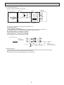
AUTO RESTART FUNCTION
Indoor controller board
This model is equipped with the AUTO RESTART FUNCTION.
When the indoor unit is controlled with the remote controller, the operation mode, set temperature, and the fan speed are memorized by the indoor controller board.
The auto restart function sets to work the moment the power has restored after power failure, then, the unit will restart automatically.
Set the AUTO RESTART FUNCTION using the wireless remote controller. (Mode no.1).
24
Note: Refer to the manual of outdoor unit for the details of display
such as F, U, and other E.
10-3. SELF-DIAGNOSIS ACTION TABLE
Error Code
P1
Abnormal point and detection method
Room temperature
thermistor (TH1)
1 The unit is in three-minute resume
prevention mode if short/open of
thermistor is detected. Abnormal if the
unit does not reset normally after three
minutes. (The unit returns to normal
operation, if it has normally reset.)
2 Constantly detected during cooling,
drying and heating operation
Short: 90˚C[194˚F] or more
Open: -40˚C[-40˚F] or less
Cause
1 Defective thermistor
characteristics
2 Contact failure of connector
(CN20) on the indoor controller
board (Insert failure)
3 Breaking of wire or contact
failure of thermistor wiring
4 Defective indoor controller
board
Countermeasure
1–3 Check resistance value of thermistor.
0:[32˚F].......15.0k"
10:[50˚F].....9.6k"
20:[68˚F].....6.3k"
30:[86˚F].....4.3k"
40:[104˚F]...3.0k"
If you put force on (draw or bend) the lead wire
with measuring resistance value of thermistor
breaking of wire or contact failure can be
detected.
2 Check contact failure of connector (CN20) on
the indoor controller board. Refer to 10-5.
Turn the power on again and check restart
after inserting connector again.
4 Check room temperature display on remote
controller.
Replace indoor controller board if there is
abnormal difference with actual room
temperature.
Turn the power off, and on again to operate
after check.
P2
Pipe temperature
thermistor/Liquid (TH2)
1 The unit is in three-minute resume
prevention mode if short/open of
thermistor is detected. Abnormal if the
unit does not reset normally after three
minutes. (The unit returns to normal
operation, if it has normally reset.)
2 Constantly detected during cooling,
drying, and heating (except defrosting)
operation.
Short: 90˚C[194˚F] or more
Open: -40˚C[-40˚F] or less
1 Defective thermistor
characteristics
2 Contact failure of connector
(CN44) on the indoor controller
board (Insert failure)
3 Breaking of wire or contact
failure of thermistor wiring
4 Defective refrigerant circuit is
causing thermistor temperature
of 90˚C[194˚F] or more or
-40˚C[-40˚F] or less.
5 Defective indoor controller board
1–3 Check resistance value of thermistor.
For characteristics, refer to (P1) above.
2 Check contact failure of connector (CN44) on
the indoor controller board. Refer to 10-5.
Turn the power on again and check restart
after inserting connector again.
4 Check pipe <liquid> temperature with remote
controller in test run mode. If pipe <liquid>
temperature is extremely low (in cooling
mode) or high (in heating mode), refrigerant
circuit may have defective.
5 Check pipe <liquid> temperature with remote
controller in test run mode. If there is extreme
difference with actual pipe <liquid> temperature,
replace indoor controller board.
Turn the power off, and on again to operate
after check.
P4
(5701)
P5
Contact failure of drain float switch (CN4F) 1 Contact failure of connector
1 Extract when the connector of drain float
(Insert failure)
switch is disconnected.
(3 and 4 of connector CN4F is not
short-circuited.)
2 Defective indoor controller
2 Constantly detected during operation.
board
Drain overflow protection operation
1 Suspensive abnormality, if drain float
switch is detected to be underwater for 1
minute and 30 seconds continuously
with drain pump on.
Turn off compressor and indoor fan.
2 Drain pump is abnormal if the condition
above is detected during suspensive
abnormality.
3 Constantly detected during drain pump
operation.
1 Malfunction of drain pump
2 Defective drain
Clogged drain pump
Clogged drain pipe
3 Defective drain float switch
Catch of drain float switch or
malfunction of moving parts
cause drain float switch to be
detected under water (Switch
On)
4 Defective indoor-controller
board
1 Check contact failure of float switch connector.
Turn the power on again and check after
inserting connector again.
2 Operate with connector (CN4F) short-circuited.
Replace indoor controller board if abnormality reappears.
1 Check if drain-up machine works.
2 Check drain function.
3 Remove drain float switch connector CN4F
and check if it is short (Switch On) with the
moving part of float switch UP, or OPEN with
the moving part of float switch down.
Replace float switch if it is short with the
moving part of float switch down.
4 Replace indoor controller board if it is shortcircuited between 3-4 of the drain float
switch connector CN4F and abnormality
reappears.
It is not abnormal if there is no problem about
the above-mentioned 1~4
Turn the power off, and on again to operate
after check.
25
Error Code
Abnormal point and detection method
Freezing/overheating protection is
working
1 Freezing protection (Cooling mode)
The unit is in six-minute resume prevention
mode if pipe <liquid or condenser/evaporator> temperature stays under
-15:[5˚F] for three minutes after the
compressor started. Abnormal if it stays
under -15:[5˚F] for three minutes again
within 16 minutes after six-minute
resume prevention mode.
2 Overheating protection (Heating mode)
The units is in six-minute resume
prevention mode if pipe <Liquid or condenser / evaporator> temperature is
detected as over 70:[158˚F] after the
compressor started. Abnormal if the
temperature of over 70:[158˚F] is
detected again within 10 minutes after
six-minute resume prevention mode.
P6
P8
Pipe temperature
<Cooling mode>
Detected as abnormal when the pipe temperature is not in the cooling range 3 minutes after compressor start and 6 minutes
after the liquid or condenser/evaporator pipe
is out of cooling range.
Note 1) It takes at least 9 minutes. to
detect.
Note 2) Abnormality P8 is not detected in
drying mode.
Cooling range :
-3 deg˚C(-5.4deg˚F) ] (TH-TH1)
TH: Lower temperature between: liquid
pipe temperature (TH2) and condenser/evaporator temperature (TH5)
TH1: Intake temperature
<Heating mode>
When 10 seconds have passed after the
compressor starts operation and the hot
adjustment mode has finished, the unit is
detected as abnormal when
condenser/evaporator pipe temperature is
not in heating range within 20 minutes.
Countermeasure
Cause
(Cooling or drying mode)
1 Clogged filter (reduced airflow)
2 Short cycle of air path
3 Low-load (low temperature)
operation beyond the tolerance
range
4 Defective indoor fan motor
• Fan motor is defective.
• Indoor controller board is
defective.
(Cooling or drying mode)
1 Check clogging of the filter.
2 Remove shields.
5 Defective outdoor fan control
6 Overcharge of refrigerant
7 Defective refrigerant circuit
(clogs)
5 Check outdoor fan motor.
67 Check operating condition of refrigerant
circuit.
(Heating mode)
1 Clogged filter (reduced airflow)
2 Short cycle of air path
3 Over-load (high temperature)
operation beyond the tolerance
range
4 Defective indoor fan motor
• Fan motor is defective.
• Indoor controller board is
defective.
(Heating mode)
1 Check clogs of the filter.
2 Remove shields.
5 Defective outdoor fan control
6 Overcharge of refrigerant
7 Defective refrigerant circuit
(clogs)
8 Bypass circuit of outdoor unit
is defective.
5 Check outdoor fan motor.
6~8Check operating condition of refrigerant
circuit.
1 Slight temperature difference
between indoor room
temperature and pipe <liquid
or condenser / evaporator>
temperature thermistor
• Shortage of refrigerant
• Disconnected holder of pipe
<liquid or condenser /
evaporator> thermistor
• Defective refrigerant circuit
2 Converse connection of
extension pipe (on plural units
connection)
3 Converse wiring of indoor/
outdoor unit connecting wire
(on plural units connection)
4 Defective detection of indoor
room temperature and pipe
<condenser / evaporator>
temperature thermistor
5 Stop valve is not opened
completely.
1~4
Note 3) It takes at least 27 minutes to
detect abnormality.
Note 4) It excludes the period of defrosting
(Detection restarts when defrosting mode is over)
Heating range :
3 deg˚C(5.4deg˚F) [ (TH5-TH1)
26
4 Refer to 10-8. DC Fan motor (FAN MOTOR/
INDOOR CONTROLLER BOARD)
4 Refer to 10-8. DC Fan motor (FAN MOTOR/
INDOOR CONTROLLER BOARD)
(
Check pipe <liquid or condenser /
evaporator> temperature with room
temperature display on remote
controller and outdoor controller circuit
board.
Pipe <liquid or condenser / evaporator>
temperature display is indicated by
setting SW2 of outdoor controller circuit
board as follows.
Conduct temperature check with outdoor
controller circuit board after connecting
‘A-Control Service Tool(PAC-SK52ST)’.
)
23Check converse connection of extension
pipe or converse wiring of indoor/outdoor
unit connecting wire.
Error Code
P9
Abnormal point and detection method
Cause
Countermeasure
Abnormality of pipe temperature thermistor / Condenser-Evaporator (TH5)
1 The unit is in three-minute resume protection mode if short/open of thermistor
is detected. Abnormal if the unit does
not get back to normal within three minutes. (The unit returns to normal operation, if it has normally reset.)
2 Constantly detected during cooling, drying, and heating operation (except
defrosting)
Short: 90˚C[194˚F] or more
Open: -40˚C[-40˚F] or less
1 Defective thermistor
characteristics
2 Contact failure of connector
(CN44) on the indoor controller
board (Insert failure)
3 Breaking of wire or contact
failure of thermistor wiring
4 Temperature of thermistor is
90:[194˚F] or more or
-40˚C[-40˚F] or less caused by
defective refrigerant circuit.
5 Defective indoor controller
board
1–3 Check resistance value of thermistor.
For characteristics, refer to (P1) above.
2 Check contact failure of connector (CN44)
on the indoor controller board.
Refer to 10-5.
Turn the power on and check restart after
inserting connector again.
4 Operate in test run mode and check pipe
<condenser / evaporator> temperature.
If pipe <condenser / evaporator> temperature is extremely low (in cooling mode) or
high (in heating mode), refrigerant circuit
may have defect.
5 When no problems are found in 1-4 above,
replace the indoor unit control board.
Remote controller transmission
error(E0)/signal receiving error(E4)
1 Abnormal if main or sub remote controller can not receive normally any
transmission from indoor unit of refrigerant address “0” for three minutes.
(Error code : E0)
2 Abnormal if sub remote controller could
not receive for any signal for two minutes. (Error code: E0)
E0
or
E4
1 Contact failure at transmission
wire of remote controller
2 All remote controllers are set
as “sub” remote controller. In
this case, E0 is displayed on
remote controller, and E4 is
displayed at LED (LED1, LED2)
on the outdoor controller circuit
board.
3 Mis-wiring of remote controller
4 Defective transmitting receiving
circuit of remote controller
1 Abnormal if indoor controller board can
not receive normally any data from
5 Defective transmitting receiving
remote controller board or from other
circuit of indoor controller board
indoor controller board for three minutes.
of refrigerant address “0”
(Error code: E4)
6 Noise has entered into the
transmission wire of remote
2 Indoor controller board cannot receive
any signal from remote controller for two
controller.
minutes. (Error code: E4)
Remote controller transmission
error(E3)/signal receiving error(E5)
1 Abnormal if remote controller could not
find blank of transmission path for six
seconds and could not transmit.
(Error code: E3)
2 Remote controller receives transmitted
data at the same time, compares the
data, and when detecting it, judges
different data to be abnormal 30
continuous times. (Error code: E3)
E3
or
E5
1 Two remote controller are set
as “main.”
(In case of 2 remote controllers)
2 Remote controller is connected
with two indoor units or more.
3 Repetition of refrigerant
address
4 Defective transmitting receiving
circuit of remote controller
1 Abnormal if indoor controller board could
5 Defective transmitting receiving
not find blank of transmission path.
circuit of indoor controller
(Error code: E5)
board
2 Indoor controller board receives transmitted data at the same time, compares 6 Noise has entered into transthe data,and when detecting it, judges
mission wire of remote condifferent data to be abnormal 30
troller.
continuous times. (Error code: E5)
27
1 Check disconnection or looseness of indoor
unit or transmission wire of remote controller.
2 Set one of the remote controllers “main”.
If there is no problem with the action above.
3 Check wiring of remote controller.
• Total wiring length: max.500m
(Do not use cable ✕ 3 or more)
• The number of connecting indoor units:
max.16units
• The number of connecting remote controller: max.2units
When it is not the above-mentioned problem of
1~3
4 Diagnose remote controllers.
a) When “RC OK” is displayed,
Remote controllers have no problem.
Turn the power off, and on again to check.
If abnormality generates again, replace
indoor controller board.
b) When “RC NG” is displayed,
Replace remote controller.
c) When “RC E3” is displayed,
d) When “ERC 00-06” is displayed,
[ c),d)→Noise may be causing abnormality. ]
∗ If the unit is not normal after replacing
indoor controller board in group control,
indoor controller board of address “0”
may be abnormal.
1 Set a remote controller to main, and the
other to sub.
2 Remote controller is connected with only one
indoor unit.
3 The address changes to a separate setting.
4~6 Diagnose remote controller.
a) When “RC OK”is displayed, remote controllers have no problem.
Turn the power off,and on again to check.
When becoming abnormal again, replace
indoor controller board.
b)When “RC NG”is displayed, replace
remote controller.
c)When “RC E3”or “ERC 00-66”is displayed,
noise may be causing abnormality.
Error Code
Abnormal point and detection method
E6
Indoor/outdoor unit communication
error (Signal receiving error)
1 Abnormal if indoor controller board
cannot receive any signal normally for
six minutes after turning the power on.
2 Abnormal if indoor controller board
cannot receive any signal normally for
three minutes.
3 Consider the unit as abnormal under the
following condition: When two or more
indoor units are connected to an
outdoor unit, indoor controller board
cannot receive a signal for three minutes
from outdoor controller circuit board, a
signal which allows outdoor controller
circuit board to transmit signals.
E7
Indoor/outdoor unit communication
1 Defective transmitting receiving 1-3 Turn the power off, and on again to check.
error (Transmitting error)
circuit of indoor controller board
If abnormality generates again, replace
Abnormal if “1” receiving is detected 30
indoor controller board.
2 Noise has entered into power
times continuously though indoor controller
supply.
board has transmitted “0”.
3 Noise has entered into outdoor
control wire.
Fb
Indoor controller board
Abnormal if data cannot be read normally
from the nonvolatile memory of the indoor
controller board.
E1
or
E2
1 Defective indoor controller
board
Remote controller control board
1 Defective remote controller
1 Abnormal if data cannot be read normally from the nonvolatile memory of the
remote controller control board.
(Error code: E1)
1 Replace indoor controller board.
1 Replace remote controller.
2 Abnormal if the clock function of remote
controller cannot be operated normally.
(Error code: E2)
Water leakage
This detection is performed during the
operation (stop, heating, fan, or error stop
mode etc.) other than cooling and dry.
1 When a) and b) are found, water leakage
occurs.
a) Pipe <liquid> temperature - inlet temperature < -10˚C for 30 minutes
b) When drain float switch is detected to
be soaked in the water for 15 minutes
or more.
* When drain float switch is detected to
be NOT soaked in the water, each
counting of a) and b) is cleared.
PA
(2500)
Countermeasure
Cause
1 Contact failure, short circuit or, ∗ Check LED display on the outdoor control circuit board. (Connect A-control service tool,
mis-wiring (converse wiring) of
PAC-SK52ST.)
indoor/outdoor unit connecting
Refer to EA-EC item if LED displays EA-EC.
wire
1 Check disconnection or looseness of indoor/
2 Defective transmitting receiving
outdoor unit connecting wire of indoor unit or
circuit of indoor controller board
outdoor unit.
3 Defective transmitting receiving
Check all the units in case of twin triple
circuit of indoor controller board
indoor unit system.
4 Noise has entered into indoor/ 2-4 Turn the power off, and on again to check.
If abnormality generates again, replace
outdoor unit connecting wire.
indoor controller board or outdoor
controller circuit board.
∗ Other indoor controller board may have
defect in case of twin triple indoor unit
system.
*When this error is detected, the error
will not be reset until the main power is
reset.
1 Mis-piping of extension pipes 1Check the extension pipes for mis-piping.
(When connected with multiple
units)
2 Mis-wiring of indoor/outdoor
unit connecting wire (When
connected with multiple units)
2Check the Indoor/outdoor unit connecting
wire for mis-wiring.
3 Detection failure of the indoor 3Check room temperature display on remote
unit inlet/pipe <liquid> thermiscontroller and indoor pipe <liquid> temperator
ture. (Refer to the countermeasure on P2.)
4 Drain pump failure
4Check if drain-up machine works.
5 Drainage failure
· Clogged drain pump
· Clogged drain pipe
5 Check drain function.
6 Drain float switch failure
6Check drain float switch. (Refer to the coun· Drain float switch is detected
termeasure on P4 and P5.)
to be soaked in the water (ON
status) due to the operation
failure of the moving parts.
· Contact failure of drain float
switch connector
(Loose connector)
28
10-4. TROUBLESHOOTING BY INFERIOR PHENOMENA
Note: Refer to the manual of outdoor unit for the detail of remote
controller.
Phenomena
(1)LED2 on indoor controller board
is off.
Cause
• When LED1 on indoor controller board is also off.
1 Power supply of rated voltage is not supplied to outdoor unit.
2 Defective outdoor controller circuit board
3 Power supply of 208~230V is not supplied to indoor
unit.
4 Defective indoor controller board
(2)LED2 on indoor controller board
is blinking.
Countermeasure
1 Check the voltage of outdoor power
supply terminal block (L, N) or (L3, N).
• When AC 208~230V is not detected.
Check the power wiring to outdoor unit
and the breaker.
• When AC 208~230V is detected.
—Check 2 (below).
2 Check the voltage between outdoor
terminal block S1 and S2.
• When AC 208~230V is not detected.
Check the fuse on outdoor controller
circuit board.
Check the wiring connection.
• When AC 208~230V is detected.
—Check 3 (below).
3 Check the voltage between indoor terminal
block S1 and S2.
• When AC 208~230V is not detected.
Check indoor/outdoor unit connecting
wire for mis-wiring.
• When AC 208~230V is detected.
—Check 4 (below).
4 Check the fuse on indoor controller board.
Check the wiring connection.
If no problem are found, indoor controller
board is defective.
• When LED1 on indoor controller board is also blinking. Check indoor/outdoor unit connecting wire
Connection failure of indoor/outdoor unit connecting for connection failure.
wire
• When LED1 is lit.
1 Mis-wiring of remote controller wires
1 Check the connection of remote conUnder twin triple indoor unit system, 2 or more indoor
troller wires in case of twin triple indoor
units are wired together.
unit system. When 2 or more indoor units
are wired in one refrigerant system,
connect remote controller wires to one of
2 Refrigerant address for outdoor unit is wrong or not
those units.
set.
2 Check the setting of refrigerant address
Under grouping control system, there are some units
in case of grouping control system.
whose refrigerant address is 0.
If there are some units whose refrigerant
addresses are 0 in one group, set one of
the units to 0 using SW1 (3-6) on outdoor
3 Short-cut of remote controller wires
controller circuit board.
4 Defective remote controller
34 Remove remote controller wires and
check LED2 on indoor controller board.
• When LED2 is blinking, check the
short-cut of remote controller wires.
• When LED2 is lit, connect remote
controller wires again and:
if LED2 is blinking, remote controller
is defective; if LED2 is lit, connection
failure of remote controller terminal
block etc. has returned to normal.
29
10-5. TEST POINT DIAGRAM
10-5-1. Power supply board
PEAD-A24AA5
PEAD-A30AA5
PEAD-A36AA5
PEAD-A42AA5
CND
CND
Power supply voltage (208 - 230VAC)
CNMF Fan motor output
1 - 4: 310 - 340 VDC
5 - 4: 15 VDC
6 - 4: 0 - 6.5 VDC
7 - 4: Stop 0 or 15 VDC
Run 7.5 VDC
(0 - 15 pulse)
CNP
Drain-up mechanism output
(208 - 230VAC)
CNXA1
Connect to the indoor controller board
CNXB1
Connect to the indoor controller board
CNXC1
Connect to the indoor controller board
CNXA2
Connect to the indoor power board
CNP
CNXB2
Connect to the indoor power board
CNXC2
Connect to the indoor power board
(*1)
VFG Voltage on the (-) side of PC51 and
C25
(Same with the voltage between 7 (+)
and 4 (-) of CNMF)
VCC Voltage between the C25 pins 15
VDC
(Same with the voltage between 5 (+)
and 4 (-) of CNMF)
Vsp
CNXB1
CNXC1 CNXA1
PC51
(*1)
C53
(*1)
CNMF
C25
(*1)
30
Voltage between the C53 pins
0VDC (with the fan stopped)
1 - 6.5VDC (with the fan in operation)
(Same with the voltage between 6 (+)
and 4 (-) of CNMF)
10-5-2. Indoor controller board
PEAD-A24AA5
PEAD-A30AA5
PEAD-A36AA5
PEAD-A42AA5
CN105
CN22
SWE
Emergency operation
SW1
Model selection
CNXA2
SW2
Capacity setting
CNXC2
CN105 Radio frequency interface
CNXB2
CN32 Remote start/stop adapter
CN41
CN51
CN22 For MA remote controller cable connection
(10 - 13 VDC (Between 1 and 3.))
CN51 Centralized control
CN32
CN41 JAMA standard HA terminal A
CN2L
SWE
SW1
SW2
CN44 Thermistor
(liquid/condenser/evaporator
temperature)
CN24
CN20
CN4F Float thermistor
CN4F
CN24 Heater control (12VDC)
CN44
CN4Y For fan control
CN20 Thermistor (Inlet temperature)
CN3C Indoor-outdoor transmission
(0 - 24VDC)
CN90 Wireless remote controller
CNXA2
Connect to the indoor controller board
CN3C
CN4Y
CN90
CNXB2
Connect to the indoor controller board
CNXC2
Connect to the indoor controller board
CNXA1
Connect to the indoor power board
CNXB1
Connect to the indoor power board
CNXC1
Connect to the indoor power board
31
10-6. TROUBLE CRITERION OF MAIN PARTS
PEAD-A24AA5
PEAD-A30AA5
PEAD-A36AA5
PEAD-A42AA5
Part name
Check method and criterion
Room temperature
thermistor
(TH1)
Measure the resistance with a tester.
(Part temperature 10°C (50°F) ~ 30°C (86°F))
Pipe temperature
thermistor/liquid
(TH2)
Condenser/evaporator
temperature thermistor
(TH5)
Normal
Abnormal
4.3kΩ~9.6kΩ
Opened or short-circuited
Wiring diagram
Motor
Motor winding
Board with build-in motor
Vm (Power supply for motor)
Vcc (Power supply for control)
Regulator
Hall IC
Vsp (Speed command voltage)
Power
device
PG (Pulse output for rotation)
Pre
driver
GND
Current detecting resistor
10-7. Thermistor
<Thermistor Characteristic graph>
Thermistor R0=15k" ± 3%
Fixed number of B=3480k" ± 2%
Rt=15exp { 3480(
0°C (32°F)
10°C (50°F)
20°C (68°F)
25°C (77°F)
30°C (86°F)
40°C (104°F)
< Thermistor for lower temperature >
Room temperature thermistor (TH1)
Pipe temperature thermistor (TH2)
Condenser/evaporator temperature
thermistor (TH5)
1
273+t
50
40
Resistance (K")
Thermistor for
lower temperature
1
)}
273
15k"
9.6k"
6.3k"
5.2k"
4.3k"
3.0k"
30
20
10
0
-20 -10 0 10 20 30 40 50
-4 14 32 50 68 86 104 122
Temperature
32
(˚C)
˚F
10-8. DC FAN MOTOR (FAN MOTOR/INDOOR CONTROLLER BOARD)
Check method of DC fan motor (fan motor/indoor controller circuit board)
1 Notes
· High voltage is applied to the connecter (CNMF) for the fan motor. Give attention to the service.
· Do not pull out the connector (CNMF) for the motor with the power supply on.
(It causes trouble of the indoor controller circuit board and fan motor.)
2 Self check
Symptom : The indoor fan cannot turn around.
Check the fuse (FUSE) on indoor
controller board.
Yes
Did the fuse blow?
No
Wiring contact check
Contact of fan motor connector (CNMF)
Check the drain pump (DP)
Is the resistance between
terminals normal?
Yes
Replace indoor controller board (I.B).
Replace fan motor (MF).
No
Replace drain pump (DP).
No
Is there no contact failure?
Wiring recovery
Yes
Power supply check (Remove the connector (CNMF))
Measure the voltage in the indoor controller circuit board.
TEST POINT 1 : VDC (between 1 (+) and 4 (-) of the fan connector): VDC DC310~340V
TEST POINT 2 : VCC (between 5 (+) and 4 (-) of the fan connector): VCC DC15V
Is the voltage normal?
Yes
Measure the resistance of the fan motor.
No
Replace indoor
controller board.
Is the resistance of the fan motor
normal?(Refer to below table)
Yes
OK
END
Check the operation.
NG
Does the fan motor rotate smoothly?
Yes
No
No
Turn OFF the power supply and
connect the connector CNMF.
Turn ON the power supply and
measure the voltage of connector
CNMF while rotaing the motor by
the hand.
Replace the fan motor.
Does the voltage between pin 7 and pin 4
of connector CNMF repeat 0V and 5V?
Yes
Replace indoor controller board.
pin 1 - pin 4
∞
pin 5 - pin 4
50kΩ
pin 6 - pin 4
150kΩ
pin 7 - pin 4
∞
END
Check the operation of fan.
NG
NG
Resistance
Replace the fan motor.
Yes
OK
Check the operation of fan.
Measuring points
No
*To measure the resistance, connect
the negative (-) end of the tester to pin 4.
33
Replace indoor controller board.
OK
END
10-9. FUNCTIONS OF DIP SWITCH AND JUMPER WIRE
Each function is controlled by the dip switch and the jumper wire on control p.c. board.
SW1 and SW2 are equipped only for service parts.
Model setting and capacity setting are memorized in the nonvolatile memory of the control p.c. board of
the unit.
(Marks in the table below)
Jumper wire
Functions
Setting by the dip switch and jumper wire
Jumper wire (
: Short
: Open)
Remarks
For service board
SW1
Model
settings
1
2
3
4
5
ON
OFF
Service board
MODELS
1 2 3 4 5
PEAD-A24AA5
1 2 3 4 5
SW2
Capacity
settings
PEAD-A30AA5
1 2 3 4 5
PEAD-A36AA5
1 2 3 4 5
PEAD-A42AA5
J41
J42
Pair number
setting with
wireless
remote
controller
JP1
Unit type
setting
JP3
Indoor
controller
board type
setting
ON
OFF
ON
OFF
ON
OFF
ON
OFF
Wireless remote Control PCB setting
controller setting
J41
J42
0
1
2
3~9
Model
Without TH5
With TH5
JP1
Indoor controller board type
Factory shipment
Service parts
<Settings at time of factory shipment>
Wireless remote controller: 0
Control PCB: (for both J41 and J42)
Four pair number settings are supported.
The pair number settings of the wireless remote
controller and indoor control PCB (J41/J42) are
given in the table on the left.
(' ' in the table indicates the jumper line is disconnected.)
There is no jumper (JP1) because these models
have the cond./eva. temperature thermistor (TH5).
JP3
34
11 DISASSEMBLY PROCEDURE
Exercise caution when removing heavy parts.
PEAD-A24AA5
PEAD-A30AA5
PEAD-A36AA5
PEAD-A42AA5
1. Control box
1. Removing the control box cover
(1) Remove the two fixing screws on the cover (A)
to remove it.
• Tighten screws to a torque of 2.0±0.2 N·m.
(A)
Fig. 1
Fig. 2
2. Thermistor (Intake air)
1. Remove the control box cover according to the
procedure in section 1.
(1) Pull out the thermistor holder (B) and thermistor (C) on the control box.
(B),(C)
Fig. 3
35
Exercise caution when removing heavy parts.
3. Drainpan
1. Removing the filter and the bottom plate
(1) Push up the tab on the filter, and pull out the
filter in the direction of the arrow 1.
(2) Remove the fixing screws on the bottom plate
(D), (E) to remove it.
•Tighten screws to a torque of 1.4±0.2 N·m.
(D)
Fig. 4
2. Removing the drainpan
(1) Pull out the drain pan in the direction of the
arrow 2.
Note
•Drain the water out of the drain pan before
removing it.
Fig. 5
36
(E)
Exercise caution when removing heavy parts.
4. Thermistor (Condenser/evaporator)
(Liquid pipe)
1. Remove the drain pan according to the procedure in section 3.
2. Removing the Heat exchanger cover
(1) Remove the four fixing screws on the heat
exchanger cover (F) to remove it.
• Tighten screws to a torque of 1.4±0.2 N·m.
(F)
Fig. 6
3. Removing the thermistor
(1) Remove the thermistor (G) from the thermistor
holder (H) on the copper tube.
Thermistor size
Liquid pipe: ø8mm
Condenser/evaporator: ø6mm
(G),(H)
Fig. 7
37
Exercise caution when removing heavy parts.
5. Fan and fan motor
1. Removing the filter and the bottom plate
(1) Push down the tab on the filter, and pull out
the filter in the direction of the arrow 1.
(2) Remove the fixing screws on the bottom plate
(J) to remove it.
• Tighten screws to a torque of 1.4±0.2 N·m.
(J)
Fig. 8
2. Removing the fan casing (bottom half)
(1) Squeeze the tabs on the fan casing to remove
it in the direction of arrow 2.
Fig. 9
3. Removing the motor cable
(1) Remove the motor cable threw the rubber
bush.
4. Removing the fan motor and the Sirocco fan
(1) Remove the two motor fixing screws to
remove the motor and the Sirocco fan in the
direction of arrow 3.
• Tighten screws to a torque of 3.5±0.2 N·m.
Fig. 10
(2) Remove the four fan case fixing screws to
take the top half of the fan casing off.
• Tighten screws to a torque of 1.4±0.2 N·m.
Fig. 11
38
Exercise caution when removing heavy parts.
6. Heat exchanger
1. Remove the drain pan according to the procedure in section 3.
2. Remove the heat exchanger cover according to
the procedure in section 4.2.
3. Removing the cover
(1) Remove the five fixing screws on the cover (K)
to remove it.
• Tighten screws to a torque of 2.0±0.2 N·m.
(K)
Fig. 12
4. Removing the Heat exchanger
(1) Remove the fixing screws on the heat
exchanger (L) to remove it.
• Tighten screws to a torque of 1.4±0.2 N·m.
(L)
Fig. 13
39
http://Global.MitsubishiElectric.com
HWE14030
New publication effective Sep. 2014
Specifications subject to change without notice