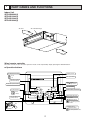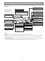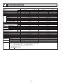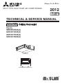
1
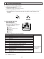
SPLIT-TYPE, HEAT PUMP AIR CONDITIONERS
2012
TECHNICAL & SERVICE MANUAL
Series SEZ
Model name
<Indoor unit>
SEZ-KD09NA(4)
SEZ-KD12NA(4)
SEZ-KD15NA(4)
SEZ-KD18NA(4)
INDOOR UNIT
TEMP.
ON/OFF
WIRED REMOTE CONTROLLER
CONTENTS
1. PART NAMES AND FUNCTIONS ···········································································2
2. SPECIFICATIONS ···································································································4
3. OUTLINES AND DIMENSIONS·············································································14
4. WIRING DIAGRAM ································································································15
5. REFRIGERANT SYSTEM DIAGRAM····································································17
6. HEATER CONTROL ······························································································18
7. TROUBLESHOOTING ···························································································21
8. DISASSEMBLY PROCEDURE··············································································34
1
PART NAMES AND FUNCTIONS
Indoor Unit
SEZ-KD09NA(4)
SEZ-KD12NA(4)
SEZ-KD15NA(4)
SEZ-KD18NA(4)
Air outlet
Air outlet duct flange
Air inlet
Wired remote controller
Once the controls are set, the same operation mode can be repeated by simply pressing the ON/OFF button.
●
Operation buttons
Start/Stop button
Set Temperature buttons
Down
Fan Speed button
Up
Timer Menu button
(Monitor/Set button)
Filter
button
(<return sign> button)
Mode button (Return button)
TEMP.
ON/OFF
Set Time buttons
Service button (Clear button)
Back
Ahead
Test Run button
MENU
BACK
MONITOR/SET
ON/OFF
FILTER
DAY
CHECK TEST
Airflow Up/Down button
Timer On/Off button
(Set Day button)
PAR-21MAA
OPERATION
CLOCK
CLEAR
Louver button
(
Operation button)
To preceding operation
number
Opening the
door
Ventilation button
Operation button)
(
To next operation number
2
● Display
“Sensor” indication
Displayed when the remote controller
sensor is used.
Day-of-Week
For purposes of this explanation,
all parts of the display are shown
as lit. During actual operation, only
the relevant items will be lit.
Shows the current day of the week.
Time/Timer Display
“Locked” indicator
Shows the current time (The 12 hour clock or The 24
hour clock), unless the simple or Auto Off timer is set.
If the simple or Auto Off timer is set, shows the time
remaining.
Indicates that remote controller buttons have been locked.
Identifies the current operation
“Clean The Filter” indicator
Shows the operating mode, etc.
* Multilanguage display is supported.
Comes on when it is time to clean the
filter.
TIME SUN MON TUE WED THU FRI SAT
TIMER
Hr
ON
AFTER
FUNCTION
FILTER
˚F˚C
“Centrally Controlled” indicator
Indicates that operation of the remote controller has been prohibited by a master controller.
Timer indicators
AFTER OFF
ERROR CODE
˚F˚C
The indicator comes on if the corresponding timer is set.
WEEKLY
SIMPLE
AUTO OFF
ONLY1Hr.
Fan Speed indicator
Shows the selected fan speed.
“Timer Is Off” indicator
Indicates that the timer is off.
Temperature Setting
Shows the target temperature.
Up/Down Air Direction indicator
Room Temperature display
Shows the room temperature.
The indicator
shows the direction of the outcoming airflow.
Louver display
“One Hour Only” indicator
Indicates the action of the swing
louver. Does not appear if the
louver is stationary.
Displayed if the airflow is set to
Low and downward during COOL
or DRY mode. (Operation varies
according to model.)
The indicator goes off after one
hour, at which time the airflow direction also changes.
Ventilation indicator
Appears when the unit is running in
Ventilation mode.
(Power On indicator)
Indicates that the power is on.
Caution
● Only the Power on indicator lights when the unit is stopped and power supplied to the unit.
● If you press a button for a feature that is not installed in the indoor unit, the remote controller will display the “Not Available”
message.
If you are using the remote controller to operate multiple indoor units, this message will appear only if the feature is not
present at the parent unit.
● When power is turned ON for the first time, it is normal that “PLEASE WAIT” is displayed on the room temperature indication
(For max. 2minutes). Please wait until this “PLEASE WAIT” indication disappears then start the operation.
3
2
SPECIFICATIONS
SEZ-KD09NA(4)
Model Name
Capacity
BTU/h
Power source
Power input
Current
Temperature set range Remote controller
Airflow direction
Fan
Type x Quantity
External static press
Motor type
Motor output
Driving mechanism
Airflow rate(Low-Mid-High)
Airflow rate(Low-Mid-High)
Airflow rate(Low-Mid-High)
External finish
External dimension
HxWxD
Net weight
Min.size of wire
Wiring
Amperage of wire breaker
R410A
Refrigerant
Liquid
piping diameter Gas
R410A
Drain piping diameter
Sound level (Low-Mid-High)
(measured in anechoic room)
Insulation material
Air filter
Refrigerant control device
Protection devices
Heat exchanger
Varistor
Terminal block
Power outlet
Document
Standard
Accessory
attachment
kW
A
˚F(˚C)
in.WG(Pa)
kW
m3/min
CFM
L/S
mm
In.
kg
in.(mm)
A
in.(mm)
in.(mm)
in.(mm)
dB<A>
A
Cooling
8100
SEZ-KD12NA(4)
Heating
10900
208/230V (60Hz)
0.06
0.04
0.51
0.39
67 to 86 (19 to 30)
63 to 83 (17 to 28)
Sirocco fan x 2
0.02-0.06-0.14-0.20 (5-15-35-50)
DC brushless motor
0.096
Direct-driven
5.5-7.0-9.0
194-247-317
91-116-150
Galvanized
200 x 790 x 700
7-7/8 x 31-1/8 x 27-9/16
18
1/8 (1.6)
15
ø1/4 (ø6.35) Flare
ø3/8 (ø9.52) Flare
O.D. 1-1/4 (32)
Cooling
11500
208/230V (60Hz)
0.07
0.05
0.57
0.46
67 to 86 (19 to 30)
63 to 83 (17 to 28)
Sirocco fan x 2
0.02-0.06-0.14-0.20 (5-15-35-50)
DC brushless motor
0.096
Direct-driven
7.0-9.0-11.0
247-317-388
116-150-183
Galvanized
200 x 990 x 700
7-7/8 x 39 x 27-9/16
21
1/8 (1.6)
15
ø1/4 (ø6.35) Flare
ø3/8 (ø9.52) Flare
O.D. 1-1/4 (32)
23-26-30
23-28-33
Polystyrene foam, Polyethylene foam, Urethane foam
PP Honeycomb fabric (washable)
Fuse (250V 6.3A)
Cross fin (Aluminum fin and copper tube)
ERZV10D471
To outdoor unit : 3P To wired remote controller : 2P
10
Installation Manual, Instruction Book
Polystyrene foam, Polyethylene foam, Urethane foam
PP Honeycomb fabric (washable)
Fuse (250V 6.3A)
Cross fin (Aluminum fin and copper tube)
ERZV10D471
To outdoor unit : 3P To wired remote controller : 2P
10
Installation Manual, Instruction Book
Drain hose (flexible joint), <Wired Remote Controller>
Drain hose (flexible joint), <Wired Remote Controller>
Remark
Note
Heating
13600
1.Cooling/Heating capacity indicates the maximum value at operation under the following condition.
Indoor:80˚FD.B. / 67˚FW.B. (26.7˚CD.B. / 19.4˚CW.B.) Outdoor:95˚FD.B. (35˚CD.B.)
Indoor:70˚FD.B. (21.1˚CD.B.) Outdoor:47˚FD.B. / 43˚FW.B. (8.3˚CD.B. / 6.1˚CW.B.)
Pipe length:24-9/16ft (7.5m)
Height difference:0ft (0m)
2.Power consumption. Run current at 0.06[in.WG] (15Pa) (external static pressure)
3.Cooling capacity value at 1:1system
Heating capacity value at 1:1system
4. < > SEZ-KD NA only
<Cooling>
<Heating>
4
SEZ-KD15NA(4)
Model Name
Capacity
BTU/h
Power source
Power input
Current
Temperature set range Remote controller
Airflow direction
Fan
Type x Quantity
External static press
Motor type
Motor output
Driving mechanism
Airflow rate(Low-Mid-High)
Airflow rate(Low-Mid-High)
Airflow rate(Low-Mid-High)
External finish
External dimension
HxWxD
Net weight
Min.size of wire
Wiring
Amperage of wire breaker
R410A
Refrigerant
Liquid
piping diameter Gas
R410A
Drain piping diameter
Sound level (Low-Mid-High)
(measured in anechoic room)
Insulation material
Air filter
Refrigerant control device
Protection devices
Heat exchanger
Varistor
Terminal block
Power outlet
Document
Standard
Accessory
attachment
kW
A
˚F(˚C)
in.WG(Pa)
kW
m3/min
CFM
L/S
mm
In.
kg
in.(mm)
A
in.(mm)
in.(mm)
in.(mm)
dB<A>
A
Cooling
14100
SEZ-KD18NA(4)
Cooling
17200
Heating
18000
208/230V (60Hz)
0.09
0.07
0.74
0.63
67 to 86 (19 to 30)
63 to 83 (17 to 28)
Sirocco fan x 3
0.02-0.06-0.14-0.20 (5-15-35-50)
DC brushless motor
0.096
Direct-driven
10.0-12.5-15.0
353-441-529
167-208-250
Galvanized
200 x 990 x 700
7-7/8 x 39 x 27-9/16
23
1/8 (1.6)
15
ø1/4 (ø6.35) Flare
ø1/2 (ø12.7) Flare
O.D. 1-1/4 (32)
208/230V (60Hz)
0.09
0.07
0.74
0.63
67 to 86 (19 to 30)
63 to 83 (17 to 28)
Sirocco fan x 4
0.02-0.06-0.14-0.20 (5-15-35-50)
DC brushless motor
0.096
Direct-driven
12.0-15.0-18.0
423-529-635
200-250-300
Galvanized
200 x 1190 x 700
7-7/8 x 46-7/8 x 27-9/16
27
1/8 (1.6)
15
ø1/4 (ø6.35) Flare
ø1/2 (ø12.7) Flare
O.D. 1-1/4 (32)
30-34-37
30-34-38
Polystyrene foam, Polyethylene foam, Urethane foam
PP Honeycomb fabric (washable)
Fuse (250V 6.3A)
Cross fin (Aluminum fin and copper tube)
ERZV10D471
To outdoor unit : 3P To wired remote controller : 2P
20
Installation Manual, Instruction Book
Polystyrene foam, Polyethylene foam, Urethane foam
PP Honeycomb fabric (washable)
Fuse (250V 6.3A)
Cross fin (Aluminum fin and copper tube)
ERZV10D471
To outdoor unit : 3P To wired remote controller : 2P
20
Installation Manual, Instruction Book
Drain hose (flexible joint), <Wired Remote Controller>
Drain hose (flexible joint), <Wired Remote Controller>
Remark
Note
Heating
21600
1.Cooling/Heating capacity indicates the maximum value at operation under the following condition.
Indoor:80˚FD.B. / 67˚FW.B. (26.7˚CD.B. / 19.4˚CW.B.) Outdoor:95˚FD.B. (35˚CD.B.)
Indoor:70˚FD.B. (21.1˚CD.B.) Outdoor:47˚FD.B. / 43˚FW.B. (8.3˚CD.B. / 6.1˚CW.B.)
Pipe length:24-9/16ft (7.5m)
Height difference:0ft (0m)
2.Power consumption. Run current at 0.06[in.WG] (15Pa) (external static pressure)
3.Cooling capacity value at 1:1system
Heating capacity value at 1:1system
4. < > SEZ-KD NA only
<Cooling>
<Heating>
5
SOUND CRITERION CURVES
<60Hz>
SEZ-KD09NA(4)
NOTCH SPL(dB)
High
29
Middle
25
Low
22
External static pressure:
0.02[in.WG](5Pa)
LINE
NC-70
60
NC-60
50
NC-50
40
NC-40
30
NC-30
APPROXIMATE
TERESHOLD OF
HEARING FOR
CONTINUOUS
NOISE
NC-20
OCTAVE BAND SOUND PRESSURE LEVEL, dB (0 dB = 0.0002 µbar)
OCTAVE BAND SOUND PRESSURE LEVEL, dB (0 dB = 0.0002 µbar)
70
10
80
70
NC-70
60
NC-60
50
NC-50
40
NC-40
30
NC-30
20
APPROXIMATE
TERESHOLD OF
HEARING FOR
CONTINUOUS
NOISE
NC-20
10
63
125
250
500
1000
2000
4000
8000
63
125
BAND CENTER FREQUENCIES, Hz
NOTCH SPL(dB)
High
31
Middle
28
Low
24
External static pressure:
0.14[in.WG](35Pa)
250
500
1000
2000
4000
8000
BAND CENTER FREQUENCIES, Hz
<60Hz>
SEZ-KD09NA(4)
LINE
<60Hz>
SEZ-KD09NA(4)
NOTCH SPL(dB)
High
33
Middle
29
Low
25
External static pressure:
0.20[in.WG](50Pa)
LINE
90
80
70
NC-70
60
NC-60
50
NC-50
40
NC-40
30
NC-30
APPROXIMATE
TERESHOLD OF
HEARING FOR
CONTINUOUS
NOISE
NC-20
OCTAVE BAND SOUND PRESSURE LEVEL, dB (0 dB = 0.0002 µbar)
90
OCTAVE BAND SOUND PRESSURE LEVEL, dB (0 dB = 0.0002 µbar)
LINE
90
80
20
NOTCH SPL(dB)
High
30
Middle
26
Low
23
External static pressure:
0.06[in.WG](15Pa)
90
20
<60Hz>
SEZ-KD09NA(4)
10
80
70
NC-70
60
NC-60
50
NC-50
40
NC-40
30
NC-30
20
APPROXIMATE
TERESHOLD OF
HEARING FOR
CONTINUOUS
NOISE
NC-20
10
63
125
250
500
1000
2000
4000
8000
63
BAND CENTER FREQUENCIES, Hz
125
250
500
1000
2000
4000
8000
BAND CENTER FREQUENCIES, Hz
NOTE: The sound level is measured in an anechoic room where echoes are few, when compressor stops. The sound
may be bigger than displayed level under actual installation condition by surrounding echoes. The sound level
can be higher by about 2 dB than the displayed level during cooling and heating operation.
6
<60Hz>
SEZ-KD12NA(4)
NOTCH SPL(dB)
High
33
Middle
28
Low
23
External static pressure:
0.02[in.WG](5Pa)
LINE
NC-70
60
NC-60
50
NC-50
40
NC-40
30
NC-30
APPROXIMATE
TERESHOLD OF
HEARING FOR
CONTINUOUS
NOISE
NC-20
OCTAVE BAND SOUND PRESSURE LEVEL, dB (0 dB = 0.0002 µbar)
OCTAVE BAND SOUND PRESSURE LEVEL, dB (0 dB = 0.0002 µbar)
70
10
80
70
NC-70
60
NC-60
50
NC-50
40
NC-40
30
NC-30
20
APPROXIMATE
TERESHOLD OF
HEARING FOR
CONTINUOUS
NOISE
NC-20
10
63
125
250
500
1000
2000
4000
8000
63
125
BAND CENTER FREQUENCIES, Hz
NOTCH SPL(dB)
High
34
Middle
29
Low
24
External static pressure:
0.14[in.WG](35Pa)
250
500
1000
2000
4000
8000
BAND CENTER FREQUENCIES, Hz
<60Hz>
SEZ-KD12NA(4)
LINE
<60Hz>
SEZ-KD12NA(4)
NOTCH SPL(dB)
High
35
Middle
31
Low
25
External static pressure:
0.20[in.WG](50Pa)
LINE
90
80
70
NC-70
60
NC-60
50
NC-50
40
NC-40
30
NC-30
APPROXIMATE
TERESHOLD OF
HEARING FOR
CONTINUOUS
NOISE
NC-20
10
OCTAVE BAND SOUND PRESSURE LEVEL, dB (0 dB = 0.0002 µbar)
90
OCTAVE BAND SOUND PRESSURE LEVEL, dB (0 dB = 0.0002 µbar)
LINE
90
80
20
NOTCH SPL(dB)
High
33
Middle
28
Low
23
External static pressure:
0.06[in.WG](15Pa)
90
20
<60Hz>
SEZ-KD12NA(4)
80
70
NC-70
60
NC-60
50
NC-50
40
NC-40
30
NC-30
20
APPROXIMATE
TERESHOLD OF
HEARING FOR
CONTINUOUS
NOISE
NC-20
10
63
125
250
500
1000
2000
4000
8000
63
BAND CENTER FREQUENCIES, Hz
125
250
500
1000
2000
4000
8000
BAND CENTER FREQUENCIES, Hz
NOTE: The sound level is measured in an anechoic room where echoes are few, when compressor stops. The sound
may be bigger than displayed level under actual installation condition by surrounding echoes. The sound level
can be higher by about 2 dB than the displayed level during cooling and heating operation.
7
<60Hz>
SEZ-KD15NA(4)
NOTCH SPL(dB)
High
36
Middle
33
Low
29
External static pressure:
0.02[in.WG](5Pa)
LINE
NC-70
60
NC-60
50
NC-50
40
NC-40
30
NC-30
APPROXIMATE
TERESHOLD OF
HEARING FOR
CONTINUOUS
NOISE
NC-20
OCTAVE BAND SOUND PRESSURE LEVEL, dB (0 dB = 0.0002 µbar)
OCTAVE BAND SOUND PRESSURE LEVEL, dB (0 dB = 0.0002 µbar)
70
10
80
70
NC-70
60
NC-60
50
NC-50
40
NC-40
30
NC-30
20
APPROXIMATE
TERESHOLD OF
HEARING FOR
CONTINUOUS
NOISE
NC-20
10
63
125
250
500
1000
2000
4000
8000
63
125
BAND CENTER FREQUENCIES, Hz
NOTCH SPL(dB)
High
38
Middle
35
Low
31
External static pressure:
0.14[in.WG](35Pa)
250
500
1000
2000
4000
8000
BAND CENTER FREQUENCIES, Hz
<60Hz>
SEZ-KD15NA(4)
LINE
<60Hz>
SEZ-KD15NA(4)
NOTCH SPL(dB)
High
39
Middle
36
Low
32
External static pressure:
0.20[in.WG](50Pa)
LINE
90
80
70
NC-70
60
NC-60
50
NC-50
40
NC-40
30
NC-30
APPROXIMATE
TERESHOLD OF
HEARING FOR
CONTINUOUS
NOISE
NC-20
OCTAVE BAND SOUND PRESSURE LEVEL, dB (0 dB = 0.0002 µbar)
90
OCTAVE BAND SOUND PRESSURE LEVEL, dB (0 dB = 0.0002 µbar)
LINE
90
80
20
NOTCH SPL(dB)
High
37
Middle
34
Low
30
External static pressure:
0.06[in.WG](15Pa)
90
20
<60Hz>
SEZ-KD15NA(4)
10
80
70
NC-70
60
NC-60
50
NC-50
40
NC-40
30
NC-30
20
APPROXIMATE
TERESHOLD OF
HEARING FOR
CONTINUOUS
NOISE
NC-20
10
63
125
250
500
1000
2000
4000
8000
63
BAND CENTER FREQUENCIES, Hz
125
250
500
1000
2000
4000
8000
BAND CENTER FREQUENCIES, Hz
NOTE: The sound level is measured in an anechoic room where echoes are few, when compressor stops. The sound
may be bigger than displayed level under actual installation condition by surrounding echoes. The sound level
can be higher by about 2 dB than the displayed level during cooling and heating operation.
8
<60Hz>
SEZ-KD18NA(4)
NOTCH SPL(dB)
High
37
Middle
33
Low
29
External static pressure:
0.02[in.WG](5Pa)
LINE
NC-70
60
NC-60
50
NC-50
40
NC-40
30
NC-30
APPROXIMATE
TERESHOLD OF
HEARING FOR
CONTINUOUS
NOISE
NC-20
OCTAVE BAND SOUND PRESSURE LEVEL, dB (0 dB = 0.0002 µbar)
OCTAVE BAND SOUND PRESSURE LEVEL, dB (0 dB = 0.0002 µbar)
70
10
80
70
NC-70
60
NC-60
50
NC-50
40
NC-40
30
NC-30
20
APPROXIMATE
TERESHOLD OF
HEARING FOR
CONTINUOUS
NOISE
NC-20
10
63
125
250
500
1000
2000
4000
8000
63
125
BAND CENTER FREQUENCIES, Hz
NOTCH SPL(dB)
High
39
Middle
35
Low
31
External static pressure:
0.14[in.WG](35Pa)
250
500
1000
2000
4000
8000
BAND CENTER FREQUENCIES, Hz
<60Hz>
SEZ-KD18NA(4)
LINE
<60Hz>
SEZ-KD18NA(4)
NOTCH SPL(dB)
High
39
Middle
36
Low
32
External static pressure:
0.20[in.WG](50Pa)
LINE
90
80
70
NC-70
60
NC-60
50
NC-50
40
NC-40
30
NC-30
APPROXIMATE
TERESHOLD OF
HEARING FOR
CONTINUOUS
NOISE
NC-20
10
OCTAVE BAND SOUND PRESSURE LEVEL, dB (0 dB = 0.0002 µbar)
90
OCTAVE BAND SOUND PRESSURE LEVEL, dB (0 dB = 0.0002 µbar)
LINE
90
80
20
NOTCH SPL(dB)
High
38
Middle
34
Low
30
External static pressure:
0.06[in.WG](15Pa)
90
20
<60Hz>
SEZ-KD18NA(4)
80
70
NC-70
60
NC-60
50
NC-50
40
NC-40
30
NC-30
20
APPROXIMATE
TERESHOLD OF
HEARING FOR
CONTINUOUS
NOISE
NC-20
10
63
125
250
500
1000
2000
4000
8000
63
BAND CENTER FREQUENCIES, Hz
125
250
500
1000
2000
4000
8000
BAND CENTER FREQUENCIES, Hz
NOTE: The sound level is measured in an anechoic room where echoes are few, when compressor stops. The sound
may be bigger than displayed level under actual installation condition by surrounding echoes. The sound level
can be higher by about 2 dB than the displayed level during cooling and heating operation.
9
INDOOR FAN PERFORMANCE AND CORRECTED AIR FLOW
SEZ-KD09NA(4)
SEZ-KD09NA(4)
(External static pressure 0.06[in.WG](15Pa)) 208/230V 60Hz
(External static pressure 0.02[in.WG](5Pa)) 208/230V 60Hz
40
[0.16]
50
[0.20]
Limit
External static pressure [in.WG](Pa)
External static pressure [in.WG](Pa)
Limit
30
[0.12]
20
[0.08]
High
40
[0.16]
High
30
[0.12]
20
[0.08]
Middle
Rated point
10
[0.04]
Middle
10
[0.04]
Low
Low
Rated point
0
0
4
[141]
5
[176]
6
7
8
[212]
[247]
[282]
3
Airflow rate(m /min)[CFM]
9
[318]
4
[141]
10
[353]
SEZ-KD09NA(4)
5
[176]
6
7
8
[212]
[247]
[282]
3
Airflow rate(m /min)[CFM]
10
[353]
SEZ-KD09NA(4)
(External static pressure 0.14[in.WG](35Pa)) 208/230V 60Hz
(External static pressure 0.20[in.WG](50Pa)) 208/230V 60Hz
80
[0.32]
80
[0.32]
Limit
Limit
70
[0.28]
External static pressure [in.WG](Pa)
External static pressure [in.WG](Pa)
9
[318]
60
[0.24]
50
[0.20]
High
40
[0.16]
Rated point
30
[0.12]
Middle
20
[0.08]
70
[0.28]
High
60
[0.24]
50
[0.20]
Rated point
40
[0.16]
Middle
30
[0.12]
Low
20
[0.08]
Low
10
[0.04]
10
[0.04]
0
4
[141]
0
5
[176]
6
7
8
[212]
[247]
[282]
3
Airflow rate(m /min)[CFM]
9
[318]
10
[353]
4
[141]
10
5
[176]
6
7
8
[212]
[247]
[282]
3
Airflow rate(m /min)[CFM]
9
[318]
10
[353]
SEZ-KD12NA(4)
SEZ-KD12NA(4)
(External static pressure 0.02[in.WG](5Pa)) 208/230V 60Hz
(External static pressure 0.06[in.WG](15Pa)) 208/230V 60Hz
50
[0.20]
External static pressure [in.WG](Pa)
External static pressure [in.WG](Pa)
40
[0.16]
30
[0.12]
Limit
20
[0.08]
High
40
[0.16]
Limit
30
[0.12]
High
20
[0.08]
Middle
Rated point
10
[0.04]
Middle
10
[0.04]
Rated point
Low
Low
0
6
[212]
0
7
[247]
8
9
10
[282]
[318]
[353]
3
Airflow rate(m /min)[CFM]
11
[388]
12
[424]
SEZ-KD12NA(4)
6
[212]
7
[247]
8
9
10
[282]
[318]
[353]
3
Airflow rate(m /min)[CFM]
11
[388]
12
[424]
SEZ-KD12NA(4)
(External static pressure 0.14[in.WG](35Pa)) 208/230V 60Hz
(External static pressure 0.20[in.WG](50Pa)) 208/230V 60Hz
80
[0.32]
80
[0.32]
70
[0.28]
70
[0.28]
60
[0.24]
External static pressure [in.WG](Pa)
External static pressure [in.WG](Pa)
Limit
Limit
50
[0.20]
40
[0.16]
Rated point
30
[0.12]
High
Middle
20
[0.08]
50
[0.20]
Rated point
High
40
[0.16]
Middle
30
[0.12]
20
[0.08]
Low
Low
10
[0.04]
10
[0.04]
0
6
[212]
60
[0.24]
0
7
[247]
8
9
10
[282]
[318]
[353]
3
Airflow rate(m /min)[CFM]
11
[388]
12
[424]
11
6
[212]
7
[247]
8
9
10
[282]
[318]
[353]
Airflow rate(m3/min)[CFM]
11
[388]
12
[424]
SEZ-KD15NA(4)
SEZ-KD15NA(4)
(External static pressure 0.02[in.WG](5Pa)) 208/230V 60Hz
(External static pressure 0.06[in.WG](15Pa)) 208/230V 60Hz
50
[0.20]
Limit
External static pressure [in.WG](Pa)
External static pressure [in.WG](Pa)
40
[0.16]
30
[0.12]
20
[0.08]
High
Middle
Limit
40
[0.16]
30
[0.12]
High
20
[0.08]
Middle
Rated point
Low
10
[0.04]
10
[0.04]
Low
Rated point
0
8
[282]
0
9
[318]
10
[353]
11
12
13
14
[388]
[424]
[459]
[494]
3
Airflow rate(m /min)[CFM]
15
[530]
16
[565]
SEZ-KD15NA(4)
70
[0.28]
70
[0.28]
External static pressure [in.WG](Pa)
80
[0.32]
Limit
60
[0.24]
50
[0.20]
High
40
[0.16]
Middle
30
[0.12]
Rated point
11
12
13
14
[388]
[424]
[459]
[494]
3
Airflow rate(m /min)[CFM]
15
[530]
16
[565]
Limit
High
60
[0.24]
50
[0.20]
Rated point
Middle
40
[0.16]
30
[0.12]
Low
20
[0.08]
Low
10
[0.04]
10
[0.04]
0
8
[282]
10
[353]
(External static pressure 0.20[in.WG](50Pa)) 208/230V 60Hz
80
[0.32]
20
[0.08]
9
[318]
SEZ-KD15NA(4)
(External static pressure 0.14[in.WG](35Pa)) 208/230V 60Hz
External static pressure [in.WG](Pa)
8
[282]
0
9
[318]
10
[353]
11
12
13
14
[388]
[424]
[459]
[494]
3
Airflow rate(m /min)[CFM]
15
[530]
16
[565]
8
[282]
12
9
[318]
10
[353]
11
12
13
14
[388]
[424]
[459]
[494]
3
Airflow rate(m /min)[CFM]
15
[530]
16
[565]
SEZ-KD18NA(4)
SEZ-KD18NA(4)
(External static pressure 0.02[in.WG](5Pa)) 208/230V 60Hz
(External static pressure 0.06[in.WG](15Pa)) 208/230V 60Hz
40
[0.16]
50
[0.20]
Limit
External static pressure [in.WG](Pa)
External static pressure [in.WG](Pa)
Limit
30
[0.12]
20
[0.08]
High
Middle
10
[0.04]
High
30
[0.12]
Middle
20
[0.08]
Low
Rated point
10
[0.04]
Low
Rated point
0
9
[318]
40
[0.16]
0
10
11
[353] [388]
12
[424]
13
14
15
16
17
18
19
[459] [494] [530] [565] [600] [636] [671]
9
[318]
10
11
[353] [388]
12
[424]
3
13
14
15
16
17
18
19
[459] [494] [530] [565] [600] [636] [671]
Airflow rate(m3/min)[CFM]
Airflow rate(m /min)[CFM]
SEZ-KD18NA(4)
SEZ-KD18NA(4)
(External static pressure 0.14[in.WG](35Pa)) 208/230V 60Hz
(External static pressure 0.20[in.WG](50Pa)) 208/230V 60Hz
80
[0.32]
80
[0.32]
Limit
External static pressure [in.WG](Pa)
External static pressure [in.WG](Pa)
Limit
70
[0.28]
60
[0.24]
High
50
[0.20]
40
[0.16]
Middle
Rated point
30
[0.12]
Low
70
[0.28]
50
[0.20]
Rated point
30
[0.12]
20
[0.08]
10
[0.04]
10
[0.04]
9
[318]
Middle
40
[0.16]
20
[0.08]
0
High
60
[0.24]
Low
0
10
11
[353] [388]
12
[424]
13
14
15
16
17
18
19
[459] [494] [530] [565] [600] [636] [671]
3
9
[318]
10
11
[353] [388]
12
[424]
13
14
15
16
17
18
19
[459] [494] [530] [565] [600] [636] [671]
Airflow rate(m3/min)[CFM]
Airflow rate(m /min)[CFM]
13
3
OUTLINES AND DIMENSIONS
SEZ-KD09NA(4)
SEZ-KD12NA(4)
SEZ-KD15NA(4)
SEZ-KD18NA(4)
Unit : mm(in.)
Drain pipe(O.D.ø32(1-1/4))
(Emergency draining)
159(6-9/32)
345(13-19/32)
Suspension bolt hole
4-14X30(9/16X1-3/16) Slot
25(1)
Control box
116
(4-19/32)
70
(2-25/32)
270(10-21/32)
2X2-ø2.9(1/8)
1
Refrigerant piping
flare connection (gas)
100(3-15/16)XJ=K
100(3-15/16)
88(3-15/32)
20(13/16)
Knockout hole ø27(1-3/32)
(Remote controller transmission line)
Terminal block (Indoor/outdoor connecting line)
Refrigerant piping
flare connection (liquid)
2
Air filter
Knockout hole ø27(1-3/32)
(Indoor/outdoor connecting line)
102(4-1/32)
170(6-23/32)
200(7-7/8)
700(27-9/16)
677(26-21/32)
23(29/32)
10(13/32)
100
(3-15/16)
150(Duct)
(5-29/32)
23(29/32)
Drain pipe(O.D.ø32(1-1/4))
23(29/32)
57(2-1/4)
49
(1-15/16)
90
(3-9/16)
25(1)
20(13/16)
30(1-3/16)
10(13/32)
625(Suspension bolt pitch)
(24-5/8)
12(1/2)
Air
inlet
57(2-1/4)
Air
outlet
H
A
L-ø2.9(1/8)
N
B (Suspension bolt pitch)
C
M
D (Duct)
100(3-15/16)X(E-1)=F
100(3-15/16)
2XE-ø2.9(1/8)
20(13/16)
12(1/2)
88(3-15/32)
15(19/32)
37(1-15/32)
100(3-15/16)
157.5 (6-7/32)
37(1-15/32)
Terminal block (Remote controller transmission line)
Drain pipe(O.D.ø32(1-1/4))
(Spontaneous draining)
)
7
77 9/32
-1 Access
(30
Note2
50
(1
G -31/3
175±5(6-29/32±7/32)
(Actual length)
Less than 550
(21-21/32)
2)
1/3
3
(150
door
2)
(1-
0
45 2)
00
3/3 an 3 /16)
2
3
th
(17 ore 11-1
(
M
31
/32 50 ~
~ 5 150
-29
/32
)
(17 450
-23
/32
More than 10
(13/32)
More than 20
(13/16)
Less than 300
(11-13/16)
Ceiling surface Access door
Make the access door at the appointed position properly
for service maintenance.
Drain hose (I.D.ø32(1-1/4))
<accessory>
)
Required space for service and maintenance
mm(in.)
Model
A
B
700 752
SEZ-KD09NA(4) (27-9/16)
(29-5/8)
SEZ-KD12NA(4) 900 952
(35-7/16) (37-1/2)
SEZ-KD15NA(4)
C
D
E
798
660
7
(23-5/8) (31-1/2)
998
860
9
(31-1/2) (39-3/8) (33-7/8)
(31-7/16)
(26)
(39-5/16) (33-7/8)
1100 1152 1198 1060
SEZ-KD18NA(4) (43-5/16)
(45-3/8) (47-3/16) (41-3/4)
11
F
G
H
J
K
L
600
800
660
5
(19-11/16)
500
16
800 1000
860
7
(27-9/16)
700
1039 990
20 (40-29/32)
(39)
(26)
1000 1200 1060
(39-3/8) (47-1/4) (41-3/4)
9
900
(35-7/16)
M
N
839
790
(33-1/16) (31-1/8)
1239 1190
24 (48-25/32)
(46-7/8)
Note1.Use M10 screw for the suspension bolt (field supply).
2.Keep the service space for the maintenance at the bottom.
3.This chart indicates for SEZ-KD15NA(4) model, which has 3 fans.
SEZ-KD09,12NA(4) models have 2 fans.
SEZ-KD18NA(4) models have 4 fans.
4.In case an inlet duct is used, remove the air filter (supply with
the unit), then install the filter (field supply) at suction side.
14
1
Gas pipe
2
Liquid pipe
ø9.52(3/8)
ø6.35(1/4)
ø12.7(1/2)
4
WIRING DIAGRAM
SEZ-KD09NA
SEZ-KD12NA
SEZ-KD15NA
SEZ-KD18NA
INSIDE SECTION OF CONTROL BOX
TO MA REMOTE
CONTROLLER
TB15
1
2
I. B.
SW1
SW2
CN2L
1
CN24
(Yellow)
CN51
CN32
12
CN22 (Blue)
ON OFF
1
3
5
3
1 CNP
(Blue)
DSA
CN41
SWE
ZNR02
U
DC310~340V
Rectify circuit
ZNR01
FUSE
U
LED2
LED3
CN90
CN01
(Black)
3
CN3C (Blue)
LED1
CN4F
1234
CN44
1234
CN20 (Red)
12
X1
CNMF
7654
1
TB4
S1
S2
TO
OUTDOOR
UNIT
S3
t°
FS
t°
t°
TH2 TH5
M
TH1
M
1~
Drainpump
Fan motor
SYMBOL EXPLANATION
SYMBOL
NAME
INDOOR CONTROLLER BOARD
FUSE
FUSE AC250V 6.3A
LED3
TRANSMISSION (INDOOR-OUTDOOR)
ZNR01,02
VARISTOR
SW1
SWITCH (FOR MODEL SELECTION)
DSA
ARRESTER
SW2
SWITCH (FOR CAPACITY CODE)
X1
AUX. RELAY
SWE
CONNECTOR (EMERGENCY OPERATION)
CN2L
CONNECTOR (LOSSNAY)
TH1
INTAKE AIR TEMP. THERMISTOR
CN24
CONNECTOR (BACK-UP HEATING)
TH2
PIPE TEMP. THERMISTOR/LIQUID
CN32
CONNECTOR (REMOTE SWITCH)
TH5
COND./EVA. TEMP. THERMISTOR
CN41
CONNECTOR (HA TERMINAL-A)
FS
CN51
CONNECTOR (CENTRALLY CONTROL)
TB4
CN90
CONNECTOR (WIRELESS)
FLOAT SWITCH
TERMINAL BLOCK
(INDOOR/OUTDOOR CONNECTING LINE)
TERMINAL BLOCK
(REMOTE CONTROLLER TRANSMISSION LINE)
I. B.
LED1
POWER SUPPLY (I.B.)
SYMBOL
LED2
TB15
NAME
POWER SUPPLY (I.B.)
Note1.Since the outdoor side electric wiring may change be sure
to check the outdoor unit electric wiring for servicing.
2.Indoor and outdoor connecting wires are made with polarities,
make wiring matching terminal numbers(S1,S2,S3).
3.Symbols used in wiring diagram above are, :Connector, :Terminal.
4.Use copper supply wire.
15
CONTROL BOX
TB15
I. B.
TB4
PARTS LOCATION
SEZ-KD09NA4
SEZ-KD12NA4
SEZ-KD15NA4
SEZ-KD18NA4
INSIDE SECTION OF CONTROL BOX
2
I. B.
SW1
SW2
(RED)
CN2L
ON OFF
SWE
LED3
(WHITE)
CN90
(RED)
CN105
1
1
2 TB15
9
2 TB6
FUSE
TB4
(WHITE)
CN44
1
4
(RED) LED1
(WHITE)
CN20 CN30(GREEN) CNMF
7
4
12
X1
1
S1
S2
1 CNP
(BLUE)
3
TO OUTDOOR
UNIT
S3
5
TRANSMISSION
WIRES DC 12V
1
5
LED2
(WHITE)
CN4F
4
1
5
1
9
CN01
(BLACK) 1 3
1 3
SW6 CN3C (BLUE)
1 2
ON
DC294-340V
OFF
1 2
RECTIFY CIRCUIT
CN22 (BLUE)
+
-
CN32
CN24
(YELLOW)
CN41
CN51
RFI
1
CONTROL BOX
9
CN1
BZ1
LED1
RU
FS
TH2
TH5
MS
3~
TH1
I. B.
M
1~
DRAINPUMP
FAN MOTOR
R.B.
SW1 SW2
W.B.
TB15
TB4
PARTS LOCATION
SYMBOL EXPLANATION
SYMBOL
NAME
INDOOR CONTROLLER BOARD
I.B.
SYMBOL
NAME
INDOOR CONTROLLER BOARD
I.B.
SYMBOL
NAME
OPTIONAL PARTS
FUSE
FUSE AC250V 6.3A
SW1
SWITCH (FOR MODEL SELECTION)
X1
AUX. RELAY
SW2
SWITCH (FOR CAPACITY CODE)
RU
RECEIVING UNIT
CN2L
CONNECTOR (LOSSNAY)
SW6
SWITCH (FOR EMERGENCY OPERATION))
BZ1
BUZZER
CN24
CONNECTOR (BACK-UP HEATING)
SWE
CONNECTOR (EMERGENCY OPERATION)
LED1
LED (RUN INDICATOR)
CN30
CONNECTOR (LLC)
TH1
INTAKE AIR TEMP. THERMISTOR
SW1
SWITCH (HEATING ON/OFF)
CN32
CONNECTOR (REMOTE SWITCH)
TH2
PIPE TEMP. THERMISTOR/LIQUID
SW2
SWITCH (COOLING ON/OFF)
CN41
CONNECTOR (HA TERMINAL-A)
TH5
COND./EVA. TEMP. THERMISTOR
CN51
CONNECTOR (CENTRALLY CONTROL)
FS
FLOAT SWITCH
CN90
CONNECTOR (WIRELESS)
TB4
TERMINAL BLOCK
(INDOOR/OUTDOOR CONNECTING LINE)
TB15
TERMINAL BLOCK
(REMOTE CONTROLLER TRANSMISSION LINE)
RFI
RADIO FREQUENCY INTERFACE FOR RF THERMOSTAT
CN105
CONNECTOR (RADIO FREQUENCY INTERFACE)
LED1
POWER SUPPLY (I.B.)
LED2
POWER SUPPLY (I.B.)
LED3
TRANSMISSION (INDOOR-OUTDOOR)
Note1. Since the outdoor side electric wiring may change be sure to check the outdoor unit electric wiring for servicing.
2. Indoor and outdoor connecting wires are made with polarities,make wiring matchingterminal numbers (S1,S2,S3).
3. Symbols used in wiring diagram above are as follows.
:CONNECTOR
:TERMINAL
(HEAVY DOTTED LINE):FIELD WIRING
(THIN DOTTED LINE):OPTIONAL PARTS
4. Use copper supply wire.
16
W.B.
R.B.
TB6
IR WIRELESS REMOTE CONTROLLER BOARD
REMOTE CONTROLLER BOARD
TERMINAL BLOCK
(REMOTE CONTROLLER TRANSMISSION LINE)
5
REFRIGERANT SYSTEM DIAGRAM
SEZ-KD09NA(4)
SEZ-KD12NA(4)
SEZ-KD15NA(4)
SEZ-KD18NA(4)
Strainer
#50
Heat exchanger
Refrigerant GAS pipe connection
(Flare)
Condenser/evaporator
temperature thermistor
(TH5)
Refrigerant flow in cooling
Refrigerant flow in heating
Refrigerant LIQUID pipe connection
(Flare)
Pipe temperature
thermistor/liquid
(TH2)
Room temperature
thermistor (TH1)
Distributor
Strainer
#50
17
6
HEATER CONTROL
6-1. Control specifications and Function setting
Table 1 shows how the field-installed heater is controlled. Select the desired pattern in the table below, and set the
Function on the indoor units as shown in Table 1.
Table.1 [Function table]
Select unit numbers 01 to 03 or all units (AL[wired remote controller] / 07[wireless remote controller])
Mode
Heater control
Setting
Mode no. Setting Initial setting
Heater OFF
Inlet air temp.
set temp.
Heater ON
Inlet air temp. < set temp.-4.5˚F(2.5˚C)
The fan will stop and the heater will turn off when
[DEFROST] or [ERROR] is displayed.
23
1
23
2
Set temp.
Set temp.-1.8˚F(1˚C)
Set temp.-4.5 ˚F(2.5˚C)
Inlet air temp.
ON
OFF
Heater output
Heater OFF
Inlet air temp.
set temp.
Heater ON
Inlet air temp. < set temp.-1.8˚F(2.5˚C)
The fan will drive and the heater will turn on when
[DEFROST] or [ERROR] is displayed.
-
Set temp.
Set temp.-1.8˚F(2.5˚C)
Inlet air temp.
ON
OFF
Heater output
*Refer to the Installation Manual for function settings.
6-2. Fan control
By setting the Mode No. 23 in the Function Table in section 6-1 and using CN4Y on the optional parts PAC-YU25HT, the
following patterns of fan control will become possible when [DEFROST] or [ERROR] is displayed.
Fan control patterns when [DEFROST] or [ERROR] is displayed
Use of CN4Y (PAC-YU25HT)
Heater is off.
Heater is installed in the duct.
Unused*
No heater is installed in the duct.
Used
Fan ON*1
Fan OFF
Fan ON*1
Fan OFF
Heater is on.
* If a heater is installed in the duct, do not use CN4Y. By doing so, the fan will turn off when the heater is on,
which may result in fire.
*1 Fan speed setting
Mode
Fan control
Setting
Heating Thermo-OFF
Very low
[DEFROST] or [ERROR]
Very low
STOP
Remote controller setting
Remote controller setting
Remote controller setting
*Refer to the Installation Manual for function settings.
18
Initial setting
Mode no.
Setting
25
1
25
2
-
25
3
-
6-3. PAC-YU25HT (Optional Parts) installation
The following section describes installation of the External Heater Adapter that connects to SEZ-KD NA
series indoor unit. This products is the special wiring parts to drive an electric heater with the air conditioner.
(1) Parts list
Check that the following parts are included in the package.
1) External output cable (with a yellow connector).............................2 in total
Two types of cables with different connectors are included.
2) Panel heater connector.................................................................. 3 in total
White: 1
Green: 2 (2 types)
(2) Connection to the indoor unit
Use the cables that fit the connectors on the indoor unit control board.
1) External output cable (with a yellow connector)
This cable is used to connect a relay circuit for an interlocked operation with either an electric or a panel heater.
Connect the cable to CN24 on the indoor unit control board.
2) Panel heater connector (with a white connector)
This connector is used to perform an interlocked operation with a panel heater. Depending on the indoor unit
control board specification, connect the cable to CN4Y as appropriate
<Image>
CN4Y for FAN control
(PAC-YU25HT)
(3) Locally procured wiring
A basic connection method is shown below.
Electric Heater
power source
Remote control board
Relay circuit
Indoor unit
control board
Adapter
White
2
White
1
X
X
Electric Heater
or panel
heater
3
(applicable only when a panel
heater is connected)
CN4Y
White
1
Yellow
CN24
Red
Maximum cable length
is 10 m (32ft)
Preparations in the field
19
For relay X, use the specifications given below.
Rated voltage: 12VDC
Power consumption: 0.9W or less
* Use the diode that is recommended by the relay manufacturer at both ends of the relay coil.
The length of the electrical wiring for the PAC-YU25HT is 2 meters (6-1/2 ft.)
To extend this length, use sheathed 2-core cable.
Control cable type: CVV, CVS, CPEV or equivalent.
Cable size: 0.5 mm2 ~ 1.25 mm2 (16 to 22 AWG)
Don't extend the cable more than 10 meters (32ft)
Recommended circuit
FS1
H1
88H
FS2
FS1
H2
88H
FS2
R
Wiring diagram
1-phase
power supply
S
208V, 230V/60Hz
R
S
FS1, 2 ----- Thermal fuse
26H
88H
Control board
H1, H2 ----- Heater
26H --------- Overheat
protection thermostat
88H --------- Electromagnetic contactor
CN24
(4) Wiring restrictions
Keep the length of the cable connecting to the circuit board of the indoor unit shorter than 10 meters (32ft).
Longer than 10 meters (32ft) could cause improper operation.
Use a transit relay when extending wiring such as remote wiring.
20
7
TROUBLESHOOTING
7-1. CAUTIONS ON TROUBLESHOOTING
(1) Before troubleshooting, check the followings:
1 Check the power supply voltage.
2 Check the indoor/outdoor connecting wire for mis-wiring.
(2) Take care the followings during servicing.
1 Before servicing the air conditioner, be sure to turn off the remote controller first to stop the main unit, and then turn
off the breaker.
2 When removing the indoor controller board, hold the edge of the board with care NOT to apply stress on the
components.
3 When connecting or disconnecting the connectors, hold the housing of the connector. DO NOT pull the lead wires.
Lead wires
7-2. SELF-CHECK FUNCTION
Wired remote controller
(1) Turn on the power.
(2) Press the [CHECK] button twice.
(3) Set refrigerant address with [TEMP] button
if system control is used.
(4) Press the [ON/OFF] button to stop the
self-check.
A CHECK button
B Indoor Unit’s Refrigerant address
C TEMP button
D IC : Indoor unit
OC : Outdoor unit
E Check code
F Indoor Unit No.
B
EDF
ERROR CODE
TEMP.
C
MENU
BACK
PAR-21MAA
MONITOR/SET
ON/OFF
ON/OFF
FILTER
DAY
CLOCK
CHECK TEST
OPERATION
CLEAR
A
• For description of each check code, refer to the following table.
1 Check code
P1
P2
P9
E6,E7
P4
P5
P6
EE
P8
E0, E3~E5
E1, E2
Fb
E9
UP
U3,U4
UF
U2
U1,Ud
U5
U8
U6
U7
U9,UH
Others
Symptom
Intake sensor error
Pipe (TH2) sensor error
Pipe (TH5) sensor error
Indoor/outdoor unit communication error
Drain sensor error
Drain pump error
Freezing/Overheating protection operation
Communication error between indoor and outdoor units
Pipe temperature error
Remote controller transmission error
Remote controller control board error
Indoor unit control system error (memory error, etc.)
Indoor/outdoor unit communication error (Transmitting error) (Outdoor unit)
Compressor overcurrent interruption
Open/short of outdoor unit thermistors
Compressor overcurrent interruption (When compressor locked)
Abnormal high discharging temperature/49C worked/insufficient refrigerant
Abnormal high pressure (63H worked)/Overheating protection operation
Abnormal temperature of heat sink
Outdoor unit fan safeguard stop
Compressor overcurrent interruption/Abnormal of power module
Abnormality of super heat due to low discharge temperature
Abnormality such as overvoltage or voltage shortage and abnormal synchronous signal to main circuit
/Current sensor error
Other errors (Refer to the technical manual for the outdoor unit.)
• On wired remote controller.
1 Check code displayed in the LCD.
21
Remark
For details, check the LED display
of the outdoor controller board.
As for outdoor unit, refer to
service manual OC322.
• If the unit cannot be operated properly after the test run has been performed, refer to the following table to remove the cause.
Symptom
Wired remote controller
For about 2
PLEASE WAIT
minutes after
power-on
PLEASE WAIT → Error code
Display messages do not
appear even when operation
switch is turned ON (operation
lamp does not light up).
After about 2
minutes has
expired after
power-on
LED 1, 2 (PCB in outdoor unit)
After LED 1, 2 are lighted, LED 2 is
turned off, then only LED 1 is
lighted. (Correct operation)
Cause
•For about 2 minutes after power-on,operation of the remote controller is not possible
due to system start-up. (Correct operation)
•Connector for the outdoor unit’s protection
Only LED 1 is lighted. →
device is not connected.
LED 1, 2 blink. •Reverse or open phase wiring for the outdoor
unit’s power terminal block (L1, L2, L3)
Only LED 1 is lighted. →
•Incorrect wiring between indoor and outdoor
LED 1 blinks twice, units (incorrect polarity of S1, S2, S3)
LED 2 blinks once. •Remote controller wire short
On the wireless remote controller with condition above, following phenomena take place.
• No signals from the remote controller are accepted.
• Operation lamp is blinking.
• The buzzer makes a short piping sound.
Note:
Operation is not possible for about 30 seconds after cancellation of function selection. (Correct operation)
For description of each LED (LED1, 2, 3) provided on the indoor controller, refer to the following table.
LED1 (power for microcomputer)
LED2 (power for remote controller)
Indicates whether control power is supplied. Make sure that this LED is
always lit.
Indicates whether power is supplied to the remote controller.
This LED lights only in the case of the indoor unit which is connected to the
outdoor unit refrigerant address “0”.
LED3 (communication between indoor and
outdoor units)
Indicates state of communication between the indoor and outdoor units.
Make sure that this LED is always blinking.
22
• Refer to the installation manual that comes with each remote controller for details.
• RF thermostat is not established.
[Output pattern A] Errors detected by indoor unit
IR wireless remote controller
Beeper sounds/OPERATION
INDICATOR lamp flashes
(Number of times)
1
2
3
4
5
6
7
8
9
10
11
12
No sound
Wired remote controller
RF thermostat
Symptom
Remark
Check code
P1
P2, P9
E6, E7
P4
P5
P6
EE
P8
E4
–
–
Fb
––
Intake sensor error
Pipe (Liquid or 2-phase pipe) sensor error
Indoor/outdoor unit communication error
Drain sensor error
Drain pump error
Freezing/Overheating safeguard operation
Communication error between indoor and outdoor units
Pipe temperature error
Remote controller signal receiving error
–
–
Indoor unit control system error (memory error, etc.)
No corresponding
[Output pattern B] Errors detected by unit other than indoor unit (outdoor unit, etc.)
IR wireless remote controller
Wired remote controller
RF thermostat
Symptom
Beeper sounds/OPERATION
INDICATOR lamp flashes
(Number of times)
1
2
3
4
5
6
7
8
9
10
E9
UP
U3, U4
UF
U2
U1, Ud
U5
U8
U6
U7
11
U9, UH
12
13
14
–
–
Others
Remark
Check code
Indoor/outdoor unit communication error (Transmitting error) (Outdoor unit)
Compressor overcurrent interruption
Open/short of outdoor unit thermistors
Compressor overcurrent interruption (When compressor locked)
Abnormal high discharging temperature/49C worked/ insufficient refrigerant
Abnormal high pressure (63H worked)/ Overheating safeguard operation
Abnormal temperature of heat sink
Outdoor unit fan protection stop
Compressor overcurrent interruption/Abnormal of power module
Abnormality of super heat due to low discharge temperature
Abnormality such as overvoltage or voltage shortage and abnormal
synchronous signal to main circuit/Current sensor error
–
–
Other errors (Refer to the technical manual for the outdoor unit.)
For details, check the LED
display of the outdoor controller
board.
*1 If the beeper does not sound again after the initial two beeps to confirm the self-check start signal was received and the OPERATION INDICATOR lamp does not
come on, there are no error records.
*2 If the beeper sounds three times continuously “beep, beep, beep (0.4 + 0.4 + 0.4 sec.)” after the initial two beeps to confirm the self-check start signal was
received, the specified refrigerant address is incorrect.
• On IR wireless remote controller
The continuous buzzer sounds from receiving section of indoor unit.
Blink of operation lamp
• On wired remote controller
Check code displayed on the LCD.
• If the unit cannot be operated properly after the test run has been performed, refer to the following table to remove the cause.
Symptom
Cause
Wired remote controller
LED 1, 2 (PCB in outdoor unit)
• For about 2 minutes after power-on, operation of the
After LED 1, 2 are lighted, LED 2 is turned
For about 2 minutes
PLEASE WAIT
remote controller is not possible due to system start-up.
off, then only LED 1 is lighted. (Correct
following power-on
(Correct operation)
operation)
• Connector for the outdoor unit’s protection device is not
connected.
PLEASE WAIT → Error code
Only LED 1 is lighted. → LED 1, 2 blink.
• Reverse or open phase wiring for the outdoor unit’s power
After about 2 minterminal block (L1, L2, L3)
utes has expired
Display messages do not appear
following power-on
• Incorrect wiring between indoor and outdoor units
even when operation switch is
Only LED 1 is lighted. → LED 1, 2 blinks
(incorrect polarity of S1, S2, S3)
turned ON (operation lamp does
twice, LED 2 blinks once.
• Remote controller wire short
not light up).
On the IR wireless remote controller with conditions above, following phenomena takes place.
• No signals from the remote controller are accepted.
• OPE lamp is blinking.
• The buzzer makes a short ping sound.
Note:
Operation is not possible for about 30 seconds after cancellation of function selection. (Correct operation)
23
For description of each LED (LED1, 2, 3) provided on the indoor controller, refer to the following table.
LED 1 (power for microcomputer)
Indicates whether control power is supplied. Make sure that this LED is always lit.
LED 2 (power for remote controller)
Indicates whether power is supplied to the remote controller. This LED lights only in the case of
the indoor unit which is connected to the outdoor unit refrigerant address “0”.
LED 3 (communication between indoor and outdoor units)
Indicates state of communication between the indoor and outdoor units. Make sure that this LED is
always blinking.
AUTO RESTART FUNCTION
Indoor controller board
This model is equipped with the AUTO RESTART FUNCTION.
When the indoor unit is controlled with the remote controller, the operation mode, set temperature, and the fan speed are memorized by the indoor controller board.
The auto restart function sets to work the moment the power has restored after power failure, then, the unit will restart automatically.
Set the AUTO RESTART FUNCTION using the wireless remote controller. (Mode no.1).
24
Note: Refer to the manual of outdoor unit for the details of display
such as F, U, and other E.
7-3. SELF-DIAGNOSIS ACTION TABLE
Error Code
P1
Abnormal point and detection method
Room temperature
thermistor (TH1)
1 The unit is in three-minute resume
prevention mode if short/open of
thermistor is detected. Abnormal if the
unit does not reset normally after three
minutes. (The unit returns to normal
operation, if it has normally reset.)
2 Constantly detected during cooling,
drying and heating operation
Short: 90˚C[194˚F] or more
Open: -40˚C[-40˚F] or less
Cause
1 Defective thermistor
characteristics
2 Contact failure of connector
(CN20) on the indoor controller
board (Insert failure)
3 Breaking of wire or contact
failure of thermistor wiring
4 Defective indoor controller
board
Countermeasure
1–3 Check resistance value of thermistor.
0:[32˚F].......15.0k"
10:[50˚F].....9.6k"
20:[68˚F].....6.3k"
30:[86˚F].....4.3k"
40:[104˚F]...3.0k"
If you put force on (draw or bend) the lead wire
with measuring resistance value of thermistor
breaking of wire or contact failure can be
detected.
2 Check contact failure of connector (CN20) on
the indoor controller board. Refer to 7-5.
Turn the power on again and check restart
after inserting connector again.
4 Check room temperature display on remote
controller.
Replace indoor controller board if there is
abnormal difference with actual room
temperature.
Turn the power off, and on again to operate
after check.
P2
Pipe temperature
thermistor/Liquid (TH2)
1 The unit is in three-minute resume
prevention mode if short/open of
thermistor is detected. Abnormal if the
unit does not reset normally after three
minutes. (The unit returns to normal
operation, if it has normally reset.)
2 Constantly detected during cooling,
drying, and heating (except defrosting)
operation.
Short: 90˚C[194˚F] or more
Open: -40˚C[-40˚F] or less
1 Defective thermistor
characteristics
2 Contact failure of connector
(CN44) on the indoor controller
board (Insert failure)
3 Breaking of wire or contact
failure of thermistor wiring
4 Defective refrigerant circuit is
causing thermistor temperature
of 90˚C[194˚F] or more or
-40˚C[-40˚F] or less.
5 Defective indoor controller board
1–3 Check resistance value of thermistor.
For characteristics, refer to (P1) above.
2 Check contact failure of connector (CN44) on
the indoor controller board. Refer to 7-5. Turn
the power on again and check restart after
inserting connector again.
4 Check pipe <liquid> temperature with remote
controller in test run mode. If pipe <liquid>
temperature is extremely low (in cooling
mode) or high (in heating mode), refrigerant
circuit may have defective.
5 Check pipe <liquid> temperature with remote
controller in test run mode. If there is extreme
difference with actual pipe <liquid> temperature,
replace indoor controller board.
Turn the power off, and on again to operate
after check.
P4
(5701)
P5
Contact failure of drain float switch (CN4F) 1 Contact failure of connector
1 Extract when the connector of drain float
(Insert failure)
switch is disconnected.
(3 and 4 of connector CN4F is not
short-circuited.)
2 Defective indoor controller
2 Constantly detected during operation.
board
1 Check contact failure of float switch connector.
Turn the power on again and check after
inserting connector again.
2 Operate with connector (CN4F) short-circuited.
Replace indoor controller board if abnormality reappears.
Drain overflow protection operation
1 Suspensive abnormality, if drain float
switch is detected to be underwater for 1
minute and 30 seconds continuously
with drain pump on.
Turn off compressor and indoor fan.
2 Drain pump is abnormal if the condition
above is detected during suspensive
abnormality.
3 Constantly detected during drain pump
operation.
1 Check if drain-up machine works.
2 Check drain function.
1 Malfunction of drain pump
2 Defective drain
Clogged drain pump
Clogged drain pipe
3 Defective drain float switch
Catch of drain float switch or
malfunction of moving parts
cause drain float switch to be
detected under water (Switch
On)
4 Defective indoor-controller
board
3 Remove drain float switch connector CN4F
and check if it is short (Switch On) with the
moving part of float switch UP, or OPEN with
the moving part of float switch down.
Replace float switch if it is short with the
moving part of float switch down.
4 Replace indoor controller board if it is shortcircuited between 3-4 of the drain float
switch connector CN4F and abnormality
reappears.
It is not abnormal if there is no problem about
the above-mentioned 1~4
Turn the power off, and on again to operate
after check.
25
Error Code
Abnormal point and detection method
Freezing/overheating protection is
working
1 Freezing protection (Cooling mode)
The unit is in six-minute resume prevention
mode if pipe <liquid or condenser/evaporator> temperature stays under
-15:[5˚F] for three minutes after the
compressor started. Abnormal if it stays
under -15:[5˚F] for three minutes again
within 16 minutes after six-minute
resume prevention mode.
2 Overheating protection (Heating mode)
The units is in six-minute resume
prevention mode if pipe <Liquid or condenser / evaporator> temperature is
detected as over 70:[158˚F] after the
compressor started. Abnormal if the
temperature of over 70:[158˚F] is
detected again within 10 minutes after
six-minute resume prevention mode.
P6
P8
Pipe temperature
<Cooling mode>
Detected as abnormal when the pipe temperature is not in the cooling range 3 minutes after compressor start and 6 minutes
after the liquid or condenser/evaporator pipe
is out of cooling range.
Note 1) It takes at least 9 minutes. to
detect.
Note 2) Abnormality P8 is not detected in
drying mode.
Cooling range :
-3 deg˚C(-5.4deg˚F) ] (TH-TH1)
TH: Lower temperature between: liquid
pipe temperature (TH2) and condenser/evaporator temperature (TH5)
TH1: Intake temperature
<Heating mode>
When 10 seconds have passed after the
compressor starts operation and the hot
adjustment mode has finished, the unit is
detected as abnormal when
condenser/evaporator pipe temperature is
not in heating range within 20 minutes.
Countermeasure
Cause
(Cooling or drying mode)
1 Clogged filter (reduced airflow)
2 Short cycle of air path
3 Low-load (low temperature)
operation beyond the tolerance
range
4 Defective indoor fan motor
• Fan motor is defective.
• Indoor controller board is
defective.
(Cooling or drying mode)
1 Check clogging of the filter.
2 Remove shields.
5 Defective outdoor fan control
6 Overcharge of refrigerant
7 Defective refrigerant circuit
(clogs)
5 Check outdoor fan motor.
67 Check operating condition of refrigerant
circuit.
(Heating mode)
1 Clogged filter (reduced airflow)
2 Short cycle of air path
3 Over-load (high temperature)
operation beyond the tolerance
range
4 Defective indoor fan motor
• Fan motor is defective.
• Indoor controller board is
defective.
(Heating mode)
1 Check clogs of the filter.
2 Remove shields.
5 Defective outdoor fan control
6 Overcharge of refrigerant
7 Defective refrigerant circuit
(clogs)
8 Bypass circuit of outdoor unit
is defective.
5 Check outdoor fan motor.
6~8Check operating condition of refrigerant
circuit.
1 Slight temperature difference
between indoor room
temperature and pipe <liquid
or condenser / evaporator>
temperature thermistor
• Shortage of refrigerant
• Disconnected holder of pipe
<liquid or condenser /
evaporator> thermistor
• Defective refrigerant circuit
2 Converse connection of
extension pipe (on plural units
connection)
3 Converse wiring of indoor/
outdoor unit connecting wire
(on plural units connection)
4 Defective detection of indoor
room temperature and pipe
<condenser / evaporator>
temperature thermistor
5 Stop valve is not opened
completely.
1~4 Check pipe <liquid or condenser /
evaporator> temperature with room
temperature display on remote
controller and outdoor controller circuit
board.
Pipe <liquid or condenser / evaporator>
temperature display is indicated by
setting SW2 of outdoor controller circuit
board as follows.
Conduct temperature check with outdoor
controller circuit board after connecting
‘A-Control Service Tool(PAC-SK52ST)’.
Note 3) It takes at least 27 minutes to
detect abnormality.
Note 4) It excludes the period of defrosting
(Detection restarts when defrosting mode is over)
Heating range :
3 deg˚C(5.4deg˚F) [ (TH5-TH1)
26
4 Refer to 7-7. DC Fan motor (FAN MOTOR/
INDOOR CONTROLLER BOARD)
4 Refer to 7-7. DC Fan motor (FAN MOTOR/
INDOOR CONTROLLER BOARD)
(
)
23Check converse connection of extension
pipe or converse wiring of indoor/outdoor
unit connecting wire.
Error Code
P9
Abnormal point and detection method
Cause
Countermeasure
Abnormality of pipe temperature thermistor / Condenser-Evaporator (TH5)
1 The unit is in three-minute resume protection mode if short/open of thermistor
is detected. Abnormal if the unit does
not get back to normal within three minutes. (The unit returns to normal operation, if it has normally reset.)
2 Constantly detected during cooling, drying, and heating operation (except
defrosting)
Short: 90˚C[194˚F] or more
Open: -40˚C[-40˚F] or less
1 Defective thermistor
characteristics
2 Contact failure of connector
(CN44) on the indoor controller
board (Insert failure)
3 Breaking of wire or contact
failure of thermistor wiring
4 Temperature of thermistor is
90:[194˚F] or more or
-40˚C[-40˚F] or less caused by
defective refrigerant circuit.
5 Defective indoor controller
board
1–3 Check resistance value of thermistor.
For characteristics, refer to (P1) above.
2 Check contact failure of connector (CN44)
on the indoor controller board.
Refer to 7-5.
Turn the power on and check restart after
inserting connector again.
4 Operate in test run mode and check pipe
<condenser / evaporator> temperature.
If pipe <condenser / evaporator> temperature is extremely low (in cooling mode) or
high (in heating mode), refrigerant circuit
may have defect.
5 When no problems are found in 1-4 above,
replace the indoor unit control board.
Remote controller transmission
error(E0)/signal receiving error(E4)
1 Abnormal if main or sub remote controller can not receive normally any
transmission from indoor unit of refrigerant address “0” for three minutes.
(Error code : E0)
2 Abnormal if sub remote controller could
not receive for any signal for two minutes. (Error code: E0)
E0
or
E4
1 Contact failure at transmission
wire of remote controller
2 All remote controllers are set
as “sub” remote controller. In
this case, E0 is displayed on
remote controller, and E4 is
displayed at LED (LED1, LED2)
on the outdoor controller circuit
board.
3 Mis-wiring of remote controller
4 Defective transmitting receiving
circuit of remote controller
1 Abnormal if indoor controller board can
not receive normally any data from
5 Defective transmitting receiving
remote controller board or from other
circuit of indoor controller board
indoor controller board for three minutes.
of refrigerant address “0”
(Error code: E4)
6 Noise has entered into the
transmission wire of remote
2 Indoor controller board cannot receive
any signal from remote controller for two
controller.
minutes. (Error code: E4)
Remote controller transmission
error(E3)/signal receiving error(E5)
1 Abnormal if remote controller could not
find blank of transmission path for six
seconds and could not transmit.
(Error code: E3)
2 Remote controller receives transmitted
data at the same time, compares the
data, and when detecting it, judges
different data to be abnormal 30
continuous times. (Error code: E3)
E3
or
E5
1 Two remote controller are set
as “main.”
(In case of 2 remote controllers)
2 Remote controller is connected
with two indoor units or more.
3 Repetition of refrigerant
address
4 Defective transmitting receiving
circuit of remote controller
1 Abnormal if indoor controller board could
5
Defective transmitting receiving
not find blank of transmission path.
circuit of indoor controller
(Error code: E5)
board
2 Indoor controller board receives transmitted data at the same time, compares 6 Noise has entered into transthe data,and when detecting it, judges
mission wire of remote condifferent data to be abnormal 30
troller.
continuous times. (Error code: E5)
27
1 Check disconnection or looseness of indoor
unit or transmission wire of remote controller.
2 Set one of the remote controllers “main” if
there is no problem with the action above.
3 Check wiring of remote controller.
• Total wiring length: max.500m
(Do not use cable ✕ 3 or more)
• The number of connecting indoor units:
max.16units
• The number of connecting remote controller: max.2units
When it is not the above-mentioned problem of
1~3
4 Diagnose remote controllers.
a) When “RC OK” is displayed,
Remote controllers have no problem.
Turn the power off, and on again to check.
If abnormality generates again, replace
indoor controller board.
b) When “RC NG” is displayed,
Replace remote controller.
c) When “RC E3” is displayed,
d) When “ERC 00-06” is displayed,
[ c),d)→Noise may be causing abnormality. ]
∗ If the unit is not normal after replacing
indoor controller board in group control,
indoor controller board of address “0”
may be abnormal.
1 Set a remote controller to main, and the
other to sub.
2 Remote controller is connected with only one
indoor unit.
3 The address changes to a separate setting.
4~6 Diagnose remote controller.
a) When “RC OK”is displayed, remote controllers have no problem.
Turn the power off,and on again to check.
When becoming abnormal again, replace
indoor controller board.
b)When “RC NG”is displayed, replace
remote controller.
c)When “RC E3”or “ERC 00-66”is displayed,
noise may be causing abnormality.
Error Code
Abnormal point and detection method
E6
Indoor/outdoor unit communication
error (Signal receiving error)
1 Abnormal if indoor controller board
cannot receive any signal normally for
six minutes after turning the power on.
2 Abnormal if indoor controller board
cannot receive any signal normally for
three minutes.
3 Consider the unit as abnormal under the
following condition: When two or more
indoor units are connected to an
outdoor unit, indoor controller board
cannot receive a signal for three minutes
from outdoor controller circuit board, a
signal which allows outdoor controller
circuit board to transmit signals.
E7
Indoor/outdoor unit communication
1 Defective transmitting receiving 1-3 Turn the power off, and on again to check.
error (Transmitting error)
circuit of indoor controller board
If abnormality generates again, replace
Abnormal if “1” receiving is detected 30
indoor controller board.
2 Noise has entered into power
times continuously though indoor controller
supply.
board has transmitted “0”.
3 Noise has entered into outdoor
control wire.
Fb
Indoor controller board
Abnormal if data cannot be read normally
from the nonvolatile memory of the indoor
controller board.
E1
or
E2
Countermeasure
1 Contact failure, short circuit or,
mis-wiring (converse wiring) of
indoor/outdoor unit connecting
wire
2 Defective transmitting receiving
circuit of indoor controller board
3 Defective transmitting receiving
circuit of indoor controller board
4 Noise has entered into indoor/
outdoor unit connecting wire.
∗ Check LED display on the outdoor control circuit board. (Connect A-control service tool,
PAC-SK52ST.)
Refer to Outdoor manual.
1 Check disconnection or looseness of indoor/
outdoor unit connecting wire of indoor unit or
outdoor unit.
Check all the units in case of twin triple
indoor unit system.
2-4 Turn the power off, and on again to check.
If abnormality generates again, replace
indoor controller board or outdoor
controller circuit board.
∗ Other indoor controller board may have
defect in case of twin triple indoor unit
system.
1 Defective indoor controller
board
Remote controller control board
1 Defective remote controller
1 Abnormal if data cannot be read normally from the nonvolatile memory of the
remote controller control board.
(Error code: E1)
1 Replace indoor controller board.
1 Replace remote controller.
2 Abnormal if the clock function of remote
controller cannot be operated normally.
(Error code: E2)
Water leakage
This detection is performed during the
operation (stop, heating, fan, or error stop
mode etc.) other than cooling and dry.
1 When a) and b) are found, water leakage
occurs.
a) Pipe <liquid> temperature - inlet temperature < -10˚C[14˚F] for 30 minutes
b) When drain float switch is detected to
be soaked in the water for 15 minutes
or more.
* When drain float switch is detected to
be NOT soaked in the water, each
counting of a) and b) is cleared.
PA
(2500)
Cause
*When this error is detected, the error
will not be reset until the main power is
reset.
1 Mis-piping of extension pipes 1Check the extension pipes for mis-piping.
(When connected with multiple
units)
2 Mis-wiring of indoor/outdoor
unit connecting wire (When
connected with multiple units)
2Check the Indoor/outdoor unit connecting
wire for mis-wiring.
3 Detection failure of the indoor
unit inlet/ pipe <liquid> thermistor
3Check room temperature display on remote
controller and indoor pipe <liquid> temperature. (Refer to the countermeasure on P2.)
4 Drain pump failure
4Check if drain-up machine works.
5 Drainage failure
· Clogged drain pump
· Clogged drain pipe
5 Check drain function.
6 Drain float switch failure
6Check drain float switch. (Refer to the coun· Drain float switch is detected
termeasure on P4 and P5.)
to be soaked in the water (ON
status) due to the operation
failure of the moving parts.
· Contact failure of drain float
switch connector
(Loose connector)
28
7-4. TROUBLESHOOTING BY INFERIOR PHENOMENA
Note: Refer to the manual of outdoor unit for the detail of remote
controller.
Phenomena
(1)LED2 on indoor controller board
is off.
Cause
• When LED1 on indoor controller board is also off.
1 Power supply of rated voltage is not supplied to outdoor unit.
2 Defective outdoor controller circuit board
3 Power supply of 208~230V is not supplied to indoor
unit.
4 Defective indoor controller board
(2)LED2 on indoor controller board
is blinking.
Countermeasure
1 Check the voltage of outdoor power
supply terminal block (L, N) or (L3, N).
• When AC 208~230V is not detected.
Check the power wiring to outdoor unit
and the breaker.
• When AC 208~230V is detected.
—Check 2 (below).
2 Check the voltage between outdoor
terminal block S1 and S2.
• When AC 208~230V is not detected.
Check the fuse on outdoor controller
circuit board.
Check the wiring connection.
• When AC 208~230V is detected.
—Check 3 (below).
3 Check the voltage between indoor terminal
block S1 and S2.
• When AC 208~230V is not detected.
Check indoor/outdoor unit connecting
wire for mis-wiring.
• When AC 208~230V is detected.
—Check 4 (below).
4 Check the fuse on indoor controller board.
Check the wiring connection.
If no problem are found, indoor controller
board is defective.
• When LED1 on indoor controller board is also blinking. Check indoor/outdoor unit connecting wire
Connection failure of indoor/outdoor unit connecting for connection failure.
wire
• When LED1 is lit.
1 Mis-wiring of remote controller wires
1 Check the connection of remote conUnder twin triple indoor unit system, 2 or more indoor
troller wires in case of twin triple indoor
units are wired together.
unit system. When 2 or more indoor units
are wired in one refrigerant system,
connect remote controller wires to one of
2 Refrigerant address for outdoor unit is wrong or not
those units.
set.
2 Check the setting of refrigerant address
Under grouping control system, there are some units
in case of grouping control system.
whose refrigerant address is 0.
If there are some units whose refrigerant
addresses are 0 in one group, set one of
the units to 0 using SW1 (3-6) on outdoor
3 Short-cut of remote controller wires
controller circuit board.
4 Defective remote controller
34 Remove remote controller wires and
check LED2 on indoor controller board.
• When LED2 is blinking, check the
short-cut of remote controller wires.
• When LED2 is lit, connect remote
controller wires again and:
if LED2 is blinking, remote controller
is defective; if LED2 is lit, connection
failure of remote controller terminal
block etc. has returned to normal.
29
7-5. TEST POINT DIAGRAM
7-5-1. Indoor controller board
SEZ-KD09NA
SEZ-KD12NA
SEZ-KD15NA
SEZ-KD18NA
CN01 Power supply voltage (208 - 230VAC)
Fuse(6.3A 250V)
SWE
Emergency operation
SW1
Model selection
SW2
Capacity setting
CN32 Remote start/stop adapter
CN01
CNP
CN24 Heater control (12VDC)
CN22 For MA remote controller cable connection
(10 - 13 VDC (Between 1 and 3.))
CN51 Centralized control
CN41 JAMA standard HA terminal A
CNMF
C626
PC672
C955
CN3C
CN24
CN22
CN4F Float thermistor
CN20 Thermistor (Inlet temperature)
CN3C Indoor-outdoor transmission
(0 - 24VDC)
LED1
LED2
CN32
CN44 Thermistor
(liquid/condenser/evaporator
temperature)
CNMF Fan motor output
1 - 4: 294 - 340 VDC
5 - 4: 15 VDC
6 - 4: 0 - 6.5 VDC
7 - 4: Stop 0 or 15 VDC
Run 7.5 VDC
(0 - 15 pulse)
CN20
CNP
CN44
CN4F
CN51
Drain-up mechanism output (200VAC)
CN2L LOSSNAY
CN4Y For Fan control
CN90 Wireless remote controller
SWE
(*1)
CN2L
VFG Voltage on the (-) side of PC672 and
C955
(Same with the voltage between 7 (+)
and 4 (-) of CNMF)
CN41
SW2
CN4Y
SW1
LED3
CN90
30
VCC Voltage between the C955 pins 15
VDC
(Same with the voltage between 5 (+)
and 4 (-) of CNMF)
Vsp
Voltage between the C626 pins
0VDC (with the fan stopped)
1 - 6.5VDC (with the fan in operation)
(Same with the voltage between 6 (+)
and 4 (-) of CNMF)
SEZ-KD09NA4
SEZ-KD12NA4
SEZ-KD15NA4
SEZ-KD18NA4
CN01 Power supply voltage (208 - 230VAC)
Fuse(6.3A 250V)
SWE
Emergency operation
SW1
Model selection
SW2
Capacity setting
CN105 Radio frequency interface
CN32 Remote start/stop adapter
CN01
CNP
CN24 Heater control (12VDC)
CN22 For MA remote controller cable connection
(10 - 13 VDC (Between 1 and 3.))
CN51 Centralized control
CN41 JAMA standard HA terminal A
CNMF
C626
CN44 Thermistor
(liquid/condenser/evaporator
temperature)
CN4F Float thermistor
PC672
CN20 Thermistor (Inlet temperature)
C955
CN3C Indoor-outdoor transmission
(0 - 24VDC)
CN3C
LED1
LED2
CN20
CN32
CN44
CN24
CN22
CNMF Fan motor output
1 - 4: 294 - 340 VDC
5 - 4: 15 VDC
6 - 4: 0 - 6.5 VDC
7 - 4: Stop 0 or 15 VDC
Run 7.5 VDC
(0 - 15 pulse)
CNP
Drain-up mechanism output (200VAC)
CN2L LOSSNAY
CN4F
CN4Y For Fan control
CN51
SWE
CN90 Wireless remote controller
CN2L
(*1)
CN41
SW2
CN105
CN4Y
VFG Voltage on the (-) side of PC672 and
C955
(Same with the voltage between 7 (+)
and 4 (-) of CNMF)
SW1
LED3
CN90
31
VCC Voltage between the C955 pins 15
VDC
(Same with the voltage between 5 (+)
and 4 (-) of CNMF)
Vsp
Voltage between the C626 pins
0VDC (with the fan stopped)
1 - 6.5VDC (with the fan in operation)
(Same with the voltage between 6 (+)
and 4 (-) of CNMF)
7-6. TROUBLE CRITERION OF MAIN PARTS
SEZ-KD09NA(4)
SEZ-KD12NA(4)
SEZ-KD15NA(4)
SEZ-KD18NA(4)
Part name
Room temperature
thermistor
(TH1)
Pipe temperature
thermistor/liquid
(TH2)
Condenser/evaporator
temperature thermistor
(TH5)
Check method and criterion
Measure the resistance with a tester.
(Part temperature 10°C(50°F) ~ 30°C(86°F))
Normal
Abnormal
8kΩ~20kΩ
Opened or short-circuited
Wiring diagram
Motor
Motor winding
Board with build-in motor
Vm (Power supply for motor)
Vcc (Power supply for control)
Regulator
Vsp (Speed command voltage)
Hall IC
Power
device
PG (Pulse output for rotation)
Pre
driver
GND
Current detecting resistor
32
7-7. DC FAN MOTOR (FAN MOTOR/ INDOOR CONTROLLER BOARD)
Check method of DC fan motor (fan motor / indoor controller circuit board)
1 Notes
· High voltage is applied to the connecter (CNMF) for the fan motor. Give attention to the service.
· Do not pull out the connector (CNMF) for the motor with the power supply on.
(It causes trouble of the indoor controller circuit board and fan motor.)
2 Self check
Symptom : The indoor fan cannot turn around.
Check the fuse (FUSE) on indoor
controller board.
Did the fuse blow?
Yes
No
Wiring contact check
Contact of fan motor connector (CNMF)
Check the drain pump (DP)
Is the resistance between
terminals normal?
Replace indoor controller board (I.B).
Replace fan motor (MF).
Yes
No
Replace drain pump (DP).
Is there no contact failure?
Wiring recovery
No
Yes
Power supply check (Remove the connector (CNMF))
Measure the voltage in the indoor controller circuit board.
TEST POINT 1 : VDC (between 1 (+) and 4 (-) of the fan connector): VDC DC294~340V
TEST POINT 2 : VCC (between 5 (+) and 4 (-) of the fan connector): VCC DC15V
Is the voltage normal?
Yes
Replace the fan motor.
Yes
No
Check the operation of fan.
Replace indoor
controller board.
NG
Replace indoor controller board.
OK
Check the operation.
END
NG
Replace the fan motor.
33
OK
END
8
DISASSEMBLY PROCEDURE
Exercise caution when removing heavy parts.
SEZ-KD09NA(4)
SEZ-KD12NA(4)
SEZ-KD15NA(4)
SEZ-KD18NA(4)
1. Control box
1. Removing the control box cover
(1) Remove the two fixing screws on the cover (A)
to remove it.
(A)
Fig. 1
Fig. 2
2. Thermistor (Intake air)
1. Remove the control box cover according to the
procedure in section [1].
(1) Pull out the thermistor holder (B) and thermistor (C) on the control box.
(B),(C)
Fig. 3
34
Exercise caution when removing heavy parts.
3. Drainpan
1. Removing the filter and the bottom plate
(1) Push up the tab on the filter, and pull out the
filter in the direction of the arrow 1.
(2) Remove the fixing screws on the bottom plate
(D), (E) to remove it.
(a)
(a)
(a)
(a)
(D)
(E)
(a) Tab
Fig. 4
2. Removing the drainpan
(1) Pull out the drain pan in the direction of the
arrow 1.
Fig. 5
Note
• Drain the water out of the drain pan before
removing it.
• To avoid dew condensation, use insulated
screws in the places marked with circles in
Fig. 6.
Insulation material
(E)
Fig. 6
35
Exercise caution when removing heavy parts.
4. Thermistor (Condenser / evaporator)
(Liquid pipe)
1. Remove the drain pan according to the procedure in section [3].
2. Removing the Heat exchanger cover
(1) Remove the four fixing screws on the heat
exchanger cover (F) to remove it.
(F)
Fig. 7
3. Removing the thermistor
(1) Remove the thermistor (G) from the thermistor
holder (H) on the copper tube.
Thermistor size
Liquid pipe: ø3/8inch(ø8mm)
Condenser / evaporator: ø1/4inch(ø6mm)
(G),(H)
Fig. 8
36
Exercise caution when removing heavy parts.
5. Fan and fan motor
1. Removing the filter and the bottom plate
(1) Push down the tab on the filter, and pull out
the filter in the direction of the arrow 1.
(2) Remove the fixing screws on the bottom plate
(J) to remove it.
(a)
(a)
(a)
(J)
(a)
(a) Tab
Fig. 9
2. Removing the fan casing (bottom half)
(1) Squeeze the tabs on the fan casing to remove
it in the direction of arrow 2.
(a)
(a) Tab
Fig. 10
3. Removing the motor cable
(1) Remove the motor cable threw the rubber
bush.
4. Removing the fan motor and the Sirocco fan
(1) Remove the two motor fixing screws to
remove the motor and the Sirocco fan in the
direction of arrow 3.
Fig. 11
(2) Remove the four fan case fixing screws to
take the top half of the fan casing off.
Fig. 12
37
Exercise caution when removing heavy parts.
6. Bearing [KD15·18NA(4) model only]
1. Removing the bearing
(1) Remove the two fixing screws on the bearing
cover (K) to remove it.
(K)
Fig. 13
(2) Remove the two bearing retainer screws to
remove the bearing.
Fig. 14
7. Heat exchanger
1. Remove the drain pan according to the procedure in section [3].
2. Remove the heat exchanger cover according to
the procedure in section [4] 2.
3. Removing the cover
(1) Remove the two fixing screws on the cover (L)
to remove it.
(L)
Fig. 15
4. Removing the Heat exchanger
(1) Remove the fixing screws on the heat
exchanger (M) to remove it.
(M)
Fig. 16
38
http://Global.MitsubishiElectric.com
HWE0802B
New publication effective Apr. 2012
Specifications subject to change without notice