1
TSB Article 95-2-13 has been superseded by Article 95-4-10.
95-2, Publication Date: JANUARY 30, 1995
MEDIUM/HEAVY TRUCK:
1992-95 CARGO SERIES
ISSUE:
Full heat may be entering the passenger compartment from the heater assembly. When this condition exists,
moving the heater temperature control lever to the "COLD" position will have no effect on decreasing the
amount of heat entering the passenger compartment. This may be caused by the heater core inlet supply
hose being installed on the outlet side of the heater core. The Cargo heater design uses the control valve on
the outlet side of the core. If the heater is plumbed in reverse (engine coolant flow to control valve), the control
valve will not keep coolant flow from entering/circulating through the heater core resulting in continuous hot air
output.
ACTION:
Remove the heater core supply hoses and reverse their positions. Refer to the following for details.
SERVICE PROCEDURE
1.
Drain enough coolant from the cooling system to ensure the heater core is empty.
2.
Remove the hose clamps on the heater hoses at the heater core.
3.
Remove the hoses from the heater core and switch their positions.
4.
Reinstall the hose clamps and torque to 30-40 lb-in (3.4-4.5 N-m).
5.
Replace the engine coolant following the instructions in the Owner Guide.
OTHER APPLICABLE ARTICLES: NONE
WARRANTY STATUS: Eligible Under Basic Warranty Coverage
LABOR ALLOWANCE
DEALER CODING
OASIS CODES: 208000, 208999
TSB Article 95-3-24 has been superseded by Article 95-15-17.
95-3, Publication Date: FEBRUARY 13, 1995
MEDIUM/HEAVY TRUCK:
1970-95 L SERIES
ISSUE:
Some trucks may have paint scraped from the body surfaces directly in contact with the windshield
weatherstrip, causing corrosion. This is due to normal movement of the windshield weatherstrip which scrapes
the paint from the windshield opening flange.
ACTION:
A resolution using a urethane film between the windshield weatherstrip and the opening flange has been
developed. It has been used in production beginning in August 1994. Refer to the following procedure for
service details.
SERVICE PROCEDURE
1.
Remove windshield and weatherstrip and hold for reinstallation, if possible. Refer to the appropriate
L-Series Service Manual and Section.
2.
Repair rusted sections including application of primer and topcoat.
3.
a.
Remove corrosion from sheet metal sections using sanding or blasting methods.
b.
Use appropriate methods to cover exposed interior and exterior surfaces to prevent damage.
c.
Apply one (1) coat of self-etching primer over all exposed bare metal areas. Follow
manufacturer label instruction.
d.
Follow with one (1) coat of primer surfacer. Follow manufacturer label instruction.
e.
Apply topcoat per manufacturer label instruction.
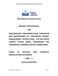
Remove the components of the kit and identify the top, bottom, left, and right parts. On the left and
right parts, locate the "UP" arrow which indicates the top of part. Refer to Figure 1.
Figure 1 - Article 95-3-26
4.
Install the right and left urethane components on the flange of the windshield opening, ensuring the
arrows are pointing up. Refer to Figure 1.
5.
Install the top and bottom urethane components across the top and bottom flange of the windshield
opening. Refer to Figure 1.
6.
Replace weatherstrip and windshield.
OTHER APPLICABLE ARTICLES: NONE
WARRANTY STATUS: Eligible Under Basic Warranty Coverage
LABOR ALLOWANCE
DEALER CODING
OASIS CODES: 102000, 106000
95-3, Publication Date: FEBRUARY 13, 1995
MEDIUM/HEAVY TRUCK:
1987-95 CARGO SERIES, F & B SERIES, L SERIES
ISSUE:
Some trucks may show irregular front axle tire wear and reduced tire life. This can be due to improper total
vehicle alignment, excessive front axle toe-in, excessive bearing adjustment, wrong tires for application, or
other (see appropriate vehicle Service Manual, Page 04-04-8).
ACTION:
Revised front axle assemblies have been designed with symmetrical camber specifications which may reduce
tire wear. Refer to the following procedure for service details.
NOTE:
IT IS THE CUSTOMERS RESPONSIBILITY TO ENSURE TOE-IN AND TOTAL VEHICLE ALIGNMENT
SPECIFICATIONS ARE CORRECT.
SERVICE PROCEDURE
For vehicles exhibiting this concern, check the part number of the axle, This number can be found on the
center of the axle on the web.
Refer to the following chart. If the axle part number falls in the old part number column, the camber needs to
be checked (older axle assemblies may meet the new camber specifications). The revised specification is
3/8°±3/8°.
If the camber does not fall into the specification, the axle assembly needs replacement. Always use new
original equipment U-bolts if replacing axle. Refer to the following chart for correct replacement axle. Refer to
the appropriate vehicle Service Manual for axle replacement procedure and correct torque values.
NOTE:
ADVISE CUSTOMER THAT IF THE AXLE IS REPLACED, THE FRONT AXLE U-BOLTS NEED TO BE
RETORQUED AFTER THE FIRST 1,000 MILES (1 600 km). THEREAFTER, FOLLOW THE
MAINTENANCE SCHEDULE FOR CORRECT RETORQUE INTERVALS.
OTHER APPLICABLE ARTICLES: NONE
WARRANTY STATUS: INFORMATION ONLY
OASIS CODES: 304000
TSB Article 95-4-6 has been superseded by Article 95-8-2.
95-4, Publication Date: FEBRUARY 27, 1995
MEDIUM/HEAVY TRUCK:
1986-93 F & B SERIES, L SERIES
This TSB is being republished in its entirety to include the correct Dealer Coding and Condition Code.
ISSUE:
The Ford New Holland engine may exhibit the need for frequent throttle linkage adjustments because the
throttle linkage/accelerator pedal has excessive free play or the engine lacks power. This may be caused by
the governor lever which may wear and prevent the fuel injection pump from reaching Wide Open Throttle
(WOT). Adjusting the throttle linkage can compensate for this wear, but eventually the wear in the governor
lever will exceed the adjustment capability of the throttle linkage.
ACTION:
Inspect the condition and operation of the Governor Lever Assembly. If the governor lever is excessively loose
or can be rocked side-to-side it should be replaced.
PART FEATURES
Smaller throttle rod attaching bolt hole (on L-Series this will require a smaller throttle ball stud, on
F/B-Series a new throttle rod assembly is used).
It does not have an indexing feature as the previous lever did (the new lever can be installed in any
position on the injection pump shaft).
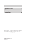
A round spacer with a flat spot in slot/gap of the governor lever (this spacer must be rotated so the
flat spot is aligned with the pump shaft before the new lever can be installed, Figure 1).
Figure 1 - Article 95-4-10
CAUTION:
THE OLD STYLE GOVERNOR LEVER IS DESIGNED SO IT CAN BE INSTALLED ON THE PUMP
SHAFT IN ONLY ONE (1) POSITION. THE NEW LEVER DOES NOT HAVE THIS FEATURE AND IT IS
VERY IMPORTANT THAT THE LEVER IS POSITIONED CORRECTLY TO ENSURE PROPER ENGINE
OPERATION. PLEASE READ THIS ENTIRE PROCEDURE BEFORE ATTEMPTING ANY REPAIRS,
THEN FOLLOW THIS PROCEDURE CAREFULLY.
REPAIR PROCEDURES
L-SERIES:
1.
Remove the throttle spring from the governor lever.
2.
Disconnect the throttle ball stud from the governor lever.
3.
Attach the new ball stud to the throttle rod and screw it on so that it is in the same position as the old
one was.
NOTE:
BEFORE REMOVING THE OLD GOVERNOR LEVER, USE A PERMANENT MARKING PAINT TO
MARK THE LOCATION OF THE OLD GOVERNOR LEVER ON THE PUMP SHAFT.
4.
Mark the injection pump shaft where the lever slot/gap is positioned (this will be used later to properly
position the new lever, Figures 1 and 2).
Figure 2 - Article 95-4-10
5.
Loosen the governor lever pinch bolt and carefully remove the lever from the pump shaft.
6.
Install the new lever with the slot/gap aligned with the paint mark. This will position the new lever in
the same location as the old lever. The spacer located on the pinch bolt in the slot/gap of the new
governor lever may need to be rotated so that it aligns with the pump shaft. This allows the lever to
be installed.
7.
Torque the pinch bolt nut to 90 lb-in (10.2 N-m).
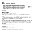
8.
Install the new throttle rod ball stud into the #1 hole on the governor lever (the hole closest to the
pump shaft, Figure 2).
9.
Torque the nut 12-17 lb-ft (16.3-23 N-m).
10.
Connect the throttle return spring to the #2 hole (middle hole of the governor lever, Figure 2).
11.
The #3 hole is not used.
Throttle Adjustment Procedure
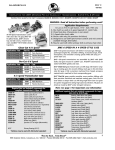
12.
The throttle adjustment procedure (Figure 4) is as follows:
Figure 4 - Article 95-4-10
a.
With the accelerator pedal against the stop bolt, adjust the throttle rod so the fuel injection pump
throttle lever is at full throttle (wide open throttle).
b.
Shorten the throttle rod until approximately 1/16" of break over is achieved at the throttle lever.
c.
Tighten the jam nuts.
d.
Ensure lever has break over when the accelerator pedal is at wide open throttle.
Final Inspection
13.
The final inspection steps are as follows:
a.
Once the new parts have been installed and attaching nuts torqued properly, check the operation
of the accelerator pedal and linkage to ensure it works easily and returns properly.
b.
The pedal must return completely from wide open throttle without any drag or binding.
c.
No surrounding engine compartment components (hoses, wiring, etc.) may contact any moving
part of the accelerator controls.
d.
If the vehicle is equipped with a hand throttle, check the throttle handle for flushness with the dash
panel when engine is at idle. Adjust if required.
NOTE:
THE NEW GOVERNOR LEVER DOES NOT HAVE AN INDEXING FEATURE. THEREFORE, FOR
ANY FUTURE FUEL INJECTION PUMP OR LINKAGE REPAIR THAT REQUIRES REMOVAL OR
REPLACEMENT OF THE GOVERNOR LEVER, IT WILL BE NECESSARY TO NOTE AND/OR
MARK THE LOCATION OF THE LEVER SO THAT IT CAN BE REINSTALLED IN THE CORRECT
POSITION.
F/B-SERIES:
1.
Remove the throttle return spring from the governor lever.
2.
Disconnect the throttle rod from both the governor lever and the accelerator pedal lever.
3.
On this application, the rod must be replaced.
NOTE:
BEFORE REMOVING THE OLD GOVERNOR LEVER, USE A PERMANENT MARKING PAINT TO
MARK THE LOCATION OF THE SLOT/GAP OF THE OLD GOVERNOR LEVER ON THE PUMP
SHAFT.
4.
Mark the injection pump shaft where the lever slot/gap is positioned (this will be used later to properly
position the new lever, Figures 1 and 2).
5.
Loosen the governor lever pinch bolt and carefully remove the lever from the pump shaft.
6.
Install the new lever with the slot/gap aligned with the paint mark. This will position the new lever in
the same location as the old lever. The spacer located on the pinch bolt in the slot/gap of the new
governor lever may need to be rotated so that it aligns with the pump shaft. This allows the lever to
be installed.
7.
Torque the pinch bolt nut to 90 lb-in (10.2 N-m).
8.
Install the new throttle rod ball stud into the #1 hole on the governor lever (the hole closest to the
pump shaft, Figure 2).
9.
Torque the nut 12-17 lb-ft (16.3-23 N-m).
10.
Attach the opposite end of the throttle rod to the accelerator pedal lever.
11.
Torque the attaching nut to 85-115 lb-in (9.6-13 N-m).
12.
Connect the throttle return spring to the #2 hole (middle hole of the governor lever, Figure 2).
13.
The #3 hole is not used.
Throttle Adjustment Procedure
14.
The throttle adjustment procedure (Figure 5) is as follows:
Figure 5 - Article 95-4-10
a.
With the accelerator pedal against the stop bolt, remove the ball stud from the accelerator pedal
blade.
b.
Adjust the rod so the fuel injection pump throttle lever is at full throttle (wide open throttle).
c.
Increase the length of the rod assembly until approximately 1/16" of break over is achieved in the
throttle lever.
d.
Tighten the jam nuts.
Final Inspection
15.
The final inspection steps are as follows:
a.
Once the new parts have been installed and attaching nuts torqued properly, check the operation
of the accelerator pedal and linkage to ensure it works easily and returns properly.
b.
The pedal must return completely from wide open throttle without any drag or binding.
c.
No surrounding engine compartment components (hoses, wiring, etc.) may contact any moving
part of the accelerator controls.
d.
If the vehicle is equipped with a hand throttle, check the throttle handle for flushness with the dash
panel when engine is at idle. Adjust if required.
NOTE:
THE NEW GOVERNOR LEVER DOES NOT HAVE AN INDEXING FEATURE. THEREFORE, FOR
ANY FUTURE FUEL INJECTION PUMP OR LINKAGE REPAIR THAT REQUIRES REMOVAL OR
REPLACEMENT OF THE GOVERNOR LEVER, IT WILL BE NECESSARY TO NOTE AND/OR
MARK THE LOCATION OF THE LEVER SO THAT IT CAN BE REINSTALLED IN THE CORRECT
POSITION.
Figure 3 - Article 95-4-10
SUPERSEDES: 95-2-13
WARRANTY STATUS: Eligible Under Basic Warranty Coverage
LABOR ALLOWANCE
DEALER CODING
OASIS CODES: 610000, 611000, 614000
95-4, Publication Date: FEBRUARY 27, 1995
MEDIUM/HEAVY TRUCK:
1994-95 L SERIES
ISSUE:
On some vehicles, the "Stop Engine", "Engine Warning" or "Engine Fluids" lamp may illuminate incorrectly.
This may be caused by a missing resistor in the low coolant level sensor circuit, wrong connector being
installed on the coolant sensor or corrosion built up on the sensor. Depending on the programming of the
electronic control assembly, the affects could range from illumination of the "Stop Engine" light to decreased
engine power or the engine being shut off.
ACTION:
Determine the cause of the concern by using the following Service Procedure. If necessary, install a Jumper
Wire Assembly (F5HZ-12A690-L) into the low coolant level sensor wiring harness by unplugging the low
coolant level sensor and installing the jumper between the sensor and sensor connector. The jumper wire
assembly has a built-in resistor to reduce the possibility of false illumination of the "Stop Engine" lamp.
SERVICE PROCEDURE CONCERNS
CONCERN #1
The latest generation Detroit Diesel Electronic Engine Control (DDEC-III) requires the low coolant sensor
circuit to have a 560K Ohm resistor for the diagnostic system to function properly. For 1994-1/2 through 1995
L-Series vehicles, this resistor is not present. This could cause a "connector not engaged" fault code. To
resolve this concern, a Service Jumper Wire Assembly (F5HZ-12A690-L) has been released which contains
the resistor. The assembly consists of both mating connectors and can be installed between the low coolant
sensor and the engine wiring harness. All vehicles should have this wiring assembly installed if it is not already
present.
CONCERN #2
The Engine Wiring Harness (-14365-) has two (2) identical electrical connectors at the same location. These
connectors will both engage the low coolant level sensor connector. A visual check should be made if a
"connector not engaged" code is present to ensure the color coding from the engine wiring assembly is GY/Y
and O/BL. If the connector containing the PK and BK wires is connected to the low coolant sensor, remove it
and install the connector which contains the GY/Y and O/BL wires.
CONCERN #3
The polarity of the low coolant level sensor has been found to be incorrect. This will cause an advanced
corrosion build-up condition on the brass fitting which could block the current flow from the brass through the
coolant to the tip. A vehicle with this condition will typically show a low coolant level code from 25,000-50,000
miles (40,200-80,400 km) when the coolant is actually at the proper level.
To correct this concern, perform the following:
1.
Remove enough coolant from the reservoir to remove the low coolant level sensor and remove the
sensor from the reservoir.
2.
With the key in the "On" position and using Rotunda Digital Volt-Ohmmeter (014-00407 or
equivalent), check the polarity of the low coolant level sensor. This system operates on approximately
5 volts DC current. Connect the positive (+) probe to the tip and the negative (-) probe to the brass
connector. A positive (+) reading should appear. If a negative (-) voltage is present, the polarity is
incorrect and needs to be reversed.
3.
If the polarity is incorrect, turn the ignition key to the "Off" position and change the polarity by
removing the wires from the connector shell and reversing their position.
4.
Remove the sensor and examine the edge of the brass which conducts the current for corrosion
build-up (Figure 1). If corrosion is present, remove the corrosion with a small knife and emery cloth
taking caution not to cut or abrade the plastic tip insulator.
Figure 1 - Article 95-4-11
5.
Clean and reinstall the sensor into the reservoir. Ensure Service Jumper (F5HZ-12A690-L) has also
been installed between the engine wiring harness and the low coolant level sensor. Refill coolant as
necessary.
OTHER APPLICABLE ARTICLES: NONE
WARRANTY STATUS: Eligible Under Basic Warranty Coverage
LABOR ALLOWANCE
DEALER CODING
OASIS CODES: 203000, 203200, 206000, 698298
95-5, Publication Date: MARCH 13, 1995
FORD:
1990-93 FESTIVA
1990-94 TEMPO
1990-95 CROWN VICTORIA, ESCORT, MUSTANG, PROBE, TAURUS, THUNDERBIRD
1994-95 ASPIRE
LINCOLN-MERCURY:
1990-92 MARK VII
1990-94 TOPAZ
1990-95 CONTINENTAL, COUGAR, GRAND MARQUIS, SABLE, TOWN CAR, TRACER
1991-94 CAPRI
1993-95 MARK VIII
MERKUR:
1990 SCORPIO
LIGHT TRUCK:
1990 BRONCO II
1990-95 AEROSTAR, BRONCO, ECONOLINE, F SUPER DUTY, F-150-350 SERIES, RANGER
1991-95 EXPLORER
1993-95 VILLAGER
1995 WINDSTAR
MEDIUM/HEAVY TRUCK:
1990-91 C SERIES, CL-CLT-9000 SERIES
1990-95 CARGO SERIES, F & B SERIES, L SERIES
ISSUE:
Current repair procedures do not advise on the addition of refrigerant oil to the A/C system when a minor
repair is made.
ACTION:
Add 0.06 L (2 oz) of the proper type new refrigerant oil to the system, before recharging, when servicing
concerns that do not require major component replacement. Repairs considered minor are: O-ring leaks,
charge port leaks, Pressure Relief Valve (PRV) leaks, compressor shaft seal leaks, hose leaks, etc.
Remember to use polyalkylene glycol (PAG) oil with R-134a systems and mineral oil with R-12 systems.
OTHER APPLICABLE ARTICLES: NONE
WARRANTY STATUS: INFORMATION ONLY
OASIS CODES: 208000, 208999
95-5, Publication Date: MARCH 13, 1995
MEDIUM/HEAVY TRUCK:
1987-94 L SERIES
ISSUE:
The instrument panel cover may crack near the hand throttle on L-Series with the City Delivery Package. This
occurs because this area of the panel lacks sufficient support.
ACTION:
Install a redesigned instrument cluster support bracket to prevent cracking of the instrument panel cover. The
new bracket can be retrofitted on all 1987-94 City Delivery units. If the cover is already cracked, install a new
instrument cluster cover assembly which includes the reinforcing bracket. Refer to the appropriate model year
L-Series Service Manual, Section 13-01, for removal and installation procedures.
OTHER APPLICABLE ARTICLES: NONE
WARRANTY STATUS: Eligible Under Basic Warranty Coverage
LABOR ALLOWANCE
DEALER CODING
OASIS CODES: 107000
TSB Article 95-5-28 has been superseded by Article 97-6-30.
95-5, Publication Date: MARCH 13, 1995
MEDIUM/HEAVY TRUCK:
1991-95 L SERIES
ISSUE:
Air may not blow out of the defrost registers when control lever is in defrost mode on some vehicles. This is
due to a malfunctioning control valve assembly.
ACTION:
Verify vehicle has a malfunctioning valve assembly by positioning the selector lever in the defrost mode. If the
selector does not firmly stay in the defrost position, or little air blows through the defrost register while the fan
is operating, install the new valve assembly (F4HZ-18B679-A or F4HZ-18B679-B, identified by raised letters
F-94) according to the following service details.
REMOVAL
1.
Remove access panel which surrounds the control and remove the two (2) fasteners which secure
the control to the instrument panel.
2.
Carefully pull control assembly back to expose the temperature door cable anchor point. With
needle-nosed pliers or blade-type screwdriver, pinch the blue fitting snap-in tangs and push the fitting
out of the square hole. Hold control firmly with one (1) hand to preclude any type of bending of the
plastic bracket when applying force of any kind.
3.
With the blue fitting free, it will now be possible to disengage the Z-bend at the end of the wire from
the control temperature lever hole. Some articulation of the cable end is required.
4.
Disconnect the tube harness by pressing and holding in the colored release buttons while pulling out
the tubing.
NOTE:
EACH PORT HAS A METAL INSERT OR SLEEVE WHICH ENGAGES THE TUBING INSIDE
DIAMETER. SHOULD THIS INSERT PULL OUT OF THE PORT WITH THE TUBING, MAKE SURE IT
IS RE-ENGAGED INTO THE REPLACEMENT TUBING UPON REASSEMBLY.
5.
Remove the fastener securing the aluminum cover plate.
6.
Remove the two (2) screws securing the electrical mode switch to the bracket.
7.
Remove the two (2) Phillips' head screws securing the spool valve assembly to the bracket.
8.
Lift the spool body gently from the mounting recess by sliding the spool to the lower end of the spool
guide track. Take care not to damage the spool guide fingers.
CAUTION:
DO NOT PULL THE SPOOL OUT OF THE SPOOL BODY. IF THE SPOOL IS REMOVED IT COULD
BECOME CONTAMINATED AND RESULT IN A CONTROL ASSEMBLY FAILURE.
INSTALLATION
1.
Apply a small amount of grease (Lubriplate #30) to the spool guide track.
2.
Gently position the spool slider into the guide track and locate the spool body into its recess.
3.
Reinstall the spool valve assembly and secure with the two (2) Phillips' head screws.
4.
Align the lever slot with the spool slide hole. Position the mode switch so the switch post passes
through the lever slot and slide holes and install the mode switch fasteners.
5.
Reinstall the aluminum cover plate and secure with fasteners.
6.
Reconnect the tube harness to the appropriate color-coded ports. Each tube end has a positive
identification line as a visual check for correct insertion. Lines on all the tubes should not be visible if
properly inserted.
7.
Reinstall the control assembly in the dash panel using the previous steps in reverse order.
OTHER APPLICABLE ARTICLES: NONE
WARRANTY STATUS: Eligible Under Basic Warranty Coverage
LABOR ALLOWANCE
DEALER CODING
OASIS CODES: 208000, 208100, 208200, 208300, 208999
95-5, Publication Date: MARCH 13, 1995
MEDIUM/HEAVY TRUCK:
1987-94 L SERIES
This TSB is being republished in it entirety to update the parts listings.
ISSUE:
The turn signal and hazard warning flasher may become inoperative if the flasher circuit is overloaded.
ACTION:
Install an improved overlay-type harness which provides additional flasher circuit capacity by replacing the
existing 14 gauge circuit in the -14401- wiring assembly with a 10 gauge wire and an improved connector.
This wiring assembly also allows relocation of the flasher from under the instrument panel to a more
accessible location in the circuit breaker panel area. Refer to the following procedure for service details.
1.
Loosely route the new wiring assembly (F4HZ-14A411-A) from the area of the turn signal switch on
the steering column to the area of the circuit panel, Figures 1 and 2.
Figure 1 - Article 95-5-30
Figure 2 - Article 95-5-30
2.
Identify the connector to the turn signal switch which contains six (6) circuits.
a.
Disconnect the connector and remove Circuit 44 (blue) pin from the -14401- connector, by
removing the red locking wedge and releasing the latching tine.
b.
Cut off the pin and tape the remaining wire end, Figure 2.
NOTE:
IF THE CONNECTORS NEED REPLACING, REFER TO THE PARTS LISTINGS FOUND AT THE
END OF THIS ARTICLE FOR THE PROPER PARTS.
3.
Insert the pin/wire from the (F4HZ-14A411-A) wiring assembly into the -14401- connector. Reconnect
the connector halves.
4.
Locate the turn signal flasher. If necessary, follow the wire from the circuit breaker panel back to the
flasher, Figure 2.
a.
Remove the flasher from its present location and relocate it to a position next to the circuit breaker
panel as shown in Figure 2.
b.
Use the same screws to attach the flasher.
5.
6.
Cut the wire presently connected to the flasher stud on the circuit breaker panel.
a.
Tape the cut wire end.
b.
Remove the existing eyelet from the stud and connect the eyelet from the (F4HZ-14A411-A)
wiring assembly.
Using tie straps and/or tape, secure the (F4HZ-14A411-A) wiring assembly to the existing
behind-the-panel harnesses.
OTHER APPLICABLE ARTICLES: NONE
SUPERSEDES: 94-15-23
WARRANTY STATUS: Eligible Under Basic Warranty Coverage
LABOR ALLOWANCE
DEALER CODING
OASIS CODES: 201000, 201200, 203000, 203200
95-5, Publication Date: MARCH 13, 1995
MEDIUM/HEAVY TRUCK:
1980-94 L SERIES
ISSUE:
A wiper arm/blade assembly with improved spring durability has been released for service. The new wiper arm
is the same as the wiper arm that went into production for 1995 except it does not contain the wet arm feature.
The new arms are black. The originals were argent (grayish).
ACTION:
Replace the current arm/blade assembly with F5HZ-17526-B. Two (2) are required per vehicle.
NOTE:
REPLACEMENT BLADE ASSEMBLIES FOR THIS ARM ARE THE 1995 L-SERIES BLADE
F5HZ-17528-A.
OTHER APPLICABLE ARTICLES: NONE
WARRANTY STATUS: INFORMATION ONLY
OASIS CODES: 202000
95-6, Publication Date: MARCH 27, 1995
FORD:
1980 and after CROWN VICTORIA, ESCORT, MUSTANG, THUNDERBIRD
1982-88 EXP
1984-94 TEMPO
1986 and after TAURUS
1988-93 FESTIVA
1989 and after PROBE
1994-95 ASPIRE
1995 CONTOUR
LINCOLN-MERCURY:
1980 and after CONTINENTAL, COUGAR, GRAND MARQUIS, TOWN CAR
1981-87 LYNX
1984-92 MARK VII
1984-94 TOPAZ
1986 and after SABLE
1987-89 TRACER
1991-94 CAPRI
1991 and after TRACER
1993 and after MARK VIII
1995 MYSTIQUE
MERKUR:
1985-89 XR4TI
1988-89 SCORPIO
LIGHT TRUCK:
1980 and after F-150-350 SERIES
1981 and after ECONOLINE
1982 and after BRONCO
1983 and after RANGER
1984-90 BRONCO II
1986 and after AEROSTAR
1988 and after F SUPER DUTY
1991 and after EXPLORER
1993 and after VILLAGER
1995 and after WINDSTAR
MEDIUM/HEAVY TRUCK:
1980-91 C SERIES, CL-CLT-9000 SERIES
1980 and after F & B SERIES, L SERIES
1986 and after CARGO SERIES
ISSUE:
Ferrous metal particles (hot iron dust) are generated by manufacturing facilities, rail shipments, combustion
engines, jet engines, body shops, etc. These particles mechanically/magnetically bond to vehicles' painted
surfaces. Moisture and temperature combine with the particles to create a chemical reaction. The reaction
causes the particles to corrode and enter into the physical paint film.
ACTION:
To remove these particles/contaminants, USE ONLY the following procedure. The procedure must be
performed before any buffing, polishing, color sanding or refinishing is attempted. The materials in this
procedure are alkaline, acidic and neutral. They must be used in the specified order.
CAUTION:
ANY CHANGES TO THIS PROCEDURE WILL CAUSE AN INCOMPLETE OR UNSATISFACTORY
REPAIR AND MAY RESULT IN POSSIBLE DAMAGE TO THE PAINTED SURFACES AND TRIM.
WARNING:
THE TECHNICIAN MUST WEAR PROTECTIVE CLOTHING AND EYE PROTECTION TO PREVENT
SKIN IRRITATION.
CAUTION:
THE USE OF ANY OTHER PRODUCT OR PROCEDURE MAY CAUSE DAMAGE TO ALUMINUM,
FLEXIBLE PAINTED SURFACES OR OTHER PAINTED SURFACES. FOLLOW DIRECTIONS EXACTLY
AND RINSE THOROUGHLY AFTER EACH STEP.
NOTE:
THIS DECONTAMINATION PROCEDURE IS DESIGNED TO REMOVE SURFACE CONTAMINANTS
FROM THE PAINT ON VEHICLES THAT HAVE BEEN CONTAMINATED UP TO 120 DAYS. VEHICLES
WHICH HAVE EXPERIENCED THE CONDITION LONGER THAN THIS PERIOD MAY REQUIRE AN
ADDITIONAL TREATMENT TO REMOVE FERROUS METAL CONTAMINANTS.
IDENTIFICATION
For ease of identifying, the Radio Shack Model 63-851, 30X, lighted, magnifier is recommended.
1.
Ferrous Metal
Light colored vehicles: Small rust orange dots with black in center of stain.
Dark colored vehicles: Small white or silver dots with a "rainbow hue" around the particle. The
surface will also feel rough to the touch.
2.
Industrial Fallout
The surface feels rough to the touch and may exhibit crystalline deposits.
Usually ferrous metal is present, as well as water spots.
3.
Acid Rain
Surface will exhibit irregular discolored spotting.
Dark colored vehicles will show cloudy or greying spots where the acids have started to etch away
the paint.
NOTE:
IN EXTREME CASES ETCHING OF THE SURFACE WILL BE VISIBLE OR FELT.
Figure 1 - Article 95-6-1
DECONTAMINATION
Use Finish Kare Inc. products 1119/883/118SC to decontaminate the paint surface. Follow the manufacturer's
recommended procedures.
NOTE:
FORD DOES NOT RECOMMEND THE USE OF OXALIC ACIDS OR OTHER "FALLOUT REMOVERS".
1.
Rinse off dust and debris with cold water. Be sure to start at the bottom and work up.
2.
Prepare product "1119" by mixing one (1) part "1119" with four (4) parts cold water.
3.
Use clean wash mitt and apply mixture to entire car, starting at the bottom and working up to the
top surface. Keep car wet with the solution for 5 to 10 minutes. Do not allow product to dry on the
car, and do not allow it to streak down the sides. Rewipe with mitt if necessary to avoid
streaks.
4.
Rinse car with cold water.
5.
Dry the flat surfaces of the vehicle hood, roof and deck lid.
6.
Apply product "883" directly to the contaminated surfaces using a clean dry sponge, wash mitt, or soft
truck brush ("883" is ready to use from the bottle, with no mixing involved). Keep the areas wet
with the "883" for 5 to 7 minutes. Do not allow to dry on the car. Wipe down to the body line on the
sides.
7.
Prepare product "118SC" by mixing 1 oz (0.03 L) with 1 gal (3.785 L) of water.
8.
Shampoo the vehicle with "118SC" shampoo mixture using a clean wash mitt and then rinse with cold
water.
NOTE:
DO NOT USE "118SC" MITT WITH "1119" OR "883" SOLUTIONS. USE SEPARATE MITTS AND
ALWAYS KEEP THEM SEPARATE.
9.
Inspect paint surface to see if rust particles have been removed. If rust particles have been on the
vehicle for a long time, it may be necessary to repeat each of the above steps.
NOTE:
THE NEUTRALIZER CONCENTRATE IS A HEAVY DUTY SHAMPOO AND CAN BE USED IN AN
AUTOMATIC CAR WASH SYSTEM.
CORRECTION OF SURFACE FOLLOWING DECONTAMINATION
1.
Visually inspect surface for evidence of removal of ferrous metal particles, crystalline deposits and
water spots. Acid rain discoloring or etching will require either buffing, color sanding or refinishing if
etching is visible.
2.
Use the buffing products from only one (1) manufacturer. Do not intermix products.
3.
Always follow the manufacturer's product sequence. Use appropriate pads with each product as
recommended by the manufacturer.
NOTE:
DO NOT REMOVE MORE THAN 0.3 OF A MIL OF PAINT MATERIAL, OR REPAINTING WILL BE
REQUIRED.
4.
Use a dual action sander (D/A Sander) with a velcro-mount backing plate and appropriate foam pad
for final polishing swirl removal.
5.
Use an alcohol and water mixture (1:4 ratio) to clean buffed areas to verify removal of scratches and
swirls before application of final protective glaze.
NOTE:
FREQUENT WASHING OF VEHICLES IS IMPORTANT. CONTAMINANTS SETTLE ONTO THE
VEHICLE EVERY DAY. USE CLEAN WATER (DEIONIZED, REVERSE OSMOSIS, ETC.) TWICE
WEEKLY TO REMOVE HEAVY DUST, AND PARTICULATES. THE USE OF A NEUTRAL pH CAR
WASH SOAP EVERY TWO (2) WEEKS IS RECOMMENDED TO NEUTRALIZE VEHICLE
CONTAMINATION.
NOTE:
DEALERS SHOULD USE PROGRAM CODE R-23 AND CONDITION CODE C5 AND C6. REFER TO
W & P MANUAL SECTION 5-1, PAGE 3.
OTHER APPLICABLE ARTICLES:
91-18-1
92-6-4
WARRANTY STATUS: Eligible Under The Provisions Of 12 Month/12,000 Mile Basic Warranty Coverage
LABOR ALLOWANCE
DEALER CODING
OASIS CODES: 106000
TSB Article 95-6-20 has been superseded by Article 95-9-12.
TSB Article 95-6-21 has been superseded by Article 95-11-17.
TSB Article 95-7-2 has been superseded by Article 95-23-1.
95-7, Publication Date: APRIL 10, 1995
MEDIUM/HEAVY TRUCK:
1986-95 CARGO SERIES, F & B SERIES, L SERIES
ISSUE:
There have been several requests from the field about the Bosch policies and procedures regarding "Unit
Down" (Vehicle Off Road) (VOR) diesel fuel injection pump repairs on Ford vehicles. This TSB provides
detailed information from Bosch regarding its policies and procedures on VOR repairs.
ACTION:
Refer to the following text for Bosch policies and procedures for VOR repairs.
The Bosch VOR system is an important element in providing prompt customer service. The system is used in
the event specific service parts are not locally available to perform a repair for a "unit down" situation. The
VOR system is provided only upon request. If it is not requested, then either the Bosch regular order (3 to 5
days) or rush order (48 hours) processes are used. To obtain VOR service, a Ford servicing dealer should
communicate to the Bosch Diesel Service Dealer (DSD) the level of urgency or the time the injection pump is
needed for installation on the engine. The DSD will then employ the VOR system if necessary.
BOSCH VOR POLICY AND PROCEDURE
The VOR service is to be used in "unit down" repairs only.
The quantities of parts ordered may be limited to one (1) repair.
The VOR service charges will not be passed on to the Ford Dealer (the Ford dealer will not be
charged any additional amount for the parts or repair of the injection pump when the VOR program is
used).
VOR orders will be shipped the same day if called in by 3:30 PM CST and the part is in the Atlanta
Distribution Center.
In the event the part is not available at the Atlanta Distribution Center, it will be obtained from an
alternative source (DSD inventory, Bosch Germany, Charleston or Brazil). The VOR part will be
shipped as soon as possible, however, in these cases Bosch cannot guarantee 24 hour service.
Ford Customer Service Division has requested and Bosch has implemented a 48 hour service by the Bosch
DSD network. If an injection pump cannot be repaired and returned within two (2) working days, the Ford
dealer can request an exchange pump. The exchange pump will be "Free of Charge" if the pump is still within
the Bosch warranty (exchange pumps are subject to approval by Bosch). If the pump is out of Bosch warranty,
the Ford dealer is to be charged for the exchange pump, but the cost is not to exceed the actual repair cost of
the original pump.
For a fuel injection concern on a FNH or FD engine, the Ford dealer should perform the appropriate diesel
engine diagnostic procedures and repair the system as required. When necessary, the Ford Heavy Truck
Technical Hotline (800-826-4694) can be contacted for assistance in diagnosing and/or repairing hard to
resolve concerns. If the fuel injection pump is removed for service, the Ford dealer should provide the local
Bosch DSD information on the engine symptoms and a time frame when the repaired injection pump is
needed. The Bosch DSD will follow the previously stated policies to ensure the repair is completed promptly.
If, however, there is a delay due to a technical or part availability issue, then the Ford dealer should first
contact the Ford Heavy Truck Hotline for assistance. The Hotline will work with Bosch to help resolve the
concern. If additional assistance is needed, the Ford dealer can work directly with Bosch by contacting Mr.
Ray Chorostecki, Bosch Project Manager at (708) 865-5354 or Mr. Thomas Novak, Bosch National Sales
Manager (708) 865-5260.
OTHER APPLICABLE ARTICLES: NONE
WARRANTY STATUS: INFORMATION ONLY
OASIS CODES: 404000, 601300, 602300, 603300, 617400, 618400
95-7, Publication Date: APRIL 10, 1995
MEDIUM/HEAVY TRUCK:
1992-95 CARGO SERIES, F & B SERIES, L SERIES
ISSUE:
A new service kit for retaining the Diesel Engine plastic Air Cleaner Assembly Covers has been released for
service.
ACTION:
If it becomes necessary to replace the retaining hardware of a plastic air cleaner assembly, use the new Air
Cleaner Cover Hold-down Kit (F4HZ-9C629-A).The air cleaner cover hold-down kit includes the following:
1 (one) Thumb Screw
1 (one) Top Fastener Piece
1 (one) Bottom Fastener Piece
1 (one) Instruction Sheet
OTHER APPLICABLE ARTICLES: NONE
WARRANTY STATUS: INFORMATION ONLY
OASIS CODES: 404000, 499000
95-8, Publication Date: APRIL 24, 1995
FORD:
1986-94 TEMPO
1987-91 CROWN VICTORIA
1987-93 MUSTANG, TAURUS
1989-92 PROBE
1989-93 THUNDERBIRD
1991-94 ESCORT
LINCOLN-MERCURY:
1986-94 TOPAZ
1987-89 TOWN CAR
1987-91 GRAND MARQUIS
1987-93 SABLE
1988-94 CONTINENTAL
1989-93 COUGAR
1991-94 TRACER
1993 MARK VIII
LIGHT TRUCK:
1987-94 BRONCO, F SUPER DUTY, F-150-350 SERIES
MEDIUM/HEAVY TRUCK:
1980-94 L SERIES
1988-95 F SERIES
This TSB is being republished in its entirety to include F-150-350 Series, Bronco, F-Super Duty and
F/B-Series, revise application chart, and to include production dates for L-Series vehicles.
ISSUE:
A revised service windshield wiper motor is now available if the windshield wiper motor requires replacement.
ACTION:
Replace the wiper motor with a revised wiper motor and use a Windshield Wiper Motor Service Kit to complete
the installation. Refer to the Application Chart listed in this article for the proper application. Follow the detailed
instructions included in the service kit.
1.
Inspect the vehicle to see if the new Wiper Motor (-17508-) is already installed. If so, the latest level
of wiring is already installed and the Wiper Motor Wiring Kit (-14A411-) is not required.
2.
Install a new Wiper Motor Assembly. Refer to appropriate Service Manual for installation details.
3.
Use the Wiper Motor Wiring Kit (-14A411-) to complete the installation. The Wiring Kit (-14A411-)
consists of:
One (1) Wiring and Connector Assembly
Seven (7) 5/16" (8mm) Heat Shrink Tubing - 2" (51mm) long
One (1) 37/63 (lead/tin) Solder 0.032" (0.80mm) diameter x 12" (305mm) long
One (1) Adhesive Label
Instruction Sheets
Not included in the kit is the Wiper Motor (-17508-).
OTHER APPLICABLE ARTICLES: NONE
SUPERSEDES: 94-11-20, 95-4-6
WARRANTY STATUS: INFORMATION ONLY
OASIS CODES: 202000
95-8, Publication Date: APRIL 24, 1995
MEDIUM/HEAVY TRUCK:
1993-95 CARGO SERIES, F SERIES, L SERIES
ISSUE:
There may be concerns of reduced operating range of the Two-Way Radio on some vehicles equipped with
Allison World Transmissions (MD and HD Series). This may be due to Radio Frequency Interference (RFI).
The Allison electronic control system complies with all FCC and other guidelines regarding radio frequency
emissions.
ACTION:
Refer to the following guidelines when installing a land mobile radio into a vehicle. These guidelines are
intended to supplement, but not to be used in place of, detailed instructions supplied by the manufacturer of
the land radio being installed. Most concerns of RFI may be eliminated when these installation guidelines are
followed.
GENERAL GUIDELINES
TRANSMITTER LOCATION
1.
The transreceiver for remote radios should be located away from other electronic devices and as
near to the vehicle body side as possible.
2.
One-piece transreceivers should be mounted under the instrument panel where they will not interfere
with the vehicle's controls or passenger movement.
ANTENNA INSTALLATION
Each vehicle model and body style reacts to radio frequency differently. It is suggested that a magnetic mount
antenna be used to check the proposed antenna mounting location for unwanted effects before the antenna is
permanently installed. Antenna location is a major factor in these effects.
ANTENNA CABLE ROUTING
1.
High quality coax (at least 95% shield coverage) should always be used and located away from all
electronic modules.
2.
Cable routing should be done to maintain a great distance between vehicle wiring and the feedline.
ANTENNA TUNING
It is important that the antenna be tuned properly and reflected power be kept to less than 10% (VSWR less
than 2:1).
RADIO WIRING AND CONNECTION LOCATIONS
1.
Both transreceiver power lead connections should be made directly to the battery. For one-piece
transreceivers where the ignition switch is desired, a 12 volt contactor should be located at the
vehicle battery with the coil of the contactor driven through an appropriate in-line fuse from an
available ignition switch circuit which is not powered during cranking. Complete the contactor coil
circuit by returning to battery negative.
2.
Any negative lead from a handset or control unit must return to battery negative. It is preferable that
the positive lead for a handset, or control unit positive and negative leads, be appropriately fused,
separately from the transreceiver positive and negative leads.
WIRE ROUTING
The power and ground connections should be routed through the vehicle as far away as possible from any
electronic modules.
TROUBLESHOOTING
Possible causes of unwanted vehicle RFI include:
a.
Power leads connected to points other than the battery.
b.
Antenna location.
c.
Transreceiver wiring located too close to vehicle electronics.
d.
Poor shielding or poor connections on antenna feed line.
OTHER APPLICABLE ARTICLES: NONE
WARRANTY STATUS: INFORMATION ONLY
OASIS CODES: 203000, 203200, 205000
95-9, Publication Date: MAY 8, 1995
MEDIUM/HEAVY TRUCK:
1988-95 CARGO SERIES, F & B SERIES, L SERIES
This TSB is being republished in its entirety to include L-Series vehicles with back of cab access package.
ISSUE:
The battery box may rattle or crack on some vehicles equipped with outboard frame-mounted battery boxes.
This may be due to the cover latch bracket (spoon) bending downward and reducing the retention of the latch
assembly. The reduced retention may allow the battery box cover to rattle, which on some vehicles may cause
the cover to crack.
ACTION:
Install a new more robust latch bracket (spoon) to the battery box cover in a new location to increase tension.
If the battery box cover is cracked, install a new battery box cover with a new more robust latch bracket
installed on the cover. Refer to the following Service Procedures for details.
SERVICE PROCEDURES
COVER LOOSE, BUT NOT CRACKED
1.
Remove the battery box cover and drill out the two (2) rivets which retain the spoon to the cover.
Remove the spoon and discard.
2.
Install the new Spoon (F5HZ-10A784-A) using the upper battery cover latch hole as the lower hole on
the new latch. This will raise the position of the spoon location on the box cover.
3.
Install the spoon using one (1) 1/4x1/2 Blind Pop Rivet (372820-S36 or equivalent) as described in
Step 2.
4.
Properly align the spoon on the box cover and drill out the new top hole location in the box cover
through the spoon.
5.
Install the Upper Pop Rivet (372820-S36 or equivalent) and reinstall the cover to the battery box.
BATTERY BOX COVER CRACKED
1.
For vehicles with a cracked cover, a new cover assembly may be installed. Refer to the following
Battery Box Application Chart for the proper application.
2.
Remove the old cover assembly and replace it with a new cover assembly. The new cover will include
the new latch in the revised location.
OTHER APPLICABLE ARTICLES: NONE
SUPERSEDES: 95-6-20
WARRANTY STATUS: Eligible Under Basic Warranty Coverage
LABOR ALLOWANCE
DEALER CODING
OASIS CODES: 203000, 305000
95-9, Publication Date: MAY 8, 1995
MEDIUM/HEAVY TRUCK:
1992-94 CARGO SERIES, F & B SERIES, L SERIES
ISSUE:
Some vehicles equipped with FD1060 engine (190 Horsepower) and Allison Automatic Transmission may
exhibit reduced power even after performing TSB «94-3-11». This may be due to the use of a non-wastegated
turbocharger on these engines.
ACTION:
If after performing TSB 94-3-11 a reduced power concern still exists, replace the non-wastegated
turbocharger with a wastegated turbocharger. Refer to the following Service Procedure for details.
SERVICE PROCEDURE
1.
Verify the vehicle complies with the concern description, engine horsepower and model year. Follow
the service procedures outlined in TSB 94-3-11. If the reduced power concern still exists, proceed to
Step 2.
2.
Visually inspect the turbocharger and verify it is wastegated (Item 9 in Figure 1 shows the wastegate
actuator diaphragm). If the turbocharger is not wastegated, replace the turbocharger with a
wastegated Turbocharger (F3HZ-6K682-ARM). Refer to the appropriate Service Manual, Section
03A-04B for removal and installation procedures. The new turbocharger comes with a new mounting
gasket, studs and nuts. Additionally, an Oil Return Line Gasket (F3HZ-6N652-B) is required.
Figure 1 - Article 95-9-13
OTHER APPLICABLE ARTICLES:
94-3-11
WARRANTY STATUS: Eligible Under Basic Warranty Coverage
LABOR ALLOWANCE
DEALER CODING
OASIS CODES: 614000, 614500
95-9, Publication Date: MAY 8, 1995
MEDIUM/HEAVY TRUCK:
1994-95 L SERIES
ISSUE:
The main drive belt may experience early wear and/or the drive belt may roll off the fan hub on some vehicles.
This may be due to an interference between the fan hub mounting surface and an engine noise shield
mounting bolt causing the fan clutch pulley to not be parallel to the front of the engine.
ACTION:
Replace the main drive belt and remove a bolt which is causing the interference between the fan hub
mounting surface and the engine noise shield. Refer to the following Service Procedure for details.
SERVICE PROCEDURE
1.
Loosen the generator mounting fasteners, and loosen the adjusting nuts enough to remove the
V-belts from the generator. Refer to the Service Manual, Section 14-02C.
2.
Remove the fan clutch assembly. Refer to Service Manual, Section 03C-05. Remove and discard the
14-rib polygroove drive belt.
3.
Locate the engine noise shield mounting bolt which is causing the interference. Refer to Figure 1.
Remove and discard the bolt.
Figure 1 - Article 95-9-14
4.
Replace the main drive belt. Refer to the Application Chart for the correct belt. Reinstall the fan clutch
and install the mounting bolts finger tight. Adjust the clutch to obtain 1245-1557 Newtons (N)
(280-350 Pounds Force (lb)) on the main drive belt. Torque the mounting bolts to 102-142 N-m
(75-105 lb-ft).
5.
Reinstall the generator drive belts, adjust the generator to achieve 400-490 Newtons (N) (90-110
Pounds Force (lb)) on the belts. Tighten the jam nuts on the adjusting link. Torque the generator
mounting nut to 102-142 N-m (75-105 lb-ft).
6.
Start the engine and allow it to run for 10 minutes. Stop the engine and recheck the drive belt tension.
If the belt tension has dropped below 934 Newtons (N) (210 Pounds Force (lb)), readjust the fan
clutch to obtain 1112-1156 Newtons (N) (250-260 Pounds Force (lb)).
OTHER APPLICABLE ARTICLES: NONE
WARRANTY STATUS: Eligible Under Basic Warranty Coverage
LABOR ALLOWANCE
DEALER CODING
OASIS CODES: 206000, 303000, 402000, 497000
95-10, Publication Date: MAY 22, 1995
MEDIUM/HEAVY TRUCK:
1995 F & B SERIES, L SERIES
ISSUE:
A Hydromax brake reservoir mounting bracket separation concern may occur on some vehicles. The
separation occurs where the reservoir mounting brackets are welded to the reservoir. Seepage of automatic
transmission fluid may appear at the separated area, resulting in low fluid level in the brake power assist
system. A low fluid level would activate the electric brake assist motor, which actuates the "BRK ELEC MTR"
(brake electric motor) warning lamp and a buzzer would sound. These symptoms are caused by varying
vibration between subject models, resulting in early reservoir bracket separation on some and no bracket
separation on others.
ACTION:
Install a tubular support bracket which attaches to the engine cylinder head and hydraulic reservoir brackets.
Refer to the following Service Procedure for details.
SERVICE PROCEDURE
1.
Remove the Hydromax Brake Reservoir (Item 1, Figures 1 and 2). Discard the reservoir, four (4) nuts
and two (2) of the bolts. Install a new Hydromax Brake Reservoir (F5HZ-2N148-A, F/B-Series and
F3HZ-2N148-A, LN-Series) using two (2) of the existing bolts on the right side with two (2) new
torque prevailing 5/16-18 Grade 5 nuts (33770-S2) (Item 5, Figures 1 and 2). Torque nuts from 16-23
N-m (12-17 lb-ft).
Figure 1 - Article 95-10-13
Figure 2 - Article 95-10-13
2.
For F/B-Series, remove the bolt (Item 4, Figure 1) from the engine cylinder head charge air tubing
casting, which retains the -9A627- air cleaner bracket. Discard bolt. LN-Series vehicles do not have a
bolt in this location.
3.
Install the Tubular Support Bracket (Item 3, Figures 1 and 2) (F5HZ-2K017-BB, F/B-Series and
F5HZ-2K017-AB, LN-Series) to the reservoir and reservoir mounting bracket. Use two (2) new
5/16x18x1.00" Grade 5 flanged bolts (376256-S) (Item 2, Figures 1 and 2) and two (2) new torque
prevailing 5/16x18 Grade 5 flanged nuts (33770-S2) (Item 5, Figures 1 and 2). Torque nuts from
16-23 N-m (12-17 lb-ft).
4.
For F/B-Series and LN-Series:
5.
a.
F/B-Series: Install a M10x1.5x25mm P/C 9.8 hex head bolt (N605545-S100) (Item 4, Figure 1) to
secure the tubular bracket over the air cleaner support bracket to the charged air cooling casting.
Torque bolt from 41-62 N-m (30-46 lb-ft).
b.
LN-Series: Install a M10x1.5x20mm P/C 9.8 hex head bolt (N605544-S2) (Item 4, Figure 2)
through the tubular support bracket directly to the charged air tubing casting. Torque bolt from
41-62 N-m (30-46 lb-ft).
Fill and bleed the Hydromax system to the proper level using Motorcraft Mercon or equivalent. Refer
to the appropriate Service Manual, Section 06-05B, for proper fill and bleeding procedure.
OTHER APPLICABLE ARTICLES: NONE
WARRANTY STATUS: Eligible Under Basic Warranty Coverage
LABOR ALLOWANCE
DEALER CODING
OASIS CODES: 301000
95-10, Publication Date: MAY 22, 1995
MEDIUM/HEAVY TRUCK:
1986-89 CARGO SERIES
ISSUE:
Diagnostic and repair service information concerns for air over hydraulic brake systems may occur for some
vehicles. The following diagnostic procedures are intended to supplement the information published in the
1986-89 Cargo Truck Service Manual.
ACTION:
Please refer to the following Sections for service details.
CONTENTS
SECTION I
INSPECTION PROCEDURE
SECTION II
PRESSURE DIFFERENTIAL VALVE ASSEMBLY DIAGNOSTIC AND REPLACEMENT
SECTION III
DIFFERENTIAL VALVE FUNCTIONAL CHECK
SECTION I
INSPECTION PROCEDURE
HYDRAULIC LEAK TEST
FLUID LEVEL CHECK
HYDRAULIC LEAK TEST
1.
With the parking brake applied, visually inspect all hydraulic lines, connections and hoses for
evidence of leaks. Replace leaking parts as necessary. Specifically, inspect the area of the pressure
differential valve noting any leakage of fluid from the valve or the switch. Inspect the frame rail for
missing paint due to valve leakage. If leakage is evident, go to SECTION II (valve replacement). This
valve is located inside the right frame rail, close to the alternator.
2.
Check the brake piston seals or rear drum brake wheel cylinders for evidence of leaks. Replace as
needed.
3.
Inspect all fittings and connections for leaks. Tighten fittings and replace O-rings as needed.
FLUID LEVEL CHECK
CAUTION:
FAILURE TO OBSERVE ALL PRECAUTIONS PREVENTING CONTAMINATION OF THE BRAKE
SYSTEM WILL RESULT IN DETERIORATION OF RUBBER PARTS, LEADING TO REDUCED
BRAKE PERFORMANCE.
4.
With hood open, before removing filler caps, wipe off the outside of fill cap with a clean, dry cloth to
prevent contaminants from getting into reservoir when filler caps are removed.
NOTE:
THERE ARE TWO (2) MASTER CYLINDERS ON THESE VEHICLES.
5.
Remove the filler caps from the master cylinder.
6.
Check and fill if necessary, to the level of the bottom of the rings as indicated on the master cylinder
reservoir(s). Use new DOT 3 brake fluid from a sealed container.
CAUTION:
NEVER USE BRAKE FLUID WHICH HAS BEEN DRAINED FROM THE HYDRAULIC SYSTEM OR
THAT HAS BEEN STORED IN AN OPEN CONTAINER.
7.
Replace the master cylinder filler caps.
SECTION II
PRESSURE DIFFERENTIAL VALVE ASSEMBLY DIAGNOSTIC AND REPLACEMENT
BRAKE WARNING LAMP SYSTEM TEST
NOTE:
WHEN BOTH BRAKE SYSTEMS ARE FUNCTIONING NORMALLY, EQUAL PRESSURE ON BOTH
SIDES OF THE PRESSURE DIFFERENTIAL VALVE WILL KEEP THE VALVE CENTERED DURING
BRAKE PEDAL APPLICATION. THE BRAKE WARNING LAMP WILL ILLUMINATE ONLY WHEN THE
IGNITION KEY IS IN THE START POSITION AND WILL GO OUT AFTER APPROXIMATELY 1/2
SECOND.
1.
Turn the ignition switch to ACC or ON. The red brake warning lamp should be off. If the lamp remains
on, go to Step 7.
2.
Turn the ignition switch to start. The warning lamp should illuminate for approximately 1/2 second. If
the red brake warning lamp does not illuminate, check the lamp bulb and replace if necessary, then
recheck. If lamp illuminates and flashes for approximately 1/2 second and then goes out, the warning
system is functioning properly, go to SECTION III. If not, continue with next step.
3.
If the brake warning lamp still does not illuminate after the bulb has been replaced, simulate pressure
not being equal in both brake systems by disconnecting the red secondary delivery line on the foot
valve (Figure 2, Item 1). Apply and release the brakes. This should cause the piston in the valve to
shuttle over and make contact with the switch, causing the lamp to come on.
Figure 2 - Article 95-10-14
4.
If the brake warning lamp does not illuminate when pressure is not equal in both brake systems, the
warning switch may be inoperative or the switch-to-lamp wiring may have an open circuit.
5.
Remove the switch, ground the metal collar on the switch and push in center pin. If lamp illuminates,
switch is good. If the warning lamp does not illuminate, replace the switch. If replacement of the
switch does not cause the warning lamp to illuminate, check the wiring. If it still fails to illuminate,
replace the Differential Pressure Valve Assembly (E6HZ-2K493-A). Refer to Step 6 for installation,
then proceed to SECTION III.
NOTE:
IF THE VALVE IS NOT REPLACED IN STEP 5, RE-CENTER THE VALVE BY USING THE
PROCEDURE IN SECTION III, STEP 3.
6.
Following are removal and installation procedures for Differential Pressure Valve Assembly.
Removal (Refer to Figure 1)
Figure 1 - Article 95-10-14
a. Disconnect electrical connector at pressure differential switch.
b. Clean dirt from around hydraulic line fittings. Allow hydraulic fluid to drain into a suitable container.
c. Remove clip which secures hydraulic line (routed from T-fitting) at pressure differential valve
assembly. When positioning this, or any, hydraulic line aside, take care not to bend or crimp.
d. Remove nut and washer from retaining attaching bolt. Withdraw both bolts and remove pressure
differential assembly.
Installation (Refer to Figure 1)
a. Position pressure differential assembly on frame side rail and install forward bolt.
b. Install remaining attaching bolt, securing hydraulic line and clip at pressure differential assembly.
c. Install line fittings to pressure differential assembly.
d. Tighten pressure differential assembly attaching bolts to 17-23 N-m (12-17 lb-ft).
e. Tighten hydraulic line fittings to 17-23 N-m (12-17 lb-ft).
f. Connect electrical connector at pressure differential switch.
g. Fill reservoirs with Ford Heavy Duty Brake Fluid C6AZ-19542-AA or -BA (ESA-M6C25-A) or an
equivalent DOT 3 fluid to fill mark and bleed system.
7.
If the brake warning lamp remains on after Step 1, there may be a shorted or broken switch,
grounded switch wires, or an non-centered pressure differential valve. Remove the switch from the
valve. If the lamp remains on, check the wiring for a ground. If the lamp goes out, check the switch
and replace if necessary. Reinstall the switch in the valve body. If the lamp comes on again, the valve
is not centered.
8.
Re-center the valve by disconnecting the red supply line and very slowly applying the brake. If the
lamp goes out, reconnect the supply line and go to SECTION III, Step 3. If the lamp stays on,
reconnect the red supply line and disconnect the green line. Again, slowly apply the brake. If the lamp
goes out, reconnect the supply line and go to SECTION III, Step 3.
SECTION III
DIFFERENTIAL VALVE FUNCTIONAL CHECK (After Replacement of Valve)
1.
Again, simulate unequal pressure by disconnecting the secondary delivery line on the foot valve
(Figure 2, Item 1). With ignition on, apply the brakes. This should cause the piston to shuttle over and
allow contact between the piston and switch. This contact should cause the lamp to illuminate.
Illumination of lamp indicates the differential pressure valve system is functioning properly.
2.
Reconnect the red delivery line (Figure 2, Item 1) and loosen the green primary delivery line (Figure
2, Item 2). Very slowly apply the brake until the lamp goes out. This action forces the piston to shuttle
in the opposite direction, centering it in the valve body. If too much pressure is applied, the piston will
shuttle too far and the lamp will remain on. The procedure to re-center the piston will have to be
reversed. Reconnect green line (Figure 2, Item 2) and tighten.
3.
Last check is with the ignition in the ACC or ON position; the brake warning lamp should be off. In the
start position, the warning lamp should be on for approximately 1/2 second. With the ignition switch in
the ON position, step on the brake pedal. The warning lamp should remain off. If the warning lamp
comes on again, the brakes may be out of adjustment or a leak exists that was not identified in
SECTION I. Once this condition is corrected, the valve will have to be re-centered.
4.
After this procedure is done and valve is functioning properly, the General Inspection Procedures
should be done to check the brake system functionality, refer to Cargo Service Manual, Section 12 Brakes, Air/Hydraulic Brakes.
OTHER APPLICABLE ARTICLES: NONE
WARRANTY STATUS: INFORMATION ONLY
OASIS CODES: 301000
95-10, Publication Date: MAY 22, 1995
MEDIUM/HEAVY TRUCK:
1985-91 C SERIES, CL-9000
1985-94 F & B SERIES, L SERIES
1986-94 CARGO SERIES
ISSUE:
Conversion kits are available to convert systems using R-12 refrigerant to R-134a refrigerant.
ACTION:
If it becomes necessary to convert A/C systems using R-12 refrigerant to R-134a refrigerant, refer to the
following for details.
RPO A/C R-12 TO R-134a CONVERSION
It is important to note the following when converting R-12 systems to R-134a systems.
This process will permanently convert a factory installed R-12 A/C system to an R-134a system.
Once converted, the system cannot be converted back to an R-12 system.
It is recommended that all R-12 systems be repaired using R-12 whenever possible.
If R-12 is not available, the system must be converted to an R-134a system.
R-12 "substitutes" are NOT recommended or approved. Conversion to R-134a is the only acceptable
method of updating an R-12 system.
PROCEDURE
An RPO A/C system conversion requires two (2) parts:
Order an R-12 to R-134a conversion kit from the following Application Chart. One (1) kit will be
needed for each vehicle converted. A complete instruction sheet is included with each conversion kit.
A new accumulator or receiver/drier must also be ordered. Replace the current accumulator with a
new accumulator of the same part number.
L-Series vehicles built prior to the 1991-1/2 model year used a receiver/drier instead of an
accumulator. Replace the current receiver/drier with a new receiver/drier chosen from the following
chart.
NOTE:
R-134a REFRIGERANT AND CHARGE EQUIPMENT WILL BE REQUIRED.
For L-Series vehicles built prior to the 1991-1/2 model year (December 1991), replace the receiver/drier with
an R-134a compatible receiver/drier (see chart below). All other vehicles have R-134a compatible
components.
SLEEPER HEATER A/C UNITS
Sleeper evaporator cores are located beneath the bunk in the luggage compartment area. All R-12
evaporator cores are "Box" shaped units and all R-134a evaporator cores are "Wedge" shaped units.
R-12 "Box" evaporators can be made R-134a compatible by changing the Thermal Expansion Valve
(TXV) IN ADDITION TO ALL CHANGES RECOMMENDED TO THE BASE RPO SYSTEM.
The old R-12 TXV (Red Dot part number RD-4157-0) should be replaced with a 1-1/2 ton R-134a
TXV (part number RD-5-7125-0) available directly from Red Dot.
Red Dot Corporation
P.O. Box 58270
Seattle, Washington 98138
Telephone: (206) 575-3840
IN CAB KYSOR KA700 SIDEKICK A/C UNITS
Existing R-12 KA700 units can be made R-134a compatible by replacing the Thermal Expansion
Valve (TXV). The KA700 R-12 TXV (Kysor part number 404098) should be replaced with a Kysor
R-134a TXV (part number 404255) available directly from Kysor.
Kysor/Westran
602 East Blackhawk Drive
Byron, Illinois 61010-0921
Telephone: (815) 234-2811
OTHER APPLICABLE ARTICLES:
93-5-16
WARRANTY STATUS: INFORMATION ONLY
OASIS CODES: 208000, 208200
TSB Article 95-10-17 has been superseded by Article 95-13-9.
95-10, Publication Date: MAY 22, 1995
MEDIUM/HEAVY TRUCK:
1992-95 CARGO SERIES, F & B SERIES, L SERIES
ISSUE:
There may be some concerns over the correct part application regarding FD1060 Diesel engine crankshaft
dampers. This article provides the correct part applications and identification.
ACTION:
If service is required for the FD1060 engine, install the correct part per the Application Chart. Refer to the
following for correct applications.
PRODUCTION AND SERVICE PART APPLICATION
The FD1060 engine can use either a rubber or viscous crankshaft damper, depending on the type of
transmission that is used.
All vehicles equipped with the Allison AT-545 automatic transmission will use a rubber-type damper
(F3HZ-6312-B). The AT-545 transmission design allows it to dampen the engine vibration/noise similar to
what a viscous damper would, therefore allowing the use of the rubber crankshaft damper.
All other transmissions, manual and automatic use a viscous damper (F3HZ-6312-G). During the early build
period of the FD1060 engine, two (2) different styles of crankshaft dampers and adapters were used.
However, all service replacement viscous crankshaft dampers and adapters will be the latest level
(F3HZ-6312-G damper, F3HZ-6A329-A adapter).
Some early production FD1060 engines that were to be equipped with the viscous crankshaft damper, were
instead built with a rubber crankshaft damper. If the engine serial number (the serial number is located on the
engine data plate, which is attached to the front gear housing) is between 44726807 and 44731926, and the
vehicle is equipped with a transmission other than the AT-545, then it probably has the incorrect rubber
damper. Use of the rubber damper in applications that require a viscous damper can increase the noise level
of the engine. If a particular engine is within the serial number range and there is a concern with the engine
noise level, the original crankshaft damper should be replaced with the viscous damper.
PART IDENTIFICATION
The rubber damper assembly is one-piece. The viscous damper assembly consists of three (3) separate
pieces: damper, adapter and drive belt pulley (Figure 1).
Figure 1 - Article 95-10-18
POWER TAKE OFF (PTO) USAGE
Both the rubber and viscous dampers can be used with a crankshaft-mounted PTO adapter. Refer to the
Application Chart for the correct part number and application.
VISCOUS DAMPER RETROFIT
Use the following parts to retrofit a viscous damper in place of a rubber damper:
Viscous Damper (F3HZ-6312-G)
Adapter (F3HZ-6A329-A)
Drive Belt Pulley (F3HZ-6312-A)
Bolt Kit - longer capscrews (Cummins part number 3924584 or Ford part number 3924584-CF1 hex
flange head capscrews)
Refer to Section 03A-01 of the appropriate Powertrain/Drivetrain Service Manual for the damper installation
procedures and attaching bolt torque specifications.
OTHER APPLICABLE ARTICLES:
94-8-24
WARRANTY STATUS: INFORMATION ONLY
OASIS CODES: 490000, 499000
95-11, Publication Date: JUNE 5, 1995
MEDIUM/HEAVY TRUCK:
1990-94 L SERIES
This TSB article is being republished in its entirety to revise the affected serial numbers and vehicles.
ISSUE:
The transmission countershaft bearing end clearance may not be within specification on some vehicles. This
could result in an early countershaft bearing concern. The affected transmission was installed on Ford
vehicles as a DSO option. Direct drive and 13-speed transmissions are not involved.
ACTION:
Call the Rockwell Customer Service Center Hotline, 800-535-5560 (USA and Canada), for information
regarding this program. Rockwell Transmission will repair the failed transmissions with factory remanufactured
transmissions under warranty. For vehicles domiciled in Australia, contact Rockwell International located in
Sunshine, Victoria, Australia.
OTHER APPLICABLE ARTICLES: NONE
SUPERSEDES: 95-6-21
WARRANTY STATUS: INFORMATION ONLY
OASIS CODES: 505000, 597997
95-11, Publication Date: JUNE 5, 1995
MEDIUM/HEAVY TRUCK:
1993-95 CARGO SERIES, F & B SERIES, L SERIES
ISSUE:
The Fuel Shutdown Solenoid wiring harness may rub against the Fuel Injector Lines and create a short circuit.
This may be caused by the convoluted tubing not fully enclosing the Fuel Shutdown Solenoid wiring harness
allowing it to rub on the fuel lines.
ACTION:
Install a stand-off bracket and secure the wiring to the bracket to move the wiring away from the fuel lines.
Refer to the Instruction Sheet (I.S. 6672) included in the kit and the following for service details.
1.
Install the stand-off bracket using the M12 bolt and washer as shown in Figure 1. Torque the bolt to
44-70 lb-ft (60-95 N-m).
Figure 1 - Article 95-11-15
2.
Install the retaining clip around the Fuel Shutdown Solenoid wire and secure to the Stand-off Bracket
as shown in Figure 1. Ensure that the wiring has adequate clearance from the injector lines. Torque
the 5/16 bolt to 12-17 lb-ft (16-23 N-m).
The Stand-off Bracket Kit (F5HZ-8K157-CA) includes the following:
One (1) Bracket
Two (2) Bolts
One (1) Washer
One (1) Nut with Washer
One (1) Instruction Sheet (I.S. 6672)
OTHER APPLICABLE ARTICLES: NONE
WARRANTY STATUS: Eligible Under Basic Warranty Coverage And Emissions Warranty Coverage
LABOR ALLOWANCE
DEALER CODING
OASIS CODES: 203000, 404000
95-11, Publication Date: JUNE 5, 1995
MEDIUM/HEAVY TRUCK:
1970-90 L SERIES
ISSUE:
A revised heater blower switch with a retrofit wiring connector has been developed.
ACTION:
Splice the wiring assembly into the existing harness. This will allow for the installation of the revised heater
blower switch. Refer to the following procedure for service details.
SERVICE PROCEDURE
1.
Remove the climate control assembly, referring to the appropriate Service Manual. Remove the
heater blower switch and disconnect the electrical connector.
2.
Cut the blower switch wiring approximately 4-6" (102-152mm) from the end of the connector.
3.
Strip all cut wiring 0.3" (7.6mm). Match the color coding of the new assembly to the existing wiring
from the main harness.
NOTE:
ON OLDER VEHICLES, A CIRCUIT NUMBER AND COLOR CHANGE IS APPARENT ON ONE (1)
WIRE. THESE VEHICLES WILL NOT HAVE CIRCUIT #57 (BLACK) TO THE BLOWER SWITCH.
INSTEAD, THEY WILL HAVE CIRCUIT #399 (BROWN). IF ENCOUNTERED, SPLICE CIRCUIT #399
(BROWN) OF THE EXISTING HARNESS INTO CIRCUIT #57 (BLACK) OF THE NEW WIRING
HARNESS.
4.
Insert the corresponding wires into the wiring assembly (F5HZ-14A411-A). Crimp all connectors.
Apply heat to all of the dual wall butt splice until the insulation shrinks and adhesive flows from each
end.
5.
Remove the blower motor switch, and replace with new switch (FOHZ-19986-A), connect the switch
to the wiring assembly.
6.
Reinstall the climate control assembly.
OTHER APPLICABLE ARTICLES: NONE
WARRANTY STATUS: Eligible Under Basic Warranty Coverage
LABOR ALLOWANCE
DEALER CODING
OASIS CODES: 203000, 208000
95-11, Publication Date: JUNE 5, 1995
MEDIUM/HEAVY TRUCK:
1990-94 L SERIES
This TSB article is being republished in its entirety to revise the affected serial numbers and vehicles.
ISSUE:
The transmission countershaft bearing end clearance may not be within specification on some vehicles. This
could result in an early countershaft bearing concern. The affected transmission was installed on Ford
vehicles as a DSO option. Direct drive and 13-speed transmissions are not involved.
ACTION:
Call the Rockwell Customer Service Center Hotline, 800-535-5560 (USA and Canada), for information
regarding this program. Rockwell Transmission will repair the failed transmissions with factory remanufactured
transmissions under warranty. For vehicles domiciled in Australia, contact Rockwell International located in
Sunshine, Victoria, Australia.
OTHER APPLICABLE ARTICLES: NONE
SUPERSEDES: 95-6-21
WARRANTY STATUS: INFORMATION ONLY
OASIS CODES: 505000, 597997
95-12, Publication Date: JUNE 19, 1995
MEDIUM/HEAVY TRUCK:
1989-95 LL-9000, LTL-9000
ISSUE:
The hood may not fully open on some vehicles. This is due to insufficient length of the hood check cables.
ACTION:
Install new Hood Check Cables as outlined in the appropriate Service Manual, Section 01-02. The cables were
lengthened by 127mm (5") allowing more forward travel when the hood is tilted. This allows the hood to travel
beyond its center of gravity to fully open past its pivot point on vehicles with or without a bright chrome grille
surround.
OTHER APPLICABLE ARTICLES: NONE
WARRANTY STATUS: Eligible Under Basic Warranty Coverage
LABOR ALLOWANCE
OASIS CODES: 108000
95-12, Publication Date: JUNE 19, 1995
MEDIUM/HEAVY TRUCK:
1988-94 L SERIES
ISSUE:
TSB 92-12-22 provided new one-piece spiral grooved bushings and TSB 93-18-17 provided bronze thrust
washers to reduce front spring "popping" noises. The bronze thrust washers were replaced with thicker,
hardened steel washers in TSB 94-18-14. Further analysis has revealed the need for additional tools for
reaming the spring eyes and spot facing suspension connection points. The procedures for using the new
tools are incorporated into these instructions. The new procedure allows the springs to remain fastened to the
front axle. Also, the need for the broach (D94T-3110-A or equivalent) has been eliminated.
ACTION:
Install the new thicker, hardened steel thrust washers to improve the fit-up of the front springs, and lubricate
the bushings with Ford-approved grease. The new bushings were added in production during the 1993 model
year launch. The new washers are a service part only to correct the bushing/spring bracket tolerance issue.
Refer to the following procedure for service details.
THE ROTUNDA SPRING SHACKLE REPAIR KIT (139-00100) MUST BE USED TO PERFORM THIS TSB
ARTICLE. THE KIT INCLUDES THE FOLLOWING:
2.25" Diameter Spot Facing Cutter (Piloted)
T-Wrench with 4" Tube
8" Extension Tube
Bit Cleaning Brush
Hex Driver
Tool Case
1.25" Diameter Reamer
1.00" Diameter Wire Brush
1.25" Diameter Wire Brush
Three (3) Replacement Carbide Bits (One Replacement Set)
NOTE:
REFER TO THE 1994 L-SERIES SERVICE MANUAL, SECTION 04-01A, FOR ILLUSTRATIONS AND
FASTENER TORQUE VALUES.
INSPECTION PROCEDURE
1.
Apply the parking brake and chock the rear wheels.
a.
Raise the front of the vehicle evenly until the front wheels are off the ground.
b.
Position jack stands under each frame rail and lower the vehicle onto the stands. This removes
the weight from both sides of the front suspension.
NOTE:
PERFORM THE FOLLOWING AT BOTH THE FRONT AND REAR SPRING EYES AND AT THE
SHACKLE BRACKETS ON BOTH SIDES OF THE VEHICLE (SIX (6) TOTAL BUSHING
LOCATIONS), ONE SIDE AT A TIME.
2.
Place a floor jack under the front axle and raise enough to relieve the weight off the springs.
3.
Remove the front rear shackle bracket clinch bolts and nuts (right and left hand side). Remove the
shackle pins and shackle brackets and lower the floor jack. Support the axle enough to allow access
in the shackle area.
4.
Inspect the bushings to determine if the bushings are the spiral groove type (it may be necessary to
remove some grease to identify the grooves). If the bushing inner surface is smooth, replace the
bushing with the new spiral groove type bushing (Steps 4-7 in this article).
5.
Inspect the following for wear:
Shackle brackets and bushings
Shackles
Spring eye bushings
Front hanger brackets
The shackles, shackle brackets and front spring hanger must be inspected for grooves where parts
could come into contact.
NOTE:
IF THE FORD-APPROVED LUBRICANT WAS NOT USED ON THE VEHICLE, THE REMAINING
GREASE MUST BE REMOVED AND THEN THE APPROVED LUBE (SEE FIGURE 1) MUST BE
USED TO PREVENT PREMATURE BREAKDOWN OF THE LUBE.
Figure 1 - Article 95-12-11
CAUTION:
MIXING INCOMPATIBLE LUBRICANTS WILL CAUSE EITHER SOLIDIFICATION OR
LIQUIFICATION OF THE LUBE MIXTURE.
NOTE:
USE ONLY FORD-APPROVED LUBE (XG-1-C PREFERRED). OTHER LUBES HAVE NOT
PERFORMED ACCEPTABLY IN THIS APPLICATION. THE RECOMMENDED LUBE SERVICE
INTERVAL IS EVERY 6000 MILES (9660 KM).
SERVICE PROCEDURE
If the bushings are worn or found to be the old design, install new Spiral Groove Bushings (F2HZ-5348-A) in
all three (3) connections according to the following procedure. Use the special service tools listed below.
139-00100 - Rotunda Spring Shackle Repair Kit
D94T-3110-B - Non-Expanding Arbor
D94T-3110-C - Expanding Arbor
1.
Using the non-expanding arbor tool (D94T-3110-B) and a large C-clamp, press out the old shackle
bracket bushing and press in the new shackle bracket bushing.
2.
Using the expanding arbor tool (D94T-3110-C) and a large C-clamp, press the old bushings out of
the spring eyes.
3.
Clean the spring eye using the 1.25" brush included in the Rotunda Spring Shackle Repair Kit
(139-00100).
4.
Ream the spring eyes by rotating clockwise with the 1.25" reaming tool included in the Rotunda
Spring Shackle Repair Kit (139-00100). The reamer must pass completely through the spring eye to
be properly sized.
NOTE:
THE REAMER MUST ALWAYS APPROACH THE SUSPENSION CONNECTIONS AS SHOWN IN
FIGURE 2 TO PREVENT DAMAGING THE REAMER.
Figure 2 - Article 95-12-11
5.
Press the new bushings (F2HZ-5348-A) in with C-clamps and non-expanding arbor (D94T-3110-B).
6.
Clean the shackle and the front spring hanger pin bores by using the 1.00" diameter wire brush
included in the Rotunda Spring Shackle Repair Kit (139-00100). Remove all grease from the shackle
bracket area that contacts the spring.
7.
Using the spot face tool and T-wrench included in the Rotunda Spring Shackle Repair Kit
(139-00100), spot face the shackle and shackle bracket as required to remove any raised or grooved
material. This will normally be on the thrust side of the bracket, which is the location where the steel
thrust washers will be placed during assembly. Clean the cutting edges of the spot face tool
frequently during use with the brush included for cutting performance and bit life.
NOTE:
TURN THE SPOT FACING TOOL BY HAND ONLY. THE USE OF A POWER SOURCE WILL
DAMAGE THE TOOL BODY AND CUTTING EDGES. THIS TOOL IS DESIGNED TO REMOVE
RAISED AND/OR GROOVED MATERIAL ONLY, NOT TO MACHINE THE ENTIRE SURFACE AREA.
8.
Reassemble the rear shackles and brackets with the new shackle pins (E5HZ-5780-B for a 6.7" pin
and E5HZ-5780-A for a 6.1" pin). Prior to fully seating the shackle pins, shift/pry the spring away from
the spot faced surface and install steel thrust washers (F4HZ-5A879-A (0.030") and F4HZ-5A879-B
(0.040")) between the spring and shackle bracket. Select the thrust washers to obtain the closest fit
possible (it may be necessary to spot face again if a slight adjustment is needed to obtain the tightest
possible fit).
9.
Install all retaining nuts and bolts and torque to specifications using the appropriate Service Manual
specifications.
10.
Remove the front spring pin, perform Steps 6-15 on the front spring hanger bracket and spring.
11.
Lubricate all front suspension pivot points using the Ford approved lubricant (XG-1-C).
12.
Remove the jack stands and lower the vehicle.
OTHER APPLICABLE ARTICLES: NONE
SUPERSEDES: 92-12-22, 94-18-14
WARRANTY STATUS: Eligible Under Basic Warranty Coverage
LABOR ALLOWANCE
DEALER CODING
OASIS CODES: 203200, 303000, 304000, 702000, 702100
TSB Article 95-12-12 has been superseded by Article 96-6-12.
95-13, Publication Date: JULY 3, 1995
MEDIUM/HEAVY TRUCK:
1991-95 L SERIES
ISSUE:
The tilt and telescoping steering column may have free play.
ACTION:
To improve this condition, a kit has been made available for service which contains an Instruction Sheet and
plug.
OTHER APPLICABLE ARTICLES: NONE
WARRANTY STATUS: Eligible Under Basic Warranty Coverage
LABOR ALLOWANCE
OASIS CODES: 303000
95-13, Publication Date: JULY 3, 1995
MEDIUM/HEAVY TRUCK:
1986-93 CARGO SERIES
This TSB is being republished in its entirety to correct the vehicles affected and the model years.
ISSUE:
The A/C belt may roll off the pulley on some vehicles equipped with dealer installed A/C and 7.8L FNH engine.
This may be due to instability of the idler bracket assembly.
ACTION:
Replace the single pulley idler with a new dual pulley idler. The dual pulley idler should improve the stability of
the long A/C drive belt. Refer to the following Service Procedure for details.
SERVICE PROCEDURE
1.
Remove the A/C drive belt.
2.
Verify the harmonic balancer pulley has no more than 0.020" runout using a dial indicator. If runout
exceeds 0.020", replace the pulley and recheck runout.
NOTE:
CHECK COMPRESSOR PULLEY ALIGNMENT WITH HARMONIC BALANCER PULLEY BEFORE
REPLACING IDLER/BRACKET ASSEMBLY. MAKE ADJUSTMENTS AS NECESSARY.
3.
Remove the single pulley idler assembly.
4.
Install the new dual pulley idler assembly (E8HZ-19K603-A).
5.
Reinstall the A/C drive belt (replace if worn).
6.
Run the engine for 10-15 minutes to allow the belt to stretch.
7.
Readjust the drive belt.
OTHER APPLICABLE ARTICLES: NONE
SUPERSEDES: 95-10-17
WARRANTY STATUS: Eligible Under Basic Warranty Coverage
LABOR ALLOWANCE
DEALER CODING
OASIS CODES: 208000, 208200
95-14, Publication Date: JULY 17, 1995
MEDIUM/HEAVY TRUCK:
1990-94 L SERIES
ISSUE:
Objectionable noise or vibration may be transmitted through the shift tower/lever into the cab on some
L-Series vehicles. This is caused by the lack of isolation on the shift lever.
ACTION:
Install an isolated shift tower/lever to the current transmission. Refer to the following Service Procedure for
details.
SERVICE PROCEDURE
1.
Remove the shift knob, including the air lines for the shift selector making note of their location.
2.
Remove the cab floor transmission access panel, including the shift boot. Remove panel and boot
over the shift lever.
3.
Remove the shift tower/lever assembly from the top of the transmission. Discard the gasket and
retain the bolts for reuse.
4.
Install the new shift lever assembly (refer to chart in this article for correct part application) and
gasket (3208-N-1080). Torque bolts from 34-47 N-m (25-35 lb-ft).
5.
Install the floor transmission access panel removed in Step 2.
6.
Install the shift knob removed in Step 1, and reinstall the air lines to the shift knob.
OTHER APPLICABLE ARTICLES: NONE
WARRANTY STATUS: Eligible Under Basic Warranty Coverage
LABOR ALLOWANCE
DEALER CODING
OASIS CODES: 505000, 505200, 702000, 703000
95-14, Publication Date: JULY 17, 1995
MEDIUM/HEAVY TRUCK:
1993-95 F SERIES, L SERIES
ISSUE:
Clutch rod assemblies with improved bushing-to-housing containment have been released for service. The
improved clutch rod should reduce the possibility of the bushing becoming attached to the ball portion of the
swivel, thus spinning the bushing in the housing.
ACTION:
If service to the clutch rod assembly becomes necessary, replace the clutch rod assembly with an improved
clutch rod assembly. Refer to the following Application Chart for the proper Service Part numbers. Refer to
Section 08-02 of the appropriate Service Manual for replacement procedures.
OTHER APPLICABLE ARTICLES: NONE
WARRANTY STATUS: INFORMATION ONLY
OASIS CODES: 505200, 506000
95-15, Publication Date: JULY 31, 1995
MEDIUM/HEAVY TRUCK:
1986-93 CARGO SERIES
1988-93 F & B SERIES
This TSB is being republished in its entirety to correct part number usage for the pitman arm in Figure 1 and
to arrange text to flow with figures.
ISSUE:
Production of the Bendix steering gear has been discontinued. Sufficient Service parts are available to support
the field with Bendix gears for several years. However, a customer may want the option to replace the Bendix
steering gear with the current production Ross steering gear.
ACTION:
As required, replace the Bendix steering gear with a Ross steering gear. Refer to the following procedure and
its attachments for part requirements and service details.
REPLACEMENT OF C500N STEERING GEAR WITH ROSS TAS65 STEERING GEARS
APPLICATION: F-SERIES WITH 10000/12000 LB (ROSS TAS65) FRONT AXLE
PROCEDURE: Bendix Gear Removal
1.
Thoroughly clean off all outside dirt, especially around fittings.
CAUTION:
DO NOT STEAM CLEAN OR HIGH-PRESSURE WASH HYDRAULIC STEERING ASSEMBLIES OR
FORCE/ABUSE CLOSELY FITTED PARTS. DAMAGE WILL RESULT.
2.
Disconnect the power steering pressure and return lines at the gear and drain fluid.
3.
Disconnect the drag link from the pitman arm.
4.
Remove the pitman arm pitch bolt and nut (save for reuse). Optional: Remove the pitman arm from
the sector shaft using Pitman Arm Puller (T64P-3590-F).
5.
Remove intermediate shaft U-joint nut and bolt and disconnect it from the steering gear input shaft.
6.
Disconnect steering gear mounting hardware and remove the gear from the truck's side rail.
7.
Remove power steering pump per Service Manual, Section 13 (pre-1993 model years) instructions.
NOTE:
REFER TO FIGURE 1 FOR PART USAGE INFORMATION.
Figure 1 - Article 95-15-15
Ross Gear Installation
NOTE:
PLEASE REFER TO 1993 OR NEWER FORD SERVICE MANUAL, SECTION 11-02, FOR DETAILS
CONCERNING FINAL GEAR ADJUSTMENTS OF THE SECTOR SHAFT, PITMAN ARM AND POPPET
VALVES TO SUPPLEMENT THE GENERAL INSTALLATION OUTLINE GIVEN BELOW.
1.
Install the power steering pump per appropriate model year Service Manual. NOTE THAT THIS NEW
HIGHER PRESSURE PUMP IS REQUIRED BECAUSE THE ROSS TAS65 GEAR USES A HIGHER
PRESSURE SYSTEM (150 BAR VS. 140 BAR FOR BENDIX GEAR).
2.
Place the gear on the side rail and install the nuts and bolts. Torque bolts to 299-406 N-m (220-300
lb-ft).
3.
Install intermediate shaft U-joint onto the steering gear input shaft. Torque bolts to 68-95 N-m (50-70
lb-ft).
4.
Place new pitman arm on the steering gear sector shaft and align the arm's notch with the notch on
the end of the sector shaft. Use a chisel to spread the pitman arm and slide it onto the sector shaft.
WARNING:
DO NOT USE A HAMMER TO FORCE THE PITMAN ARM ONTO THE SECTOR SHAFT. THIS
COULD DAMAGE SECTOR SHAFT BEARINGS AND CAUSE LOSS OF GEAR PRELOAD.
5.
Install pitman arm pitch bolt and nut. Torque nut to 299-406 N-m (220-300 lb-ft).
6.
Attach pitman arm to drag link, torque nut to 150-204 N-m (111-151 lb-ft). Insert cotter pin.
7.
Install 45 degree elbow on the gear pressure port and align the elbow so that its centerline is parallel
to the truck's side rail. Attach the pressure line and return line to the gear.
NOTE:
TAKE CARE NOT TO CRIMP THE LINES. REFER TO FIGURE 4.
Figure 4 - Article 95-15-15
8.
Fill the reservoir with Motorcraft (MERCON Multi-Purpose Auto-Transmission Fluid, XT-2-QDX
(E4AZ-19582-B) or equivalent).
9.
To check system for leaks, remove air from the system and check power assist through range of
wheel articulation. Start engine, rotate wheels from wheel stop to stop.
DO NOT HOLD THE WHEELS AGAINST THE STOPS FOR LONGER THAN 5 SECONDS.
If power assist is significantly reduced before reaching the stop bolts, check stop bolts for proper setting. If
the bolt setting is correct, or the setting has been corrected, and stop bolts are not contacted, refer to the
Truck Service Manual, Steering Diagnosis and Testing Section.
REPLACEMENT OF C300N STEERING GEAR WITH ROSS TAS40/55 STEERING GEARS
APPLICATION: F/B-SERIES WITH: 6000-7000 LB FRONT AXLE, BENDIX C300N TO ROSS TAS40;
8000-9000 LB FRONT AXLE, BENDIX C300N TO ROSS TAS55
PROCEDURE:
1.
Thoroughly clean off all outside dirt, especially around fittings.
CAUTION:
DO NOT STEAM CLEAN OR HIGH-PRESSURE WASH HYDRAULIC STEERING ASSEMBLIES OR
FORCE/ABUSE CLOSELY FITTED PARTS. DAMAGE WILL RESULT.
2.
Disconnect the power steering pressure and return lines at the gear.
3.
Disconnect the drag link from the pitman arm.
4.
Remove the pitman arm pitch bolt and nut. Remove the pitman arm from the sector shaft using
Pitman Arm Puller (T64P-3590-F).
5.
Remove intermediate shaft U-joint nut and bolt and disconnect it from the steering gear input shaft.
6.
Disconnect steering gear mounting hardware and remove the gear from the truck's side rail.
NOTE:
THE 5/8" MOUNTING BOLTS MUST BE REPLACED BY 3/4" SIZE BOLTS. TO REMOVE THE TWO
(2) FORWARD 5/8" BOLTS, CUT THE BOLTS IN HALF. THE SIDE RAIL HOLES MUST THEN BE
ENLARGED TO TAKE THE 3/4" BOLTS (RECOMMENDED HOLE SIZE IS 0.812/0.786" DIAMETER).
7.
Disconnect hydraulic lines and remove power steering pump.
NOTE:
REMOVE THE DRIVE GEAR FROM THE PUMP ON DIESEL ENGINES AND REMOVE THE PULLEY
AND RESERVOIR FROM THE PUMPS ON GAS ENGINES AND SAVE. THESE PARTS WILL BE
REUSED ON THE REPLACEMENT PUMPS.
NOTE:
REFER TO FIGURE 2 FOR PART USAGE INFORMATION.
Figure 2 - Article 95-15-15
Ross Gear Installation
NOTE:
PLEASE REFER TO 1993 OR NEWER FORD SERVICE MANUAL, SECTION 11-02A, FOR DETAILS
CONCERNING FINAL GEAR ADJUSTMENTS OF THE SECTOR SHAFT, PITMAN ARM AND POPPET
VALVES TO SUPPLEMENT THE GENERAL INSTALLATION OUTLINE GIVEN BELOW.
1.
Place the gear on the side rail and install the nuts and bolts. Torque bolts to 407-433 N-m (300-320
lb-ft).
NOTE:
INSTALL THE 3/4" BOLTS WITH THE BOLT HEADS OUTBOARD AND NUTS INBOARD.
2.
Install intermediate shaft U-joint onto the steering gear input shaft. Torque bolts to 68-95 N-m (50-70
lb-ft).
3.
Place the pitman arm on the steering gear sector shaft and align the arm's notch with the notch on
the end of the sector shaft. Use a chisel to spread the pitman arm and slide it onto the sector shaft.
4.
Install arm pitch bolt and nut. Torque nut to 407-433 N-m (300-320 lb-ft).
5.
Attach pitman arm to drag link. Torque to 103-142 N-m (76-105 lb-ft). Insert cotter pin.
6.
Install 45 degree elbow on gear pressure port and align the elbow so that its centerline is parallel to
the truck's side rail. Attach pressure and return lines to the gear. TAKE CARE NOT TO CRIMP THE
LINES. Refer to Figure 4 for elbow orientation.
7.
Fill the reservoir with Motorcraft (MERCON Multi-Purpose Auto-Transmission Fluid, XT-2-QDX
(E4AZ-19582-B) or equivalent).
8.
To check system for leaks, remove air from the system and check power assist through range of
wheel articulation. Start engine, rotate wheels from wheel stop to stop.
DO NOT HOLD THE WHEELS AGAINST THE STOPS FOR LONGER THAN 5 SECONDS.
If there is a significant reduction in power assist before reaching the stop bolts, check stop bolts for proper
setting. If the bolt setting is correct, or the setting has been corrected, and stop bolts still are not contacted,
refer to the Truck Service Manual, Steering Diagnosis and Testing Section.
REPLACEMENT OF C500 STEERING GEAR WITH ROSS TAS65 STEERING GEARS
APPLICATION: CF-SERIES WITH 12000 LB (ROSS TAS65) FRONT AXLE
PROCEDURE: Bendix Gear Removal
1.
Thoroughly clean off all outside dirt, especially around fittings.
CAUTION:
DO NOT STEAM CLEAN OR HIGH-PRESSURE WASH HYDRAULIC STEERING ASSEMBLIES OR
FORCE/ABUSE CLOSELY FITTED PARTS. DAMAGE WILL RESULT.
2.
Disconnect the power steering pressure and return lines at the gear and drain fluid.
3.
Disconnect the drag link from the pitman arm.
4.
Removal of the pitman arm is optional. To remove the pitman arm from the sector shaft use Pitman
Arm Puller (T64P-3590-F).
5.
Remove intermediate shaft U-joint nut and bolt and disconnect it from the steering gear input shaft.
6.
Disconnect steering gear mounting hardware and remove the gear from the truck's side rail.
7.
Remove power steering pump per Service Manual, Section 13 (pre-1993 model years). instructions.
8.
Install Pressure Relief Kit (F3HZ-3A561-C) per the appropriate Service Manual.
NOTE:
REFER TO FIGURE 3 FOR PART USAGE INFORMATION.
Figure 3 - Article 95-15-15
Ross Gear Installation
1.
Install the power steering pump with the revised relief valve per the appropriate Service Manual.
NOTE THAT A NEW HIGHER PRESSURE PUMP IS REQUIRED BECAUSE THE ROSS TAS65
GEAR USES A HIGHER PRESSURE SYSTEM (150 BAR VS. 140 BAR FOR BENDIX GEAR).
2.
Place the gear on the side rail and install the nuts and bolts. Torque bolts to 299-406 N-m (220-300
lb-ft).
3.
Install intermediate shaft U-joint onto the steering gear input shaft. Torque bolts to 68-95 N-m (50-70
lb-ft).
4.
Place the pitman arm on the steering gear sector shaft and align the arm's notch with the notch on
the end of the sector shaft. Use a chisel to spread the pitman arm to slide onto the sector shaft.
WARNING:
DO NOT USE A HAMMER TO FORCE THE PITMAN ARM ONTO THE SECTOR SHAFT. THIS
COULD DAMAGE SECTOR SHAFT BEARINGS AND CAUSE LOSS OF GEAR PRELOAD.
5.
Install arm pitch bolt and nut. Torque nut to 299-406 N-m (220-300 lb-ft).
6.
Attach pitman arm to drag link. Torque to 150-204 N-m (111-151 lb-ft). Insert cotter pin.
7.
Install the pressure and return lines to the gear and pump. TAKE CARE NOT TO CRIMP THE
LINES.
8.
Fill the reservoir with Motorcraft (MERCON Multi-Purpose Auto-Transmission Fluid, XT-2-QDX
(E4AZ-19582-B) or equivalent).
9.
To check system for leaks, remove air from the system and check power assist through range of
wheel articulation. Start engine, rotate wheels from wheel stop to stop.
DO NOT HOLD THE WHEELS AGAINST THE STOPS FOR LONGER THAN 5 SECONDS.
If there is a significant increase in steering effort before reaching the stop bolts, check them for proper
setting. If the bolt setting is correct, or the setting has been corrected, and stop bolts are not contacted,
refer to the Truck Service Manual, Steering Diagnosis and Testing Section.
Refer to the Ford Service Labor Times Manual for applicable labor operations.
OTHER APPLICABLE ARTICLES: NONE
SUPERSEDES: 94-25-8
WARRANTY STATUS: INFORMATION ONLY
OASIS CODES: 303000
95-15, Publication Date: JULY 31, 1995
MEDIUM/HEAVY TRUCK:
1989-95 FT-800, FT-8000, FT-900, L SERIES
ISSUE:
Standard rear axle brake chambers extend beyond the profile of the rear tires. Dealer Special Order (DSO)
offers the availability of an asphalt spreader option to re-index the rear axle brake chambers away from the
asphalt spreading device or other aftermarket apparatus. Vehicles not ordered with this option and used in this
vocation may experience an interference concern with the brake chambers and the asphalt spreader or other
aftermarket equipment.
ACTION:
If interference is a concern and the vehicle was not DSO equipped with the asphalt spreader option, re-index
the rear brake chambers. Refer to the following Service Procedure for details.
SERVICE PROCEDURE
1.
Chock the front wheels to prevent unintended movement and remove the rear wheels, axle shafts,
hubs and brake drums. Refer to the appropriate Service Manual, Sections 05-02A and 04-04 for
details.
2.
Remove the foundation brakes of the tandem rear axle, including the brake spider, camshaft bracket,
etc. Refer to the appropriate Service Manual, Section 06-08D for details. Check the condition of the
slack adjusters and brake chambers. Retain for re-use if they are in an acceptable condition.
3.
Refer to the Application Chart listed in this article to install the correct brake assembly and refer to the
correct Figure for brake assembly indexing.
Figure 1 - Article 95-15-16
Figure 2 - Article 95-15-16
Figure 3 - Article 95-15-16
Figure 4 - Article 95-15-16
4.
Install the correct brake assembly using the correct Figure. Install the twelve (12) 9/16-18x1.88 Grade
8 bolts and twenty four (24) flatwashers (Grade 8) that were removed in a previous step. Install
twelve (12) new 9/16-18 Grade 8 torque prevailing nuts (55720-S2) and torque to 135-165 lb-ft
(183-224 N-m).
5.
Install a new wheel seal into the hub and reinstall the hub/drum on the axle. For Rockwell Axles,
adjust the wheel bearings as outlined in the appropriate Service Manual, Section 04-02B. For Eaton
Axles, refer to the procedures found in this article.
6.
Install the axle shaft, gasket, dowels, washers and nuts and torque the axle shaft nuts to the
specifications listed in Section 04-02B of the appropriate Service Manual.
7.
Install the brake chambers and slack adjusters and manually adjust the slack adjusters for initial
brake adjustment.
8.
Reinstall the wheels and torque to the proper specifications.
The following Service Procedures apply to all Eaton drive axle wheel and assemblies and has been taken
from Eaton Bulletin #AXIB-9405.This bulletin details the following service and assembly procedures:
Wheel end seal installation
Wheel bearing adjustment for the three-piece tang-type, three-piece dowel-type and four-piece
tang/dowel-type lockwasher wheel nut systems
Wheel end lubrication
WARNING:
NEVER WORK UNDER A VEHICLE SUPPORTED BY ONLY A JACK. ALWAYS SUPPORT THE
VEHICLE WITH STANDS. BLOCK THE WHEELS AND ENSURE VEHICLE WILL NOT ROLL
BEFORE RELEASING THE BRAKES.
WHEEL END SEAL
NOTE:
WHEEL END SEALS CAN BE EASILY DAMAGED DURING HANDLING. LEAVE THE SEAL IN THE
PACKAGE UNTIL INSTALLATION TO PREVENT DAMAGE OR CONTAMINATION.
1.
Remove:
a.
The outer bearing and wheel.
b.
The inner bearing.
c.
The oil seal or grease retainer and discard.
d.
The old wear sleeve (two-piece design only) with a ball peen hammer and discard.
CAUTION:
DO NOT CUT THROUGH THE OLD WEAR SLEEVE. DAMAGE TO THE HOUSING MAY
RESULT.
2.
Inspect:
a.
The spindle journal and hub for scratches and burrs. Recondition with an emery cloth as required.
NOTE:
DEEP GOUGES CAN BE REPAIRED BY FILLING GOUGE WITH HARDENING GASKET CEMENT
AND THEN SMOOTHING WITH AN EMERY CLOTH.
3.
Clean:
a.
The hub cavity and bearing bores before disassembly. Be sure to remove contaminants from all
recesses and corners.
b.
The bearing thoroughly with solvent and examine for damage. Replace damaged or worn
bearings.
4.
Before installation, lubricate the following with the same lubricant used in the axle sump:
a.
The inner bearing.
b.
The wheel seal following the directions provided by the seal supplier.
NOTE:
ALWAYS USE THE SEAL INSTALLATION TOOL SPECIFIED BY THE SEAL MANUFACTURER.
USING AN IMPROPER TOOL CAN DISTORT OR DAMAGE THE SEAL AND CAUSE
PREMATURE SEAL FAILURE.
WHEEL BEARING ADJUSTMENT
1.
Identify the wheel nut system being installed. Three (3) systems are available:
a.
Three-piece dowel-type wheel nut system, Figure 5.
Figure 5 - Article 95-15-16
b.
Three-piece tang-type wheel nut system, Figures 6 and 8.
Figure 6 - Article 95-15-16
Figure 8 - Article 95-15-16
c.
Four-piece tang/dowel-type wheel nut system, Figures 7 and 9.
Figure 7 - Article 95-15-16
Figure 9 - Article 95-15-16
WARNING:
DO NOT MIX SPINDLE NUTS AND LOCKWASHERS FROM DIFFERENT SYSTEMS. MIXING
SPINDLE NUTS AND LOCKWASHERS MAY CAUSE WHEEL SEPARATION.
NOTE:
THE LOCKWASHER FOR A FOUR-PIECE TANG/DOWEL-TYPE WHEEL NUT SYSTEM IS
THINNER THAN THE LOCKWASHER FOR A THREE-PIECE TANG-TYPE WHEEL NUT SYSTEM
AND IS NOT DESIGNED TO BEAR AGAINST THE INNER NUT.
2.
Inspect the spindle and nut threads for corrosion and clean thoroughly or replace as required.
NOTE:
PROPER ASSEMBLY AND ADJUSTMENT IS NOT POSSIBLE IF THE SPINDLE NUT OR THREADS
ARE CORRODED.
a.
3.
Inspect the tang-type washer (if used). Replace the washer if the tangs are broken, cracked or
damaged.
Install the hub and drum on the spindle with care to prevent damage or distortion to the wheel seal.
CAUTION:
A WHEEL DOLLY IS RECOMMENDED DURING INSTALLATION TO ENSURE WHEEL SEAL IS
NOT DAMAGED BY THE WEIGHT OF THE HUB AND DRUM. NEVER SUPPORT THE HUB ON THE
SPINDLE WITH JUST THE INNER BEARING AND SEAL. THIS CAN CAUSE DAMAGE TO THE
SEAL AND CAUSE PREMATURE FAILURE.
a.
4.
Completely fill the hub cavity between the inner and outer bearing races with the same lubricant
used in the axle sump.
Before installation, lubricate the outer bearing with the same lubricant used in the axle sump.
NOTE:
LUBRICATE ONLY WITH CLEAN AXLE LUBRICANT OF THE SAME TYPE USED IN THE AXLE
SUMP. DO NOT PACK BEARINGS WITH GREASE BEFORE INSTALLATION. GREASE WILL
PREVENT THE PROPER CIRCULATION OF THE AXLE LUBRICANT AND MAY CAUSE WHEEL
SEAL FAILURE.
5.
Install:
a.
The outer bearing on the spindle.
b.
The inner nut on the spindle.
c.
Tighten the inner nut to 271 N-m (200 lb-ft) while rotating the wheel hub.
CAUTION:
NEVER USE AN IMPACT WRENCH TO ADJUST WHEEL BEARINGS. A TORQUE WRENCH IS
REQUIRED TO ASSURE THE NUTS ARE PROPERLY TIGHTENED.
6.
Back off the inner nut one (1) full turn. Rotate the wheel hub.
7.
Retighten the inner nut to 68 N-m (50 lb-ft) while rotating the wheel hub.
8.
Back off the inner nut exactly 1/4 turn.
NOTE:
THIS ADJUSTMENT PROCEDURE ALLOWS THE WHEEL TO ROTATE FREELY WITH 0.001-0.005"
(0.025-0.127mm) END PLAY.
9.
Install the correct lockwasher for the wheel nut system being used.
THREE-PIECE TANG-TYPE LOCKWASHER SYSTEM
1.
Install the tang-type lockwasher on the spindle.
NOTE:
NEVER TIGHTEN THE INNER NUT FOR ALIGNMENT. THIS CAN PRELOAD THE BEARING AND
CAUSE PREMATURE FAILURE.
2.
Install the outer nut on the spindle and tighten to 339 N-m (250 lb-ft).
3.
Verify end play. Refer to the End Play Verification Procedure in this article.
4.
After verifying end play, secure wheel nuts by bending one (1) of the locking washer tangs over the
outer wheel nut and another tang over the inner wheel nut as shown in Figure 8.
5.
Install:
a.
New gasket at axle shaft flange.
b.
Axle shaft.
c.
Axle flange and tighten to specified torque.
6.
Lubricate axle wheel ends. Refer to the Wheel End Lubrication Procedure in this article.
THREE-PIECE DOWEL-TYPE LOCKWASHER SYSTEM
1.
Install the dowel-type lockwasher on the spindle.
NOTE:
IF THE DOWEL PIN AND WASHER ARE NOT ALIGNED, REMOVE THE WASHER, TURN IT OVER
AND REINSTALL. IF REQUIRED, LOOSEN THE INNER NUT JUST ENOUGH FOR ALIGNMENT.
NEVER TIGHTEN THE INNER NUT FOR ALIGNMENT. THIS CAN PRELOAD THE BEARING AND
CAUSE PREMATURE FAILURE.
2.
Install the outer nut on the spindle and tighten to 475 N-m (350 lb-ft).
3.
Verify end play. Refer to the End Play Verification Procedure in this article.
4.
Install:
5.
a.
New gasket at axle shaft flange.
b.
Axle shaft.
c.
Axle flange and tighten to specified torque.
Lubricate axle wheel ends. Refer to the Wheel End Lubrication Procedure in this article.
FOUR-PIECE TANG/DOWEL-TYPE LOCKWASHER SYSTEM
1.
Install the dowel-type washer on the spindle.
NOTE:
IF THE DOWEL PIN AND WASHER ARE NOT ALIGNED, REMOVE THE WASHER, TURN IT OVER
AND REINSTALL. IF REQUIRED, LOOSEN THE INNER NUT JUST ENOUGH FOR ALIGNMENT.
NEVER TIGHTEN THE INNER NUT FOR ALIGNMENT. THIS CAN PRELOAD THE BEARING AND
CAUSE PREMATURE FAILURE.
2.
Install the tang-type lockwasher on the spindle.
3.
Install the outer nut on the spindle and tighten to 339 N-m (250 lb-ft).
4.
Verify end play. Refer to the End Play Verification Procedure in this article.
5.
After verifying end play, secure the outer nut by bending two (2) opposing (180 degrees apart) tangs
of the locking washer over the outer nut as shown in Figure 9.
6.
Install:
7.
a.
New gasket at axle shaft flange.
b.
Axle shaft.
c.
Axle flange and tighten to specified torque.
Lubricate axle wheel ends. Refer to the Wheel End Lubrication Procedure in this article.
END PLAY VERIFICATION PROCEDURE
1.
Verify that end play meets specification using a dial indicator. An indicator with 0.001" (0.025mm)
resolution is required. Wheel end play is free movement of the tire and wheel assembly along the
spindle axis.
2.
Attach a dial indicator with its magnetic base to the hub or brake drum as shown in Figure 10.
Figure 10 - Article 95-15-16
3.
Adjust the dial indicator so that its plunger or pointer is against the end of the spindle with its line of
action approximately parallel to the axis of the spindle.
4.
Grasp the wheel assembly at the 3 o'clock and 9 o'clock positions. Push the wheel assembly in and
out while oscillating it to seat the bearings. Read bearing end play as the total indicator movement.
5.
If end play is not in specification, readjustment is required. Refer to the End Play Readjustment
Procedure in this article.
END PLAY READJUSTMENT PROCEDURE
EXCESSIVE END PLAY
If the end play is greater than 0.005" (0.127mm), remove the outer nut and pull the lockwasher away from the
inner nut but not off the spindle. Tighten the inner nut to the next alignment hole of the dowel-type washer (if
used). Reassemble the washer and retorque the outer nut. Verify end play with a dial indicator.
INSUFFICIENT END PLAY
If the end play is not present, remove the outer nut and pull the lockwasher away from the inner nut but not off
the spindle. Loosen the inner nut to the next alignment hole of the dowel-type washer (if used). Reassemble
the washer and retorque the outer nut. Verify end play with a dial indicator.
FINE TUNING END PLAY
If, after performing the readjustment procedures, end play is still not within the 0.001-0.005" (0.025-0.127mm)
range, disassemble and inspect the components. If parts are found to be defective, replace the defective
parts, reassemble and repeat wheel bearing adjustment procedure. Verify end play with a dial indicator.
WHEEL END LUBRICATION
NOTE:
BEFORE OPERATING THE AXLE, THE WHEEL HUB CAVITIES AND BEARINGS MUST BE
LUBRICATED TO PREVENT FAILURE.
When wheel ends are serviced, follow Eaton's wheel end lubricating procedure before operating the axle.
Eaton axles may be equipped with either of the following two (2) wheel end designs:
Wheel ends with an oil fill hole, Figure 11
Figure 11 - Article 95-15-16
Wheel ends without an oil fill hole, Figure 11
WHEEL ENDS WITH AN OIL FILL HOLE
1.
Rotate the wheel end hub until the oil fill hole is up.
2.
Remove the oil fill plug.
3.
Pour 1/2 pint of axle sump lubricant into each hub through the wheel end fill hole.
4.
Install oil fill plug and tighten to the specified torque.
WHEEL ENDS WITHOUT AN OIL FILL HOLE
1.
With the axle level and wheels assembled, add lubricant through filler hole located in axle housing
cover until fluid is level with the bottom of the filler hole.
2.
Raise the left side of the axle 6" (152mm) or more. Hold that position for 1 minute, Figure 12.
Figure 12 - Article 95-15-16
3.
Lower the left side back to its original position.
4.
Raise the right side of the axle 6" (152mm) or more. Hold that position for 1 minute, Figure 12.
5.
Lower the right side back to its original position.
6.
With the axle level, add lubricant through the axle housing cover filler hole until the fluid is level with
the bottom of the filler hole.
NOTE:
AXLES WITHOUT WHEEL END FILL HOLES WILL REQUIRE APPROXIMATELY 2.5 ADDITIONAL
PINTS OF LUBRICANT TO BRING THE LEVEL EVEN WITH THE BOTTOM OF THE FILLER HOLE.
OTHER APPLICABLE ARTICLES: NONE
WARRANTY STATUS: INFORMATION ONLY
OASIS CODES: 301000, 302000
95-15, Publication Date: JULY 31, 1995
MEDIUM/HEAVY TRUCK:
1992-95 CARGO SERIES, F SERIES, L SERIES
ISSUE:
There may be an oil leak from the front cover area on some vehicles with FD1460 engines. Typical repair
procedures for replacing gaskets may be ineffective. A front engine cover design revision has occurred and
was put into production in September 1994. A list of service changes to resolve this condition are as follows:
New service steel-edged moulded rubber gasket
New formed-in-place front cover gasket
New "sunrise" gear cover
Improved capscrews with a property class of 10.9
Improved air compressor mounting
ACTION:
If service is required, replace the front cover and gasket with the improved design. If required, also replace the
gear housing. Refer to the following Service Procedure for details.
NOTE:
FOR THIS REPAIR TO BE COMPLETELY EFFECTIVE, ALL THE NEW COMPONENTS LISTED ABOVE
MUST BE USED.
SERVICE PROCEDURE
1.
Remove the cooling module. Refer to the appropriate Service Manual, Section 03-03 for details. On
certain vehicles, it may be necessary to remove the hood to gain access. Refer to the appropriate
Service Manual, Section 01-02 for details.
2.
Remove the front cover and gear housing, including the camshaft, air compressor, fuel injection
pump, vibration damper and main drive pulley, valve covers, valve tappets, push rods and rocker
lever assemblies. Refer to the appropriate Service Manual, Section 03B-01.
3.
Inspect the gear housing for damage such as cracking around the mounting holes. If condition of the
housing is good, clean all gasket material from the front cover and reuse the housing. Use a wire
wheel on a drill motor at low speed to clean the RTV out of the gear cover grooves. If the gear
housing is cracked or damaged, replace the housing with a new gear housing (F3HZ-6019-J).
4.
If it is not already plugged, plug the upper dowel hole in the gear housing. Refer to Figure 1. Install a
dowel pin (3900257-CF) using Loctite 227. The dowel pin should be inserted until it is just below the
surface of the gear housing that faces the gear cover.
Figure 1 - Article 95-15-17
5.
Install the gear housing gasket (F2HZ-6020-AA) and the gear housing. Use the new Loctite coated
bolts (3926846-CF) and torque to 35 N-m (26 lb-ft). Refer to Figure 5.
Figure 5 - Article 95-15-17
6.
Install camshaft, air compressor, fuel injection pump, valve tappets, push rods, rocker lever
assemblies and valve covers.
7.
Use two (2) new (N807763-S43B) studs in the gear housing for the air compressor mounting. Use
Loctite 277 on the studs and install the studs into the gear housing to the shoulder of the stud.
8.
Install the air compressor mounting gasket (F3HZ-3K506-C). Install the compressor using two (2)
new hex flanged torque prevailing nuts (N620483-S2). Torque the nuts to 60-95 N-m (44-70 lb-ft).
NOTE:
CHECK THE REAR SUPPORT OF THE AIR COMPRESSOR BEFORE REINSTALLING. IF THE
BRACKET THAT ATTACHES TO THE COMPRESSOR (FIGURE 6, ITEM 1) HAS ONLY ONE (1)
MOUNTING POINT WHERE IT ATTACHES TO THE COMPRESSOR, IT NEEDS TO BE CHANGED
TO THE TWO-POINT SYSTEM (FIGURE 6). THE PARTS NEEDED FOR THE TWO-POINT SYSTEM
ARE F3HZ-2902-B AND F4HZ-2W896-A (BOTH BRACKETS).
Figure 6 - Article 95-15-17
9.
Install the compressor rear support mounting brackets, using Loctite 242. Coat the bolts removed or
use new bolts shown in Figure 6. Only install the bolts finger tight. The total alignment of the brackets
is critical. The mounting holes in the brackets allow for some movement for alignment. Align the
brackets before tightening the bolts to ensure there are no binds in the brackets/compressor. Torque
the bolts to 61 N-m (45 lb-ft).
10.
If the power steering pump has been removed, use a new power steering pump gasket
(F4HZ-3K506-C) and install pump on the back of the compressor. Use Loctite 242 to coat each bolt
and torque to 61 N-m (45 lb-ft).
11.
Install the front cover seal (F3HZ-6700-B) as outlined in the appropriate Service Manual, Section
03A, into the Sunrise Front Engine Cover.
12.
Using Loctite 5900 (or Cummins Three-Bond Sealer 3823494), place a 4mm bead along the entire
flange of the gear cover. Refer to Figure 2.
Figure 2 - Article 95-15-17
13.
Follow the grooves in the flange and circle each of the bolt holes with Loctite 5900 (or Cummins
Three-Bond Sealer 3823494).
NOTE:
THE FRONT COVER MUST BE INSTALLED AND BOLTS TORQUED WITHIN 15 MINUTES FROM
WHEN LOCTITE 5900 (OR CUMMINS 3823494) WAS APPLIED. IF THE LIQUID GASKET APPEARS
"SKINNED OVER", IT WILL NOT CREATE A GOOD SEAL. IT MUST BE CLEANED FROM THE
FRONT COVER AND NEW LIQUID GASKET APPLIED AND INSTALLED IN 15 MINUTES.
14.
Install the front cover and torque all of the bolts. Ensure the long and short bolts are in the proper
location. Refer to Figure 4 for bolt locations. Torque the long bolts (3926863-CF) with the 11mm head
to 35 N-m (26 lb-ft). Torque the short bolts (3925883-CF1) with the 10mm head to 24 N-m (18 lb-ft).
Figure 4 - Article 95-15-17
NOTE:
BE SURE TO USE A TORQUE WRENCH WHEN TIGHTENING THE HIGH STRENGTH BOLTS.
OVER-TIGHTENING MAY LEAD TO STRETCHING THE BOLTS. THE COATING ON THE BOLTS
REDUCES FRICTION DURING TIGHTENING SO TIGHTENING BY "FEEL" MAY RESULT IN
OVER-TIGHTENING. A TORQUE WRENCH MUST BE USED TO ENSURE PROPER RETENTION
LEVEL IS ACHIEVED ON ALL ATTACHING FASTENERS.
15.
Reinstall all components removed through this process according to the appropriate Service Manual
procedures.
The high strength coated bolts (3926846-CF and 3926863-CF) may be reused with the following
guidelines:
Check the bolt for any sign of stretching or damage to the threads. If the bolt is damaged, do not
reuse.
The threads of the bolts should be wiped clean, removing any oil or debris and excess build-up of
old Loctite. Bolts do not have to be cleaned down to the metal.
Apply Loctite 242 or 262 (Loctite 262 is a permanent-type thread sealer) on the bolt threads.
Use a torque wrench and torque to 35 N-m (26 lb-ft).
Figure 3 - Article 95-15-17
OTHER APPLICABLE ARTICLES: NONE
SUPERSEDES: 95-3-24
WARRANTY STATUS: Eligible Under Basic Warranty Coverage
LABOR ALLOWANCE
DEALER CODING
OASIS CODES: 401000, 499000
TSB Article 95-15-18 has been superseded by Article 95-19-18.
95-16, Publication Date: AUGUST 14, 1995
MEDIUM/HEAVY TRUCK:
1990-95 L SERIES
ISSUE:
The front end may shudder/vibrate on some vehicles equipped with the above mentioned axles when the
brakes are applied. This condition will be evident at low speeds and low deceleration rates when the front end
is lightly loaded (with respect to the gross axle weight rating).
ACTION:
Replace the front brake lining material with a revised material which has different friction properties to properly
match a lightly loaded front end with the torque of the front brakes. Using these linings does not reduce the
GAWR of the applicable axle and is offered as a DSO option. Refer to the following for service details.
SERVICE PROCEDURE
1.
Remove the front tires, hubs, brake drums and shoes as outlined in the L-Series Service Manual,
Sections 04-01 and 06-08D.
2.
Re-line the brake shoes using the applicable brake lining kit.
3.
Check the condition of the brake return springs and rollers, replace if necessary.
4.
Reinstall the brake shoes, return springs, rollers and brake drums as outlined in the L-Series Service
Manual, Section 06-08D.
5.
Check the condition of the wheel bearings, replace if necessary. Install a new wheel seal (and wear
ring, if applicable) into the hub. Install the hub and adjust the bearings as outlined in the Service
Manual, Section 04-01.
6.
Install wheels and torque nuts to the specifications listed in the Service Manual, Section 04-01.
OTHER APPLICABLE ARTICLES: NONE
WARRANTY STATUS: Eligible Under Basic Warranty Coverage
LABOR ALLOWANCE
DEALER CODING
OASIS CODES: 301000, 702000, 702100, 703000, 703400
95-17, Publication Date: AUGUST 28, 1995
MEDIUM/HEAVY TRUCK:
1994-95 L SERIES
ISSUE:
On some vehicles equipped with the Detroit Diesel Series 60 engine, the charge air intake tube may be out of
position. This may allow the tube to chafe on the generator support brackets, possibly perforating the tube and
creating a loss of turbocharger boost pressure and reduced engine power.
ACTION:
Reposition or replace the charge air tube as required. Refer to the following Service Procedure for details.
SERVICE PROCEDURE
1.
Check the charge air tubing from the turbocharger to the charge air cooler for clearance between the
tubing and the generator and generator mounting fasteners.
2.
If tubing shows signs of contacting any engine component, the charge air tubing and turbocharger
compressor housing may need to be adjusted. First, check that the turbocharger compressor housing
is properly indexed by measuring from the exhaust manifold to the cast boss in the compressor
housing (Figure 1, View A). The measurement should be 4.88" ± 0.12" (124mm ± 3mm).
Figure 1 - Article 95-17-12
3.
If measurement is not within specification, loosen the clamp between the turbocharger center housing
and the turbocharger compressor housing. Remove the hot side tubing clamp (Figure 1, Item 3) from
the compressor housing and remove the adapter (Figure 1, Item 1).
4.
Rotate the compressor housing until the boss on the housing is 4.88" ± 0.12" (124mm ± 3mm) from
the exhaust manifold (Figure 1, View A). Torque the clamp to 15-19 lb-ft (20-26 N-m). Check the
condition of the adapter O-ring (Figure 1, Item 2), replace if necessary (F1HZ-6C653-A). Reinstall the
adapter, aligning the locator marks as shown in Figure 1. Torque the clamp to 85-115 lb-in (9.6-13
N-m).
OTHER APPLICABLE ARTICLES: NONE
WARRANTY STATUS: Eligible Under Basic Warranty Coverage
LABOR ALLOWANCE
DEALER CODING
OASIS CODES: 499000, 614000, 614500, 614600
95-17, Publication Date: AUGUST 28, 1995
MEDIUM/HEAVY TRUCK:
1992-95 CARGO SERIES, F & B SERIES, L SERIES
ISSUE:
The front generator bearing may have early wear-out. This is due to the force of the main drive belt load.
ACTION:
Verify concern and install a revised Motorcraft 95 Amp Generator (F5PZ-10346-GA). The revised generator
has a double wide front bearing which improves the handling of the force produced from the main drive belt
load. Refer to the following Service Procedure for details.
SERVICE PROCEDURE
1.
Verify the vehicle is the correct model and year and equipped with a Motorcraft 95 Amp Generator.
2.
Remove the generator as outlined in the appropriate Service Manual, Section 14-02A.
3.
Remove the regulator from the existing generator and install in the revised Motorcraft 95 Amp
Generator (F5PZ-10346-GA).
4.
Install new pulley (F5TZ-10344-AA) on the new Motorcraft 95 Amp Generator (F5PZ-10346-GA).
NOTE:
DO NOT USE OLD PULLEY ON NEW GENERATOR.
5.
Install the new Motorcraft 95 Amp Generator (F5PZ-10346-GA) as outlined in the appropriate Service
Manual, Section 14-02A.
OTHER APPLICABLE ARTICLES: NONE
WARRANTY STATUS: Eligible Under Basic Warranty Coverage
LABOR ALLOWANCE
DEALER CODING
OASIS CODES: 203100, 499000
95-17, Publication Date: AUGUST 28, 1995
MEDIUM/HEAVY TRUCK:
1993-95 F SERIES, L SERIES
ISSUE:
A "knocking" noise may be heard coming from the front of the engine when operating at 2000-2300 rpm with a
light or no load condition on some vehicles. The noise is loudest when the engine is cold and will vary from
engine to engine. This noise is due to normal acceleration and subsequent contact of the engine timing gears
(torsional vibration).
ACTION:
If the "knocking" noise is objectionable to the customer, replace the current rubber vibration damper with a
viscous damper. To provide clearance, the front engine support must be modified. Refer to the following
procedure for service details.
NOTE:
DUE TO INTERFERENCE ISSUES, THIS TSB ARTICLE IS APPLICABLE FOR VEHICLES EQUIPPED
WITH EATON VISCOUS FAN CLUTCHES AND F-SERIES VEHICLES EQUIPPED WITH 9.5" FRAME,
TILT HOOD AND KYSOR AIR OPERATED FAN CLUTCHES.
SERVICE PROCEDURE
1.
Verify the engine knocking noise is as described in the ISSUE Section of this article.
2.
Remove the main drive belt.
3.
Remove the crankshaft pulley/adapter/damper. Refer to the appropriate model/year Service Manual,
Section 03B-01.
4.
Before the new viscous damper can be installed, the front engine support will have to be modified.
This involves removing a portion of the front engine support center rib (Figure 1). This can be
performed with the engine support on the vehicle.
Figure 1 - Article 95-17-14
5.
Mark the center rib of the front engine support to the dimensions shown in Figure 2.
Figure 2 - Article 95-17-14
6.
Using a die grinder with an aluminum cutting bit, carefully remove the marked portion of the center rib
material.
NOTE:
IF THE BRACKET IS CUT BEYOND THE DIMENSIONS SHOWN, IT MUST BE REPLACED WITH A
NEW (REWORKED) BRACKET (F3HZ-6028-B).
7.
When grinding is complete, the ground surface must be smoothed free of tool marks. Clean the area
thoroughly.
8.
Lubricate the threads of four (4) new 3914118-CF capscrews (Cummins #3914118) with 15W40
engine oil.
NOTE:
THE ORIGINAL DAMPER INCLUDED A PULLEY, VIBRATION DAMPER, AND ADAPTER AS A
ONE-PIECE ASSEMBLY. THE REPLACEMENT PARTS ARE SEPARATE (PULLEY, DAMPER, AND
ADAPTER).
9.
Install the new crankshaft pulley (F4HZ-6312-A, Cummins #3926853), the new vibration damper
(F4HZ-6316-A, Cummins #3914119), and the adapter (F4HZ-6N304-A, Cummins #3914121) using
the new capscrews lubricated in Step 8. Using a Rotunda Engine Barring Tool (014-00264, or
equivalent) to stop engine rotation, torque the damper capscrews to 200 N-m (148 lb-ft).
10.
Install the fan drive belt as outlined in TSB 94-23-20.
NOTE:
FOR VEHICLES WHICH CAME FACTORY EQUIPPED WITH A CRANKSHAFT DRIVEN POWER
TAKE-OFF (PTO), THE PTO ADAPTER (F3HT-6K025-BA) IS COMPATIBLE WITH, AND MAY BE
REINSTALLED ONTO, THE NEW VIBRATION DAMPER ADAPTER (F4HZ-6N304-A).
OTHER APPLICABLE ARTICLES:
94-23-20
WARRANTY STATUS: Eligible Under Basic Warranty Coverage
LABOR ALLOWANCE
DEALER CODING
OASIS CODES: 497000
95-18, Publication Date: SEPTEMBER 11, 1995
MEDIUM/HEAVY TRUCK:
1993-94 L SERIES
ISSUE:
The air conditioning (A/C) discharge line may fatique at the A/C compressor on some vehicles. This is due to
vibration and the discharge line being unsupported near the A/C compressor.
ACTION:
Install new A/C discharge line. The new assembly has a support bracket brazed onto it. This support bracket
will be secured to the existing A/C compressor mounting bolt. Refer to the following procedure for service
details.
NOTE:
VEHICLES EQUIPPED WITH A KYSOR AIR OPERATED FAN CLUTCH HAVE A PRESSURE SENSOR
INCLUDED IN THE DISCHARGE LINE. VEHICLES EQUIPPED WITH A VISCOUS FAN CLUTCH DO
NOT REQUIRE A PRESSURE SENSOR IN THE LINE.
SERVICE PROCEDURE
1.
Verify the vehicle is applicable and uses an R-12 system.
2.
Discharge the system using Ford approved methods and a recovery station following the instructions
in the appropriate Service Manual, Section 12-03 (if the system contains a charge).
3.
Remove the bolts which attach the discharge line to the cooling module by referring to the
appropriate Service Manual, Section 12-03A. For vehicles equipped with an air operated fan clutch,
remove the wiring connector from the pressure sensor in the discharge line.
4.
Disconnect the discharge line from the compressor. Disconnect the discharge line from the
condenser, retain the -19E746- A/C lock for reuse on the spring lock coupling and discard discharge
line.
5.
Remove the top rear compressor mounting bolt and retain for reuse. Install the new discharge line to
the compressor while aligning the support bracket with the top left compressor mounting hole. When
the support bracket is aligned with the mounting hole, install the compressor mounting bolt. Torque
bolt to 23 N-m (17 lb-ft).
6.
Torque the discharge line tubing nut (to the A/C compressor) from 20-27 N-m (15-20 lb-ft). Route the
discharge line into the clip points on the cooling module. Before tightening, install the discharge line
into the condenser and reinstall the -19E746- A/C lock (removed in Step 4) on the spring lock
coupling.
7.
Using a new 5/16-18 Grade 5 hex P/T flanged nut (379930-S36, or equivalent) on the right rear side
of the cooling module, re-clip the discharge line and torque nut from 16-23 N-m (12-17 lb-ft). On the
left rear side, clip the discharge line (the bolt and U-spring clip may be reused). Torque from 16-23
N-m (12-17 lb-ft). On the left side of the module near the condenser, clip the discharge line and use
the 1/4-20x0.5 bolt removed earlier. Torque bolt from 9.6-13 N-m (85-115 lb-in).
8.
For vehicles equipped with an air operated fan clutch, install the pressure sensor connector into the
pressure sensor located on the new discharge line assembly (the location of the sensor has changed
from the old discharge line; use electrical tape to secure any excess wiring).
9.
Evacuate and charge the A/C system as outlined in the appropriate Service Manual, Section 12-03.
OTHER APPLICABLE ARTICLES: NONE
WARRANTY STATUS: Eligible Under Basic Warranty Coverage
LABOR ALLOWANCE
DEALER CODING
OASIS CODES: 208000, 208200
TSB Article 95-18-12 has been superseded by Article 96-13-15.
95-18, Publication Date: SEPTEMBER 11, 1995
MEDIUM/HEAVY TRUCK:
1993-95 L SERIES
ISSUE:
The engine may overheat and/or the drive belts may come off due to failure of the Horton fan clutch.
ACTION:
Replace the fan clutch with a revised fan clutch. The new fan clutch has a redesigned bearing to reduce the
possibility of fan clutch failure. Refer to the following Service Procedure for details.
SERVICE PROCEDURE
1.
Remove the bolts and washer which retain the fan blade to the fan clutch. Remove the fan blade and
spacer (if equipped). Retain the fan blade, spacer and fasteners for reuse.
2.
Remove the air line which connects to the clutch.
3.
Loosen the clutch adjustment to relieve tension on the belt.
4.
Remove the bolts and washers which retain the clutch to the engine. Remove the clutch and discard.
Retain the fasteners for reuse.
5.
Refer to the following Application Chart and install the proper clutch. Refer to the Standard Torque
Specifications located in the beginning of the L-Series Service Manual for the correct installation
torque. Set the belt tension listed in the appropriate L-Series Service Manual, Section 03C-05.
6.
Reinstall the air line, fan blade and spacer (if equipped) removed above. Refer to the Standard
Torque Specifications located in the beginning of the L-Series Service Manual for the correct
installation torque.
OTHER APPLICABLE ARTICLES: NONE
WARRANTY STATUS: Eligible Under Basic Warranty Coverage
LABOR ALLOWANCE
DEALER CODING
OASIS CODES: 402000
95-18, Publication Date: SEPTEMBER 11, 1995
MEDIUM/HEAVY TRUCK:
1988-95 L SERIES
ISSUE:
The fan pulley support bracket may crack along its base where it attaches to the engine. This may be due to
stress after improper installation procedures.
ACTION:
If the fan pulley support bracket requires servicing due to cracking or if service to the engine is required that
demands the bracket be removed, refer to the following Service Procedure for proper installation procedures.
SERVICE PROCEDURE
REMOVAL AND INSPECTION
1.
Refer to Section 03C-05 of the 1995 L-Series Powertrain/Drivetrain Service Manual to remove the fan
belts, fan, fan clutch and supporting brackets.
2.
Remove the bracket and inspect for cracks. The cracks will generally appear along the lower base of
the bracket where it mounts to the engine. If cracks are found, the bracket must be replaced. If the
bracket is free of cracks and otherwise serviceable, then reinstall it by referring to the Installation
procedure that follows.
INSTALLATION
1.
Install bracket (Figure 1, Item 1) onto the engine using two (2) bolts and washers (Figure 1, Items 2
and 3). Torque the bolts to 75-105 lb-ft (102-142 N-m).
Figure 1 - Article 95-18-14
2.
Install bracket (Figure 1, Item 4) onto the engine using two (2) bolts and washers (Figure 1, Items 5
and 6). Torque the bolts to 75-105 lb-ft (102-142 N-m).
3.
Install the attaching bolts and washers (Figure 1, Items 7 and 8) between the two (2) brackets as
shown. Torque to 75-105 lb-ft (102-142 N-m).
4.
Install the remaining components by referring to the 1995 L-Series Powertrain/Drivetrain Service
Manual, Section 03C-05.
OTHER APPLICABLE ARTICLES: NONE
WARRANTY STATUS: Eligible Under Basic Warranty Coverage
LABOR ALLOWANCE
DEALER CODING
OASIS CODES: 402000, 497000, 499000
95-19, Publication Date: SEPTEMBER 25, 1995
MEDIUM/HEAVY TRUCK:
1985-95 L SERIES
ISSUE:
The hood may separate between the headlamps and grille on some vehicles operating in "severe duty"
conditions. A revised design hood was placed in production on 8/2/95 to reduce the possibility of separation.
ACTION:
If vehicles exhibit this concern, install a replacement hood which has added reinforcement to reduce the
possibility of separation. Refer to the following Service Procedure for details.
SERVICE PROCEDURE
1.
Remove the hood; refer to the appropriate L-Series Service Manual, Section 01-02 for details.
2.
Remove and install all items that are to be transferred to the new hood (i.e., headlamps, marker
lamps, etc.).
3.
Install the new hood as outlined in the Service Manual.
4.
Prime and paint the new hood appropriately.
OTHER APPLICABLE ARTICLES: NONE
WARRANTY STATUS: Eligible Under Basic Warranty Coverage
LABOR ALLOWANCE
DEALER CODING
OASIS CODES: 111000
95-19, Publication Date: SEPTEMBER 25, 1995
MEDIUM/HEAVY TRUCK:
1981-91 L SERIES
ISSUE:
An incorrect part supersession occurred, causing some customer dissatisfaction. The original part
(DOHZ-14A099-C) was superseded with (F2HZ-14A099-A). These parts have a similar function but are not
interchangeable.
ACTION:
The original part (DOHZ-14A099-C) is available for service and should be used when service to the hood
wiring harness clip is required.
OTHER APPLICABLE ARTICLES: NONE
WARRANTY STATUS: INFORMATION ONLY
OASIS CODES: 203000
TSB Article 95-19-18 has been superseded by Article 96-2-9.
95-20, Publication Date: OCTOBER 9, 1995
MEDIUM/HEAVY TRUCK:
1993-95 CARGO SERIES, F & B SERIES, L SERIES
ISSUE:
Hard starting or a no start concern may occur on some vehicles. This may be due to diesel fuel draining out of
the fuel injection system back into the fuel tank. This condition causes the injection system to lose its prime
which leads to longer starter engagement times for engine cranking, or a no start concern. This is most
noticeable after an extended engine shutdown period.
ACTION:
Install a Diesel Fuel Check Valve (F5HZ-9285-AA) on the fuel return line at the rear of the engine. This valve
will allow fuel to return during normal engine operation. Refer to the following Service Procedure for details.
SERVICE PROCEDURE
1.
If equipped, remove the engine cover from inside the cab. Locate the fuel return line (Figure 1). For
vehicles not equipped with a removable engine cover, the fuel return line must be accessed from
under the vehicle.
Figure 1 - Article 95-20-10
2.
For the FD1060 or FD1460 engine, remove the fuel tank return line from the engine fuel return line.
Use a suitable container to collect residual fuel which may be contained in the line.
3.
Install the Fuel Check Valve (F5HZ-9285-AA) between the engine fuel return line and the fuel tank
return line. Tighten both fittings.
4.
Start engine and check for leaks. If equipped, reinstall the engine cover.
OTHER APPLICABLE ARTICLES: NONE
WARRANTY STATUS: Eligible Under Basic Warranty Coverage
LABOR ALLOWANCE
DEALER CODING
OASIS CODES: 602300, 603300
95-20, Publication Date: OCTOBER 9, 1995
MEDIUM/HEAVY TRUCK:
1988-95 L SERIES
ISSUE:
The A/C compressor rear support bracket may crack on some vehicles.
ACTION:
If the original bracket is cracked, replace the bracket with a revised design bracket which will reduce the
potential for cracking. Refer to the 1995 L-Series Body and Chassis Service Manual, Section 12-03A, for
removal and installation procedures.
OTHER APPLICABLE ARTICLES: NONE
WARRANTY STATUS: Eligible Under Basic Warranty Coverage
LABOR ALLOWANCE
DEALER CODING
OASIS CODES: 208999
95-20, Publication Date: OCTOBER 9, 1995
MEDIUM/HEAVY TRUCK:
1993-95 F & B SERIES, L SERIES
ISSUE:
The engine coolant temperature gauge may read on the cold side of the normal range, or may stay below
normal even though the engine is at its proper operating temperature on some vehicles. This is caused by the
coolant temperature sending unit not being positioned in the main stream of coolant flow. Instead, the sender
is located in a pocket of coolant that is outside the normal coolant flow and cannot adequately indicate the
coolant temperature.
ACTION:
Install a new temperature sender fitting. This will allow the sensor to be positioned in the main engine coolant
flow and will provide a more representative temperature reading. Refer to the following Service Procedure for
details.
SERVICE PROCEDURE
REMOVAL (Refer to Figure 1)
Figure 1 - Article 95-20-12
1.
Partially drain the cooling system. Refer to the appropriate year F/B- or L-Series Powertrain/Drivetrain
Service Manual, Section 03-03, for cooling system draining, filling and bleeding.
2.
Electrically disconnect the water temperature sender.
3.
Loosen the hose clamp and remove the hose from the connector.
4.
Remove the connector from the bushing and retain.
5.
Remove the bushing from the tee and retain.
6.
Remove the water temperature sender from the bushing and retain.
7.
Remove the bushing from the tee and discard.
8.
Remove the tee from the tube assembly and discard.
NOTE:
DURING REASSEMBLY, ALL THE THREADED FITTINGS SHOULD BE WRAPPED WITH A THREAD
SEALING TAPE OR COATED WITH A THREAD SEALER TO PREVENT COOLANT LEAKS.
INSTALLATION (Refer to Figure 2)
Figure 2 - Article 95-20-12
1.
Install the bushing into the tube assembly.
2.
Install the new tee (374374-S101) into the bushing.
3.
Install the water temperature sender into the side port of the new tee.
4.
Install connector into the top port of the new tee.
5.
Install the clamp and hose onto the connector and torque the clamp to 3.4-4.5 N-m (30-40 lb-in).
6.
Install the electrical connector onto the water temperature sender.
7.
Refill the cooling system following the procedure in the 1995 F/B- or L-Series Powertrain/Drivetrain
Service Manual, Section 03-03.
OTHER APPLICABLE ARTICLES: NONE
WARRANTY STATUS: Eligible Under Basic Warranty Coverage
LABOR ALLOWANCE
DEALER CODING
OASIS CODES: 204000, 206000, 402000
TSB Article 95-21-2 has been superseded by Article 98-5A-13.
95-21, Publication Date: OCTOBER 23, 1995
MEDIUM/HEAVY TRUCK:
1990-95 L SERIES
ISSUE:
The air cleaner air duct may come into contact with the hood. In rare situations, the air duct could rub a groove
into the hood.
ACTION:
Replace the air duct with the revised air duct which will allow for added clearance between the hood and duct.
The revised duct will reduce the possibility of the air duct rubbing on the hood. Refer to the appropriate year
L-Series Service Manual, Section 03C-12 for details.
OTHER APPLICABLE ARTICLES: NONE
WARRANTY STATUS: Eligible Under Basic Warranty Coverage
LABOR ALLOWANCE
OASIS CODES: 499000
TSB Article 95-22-7 has been superseded by Article 95-25-3.
95-23, Publication Date: NOVEMBER 20, 1995
FORD:
1996 ASPIRE, CONTOUR, CROWN VICTORIA, ESCORT, MUSTANG, PROBE, TAURUS, THUNDERBIRD
LINCOLN-MERCURY:
1996 CONTINENTAL, COUGAR, GRAND MARQUIS, MARK VIII, MYSTIQUE, SABLE, TOWN CAR,
TRACER
LIGHT TRUCK:
1996 AEROSTAR, BRONCO, ECONOLINE, EXPLORER, F SUPER DUTY, F-150-350 SERIES, RANGER,
VILLAGER, WINDSTAR
MEDIUM/HEAVY TRUCK:
1996 CARGO SERIES, F & B SERIES, L SERIES
ISSUE:
The following 1996 Ford and Lincoln-Mercury color charts (Figures 1 through 4) provide all of the supplier
paint code numbers for the Ford two-digit paint codes listed on the Vehicle Certification Label.
Figure 1 - Article 95-23-1
Figure 2 - Article 95-23-1
Figure 3 - Article 95-23-1
Figure 4 - Article 95-23-1
ACTION:
Paint should be available in either enamel or urethane from the manufacturers. To get the color match, use of
either "Factory Pack" or "Intermix" is acceptable.
OTHER APPLICABLE ARTICLES:
92-20-1
93-24-4
SUPERSEDES: 95-7-2
WARRANTY STATUS: INFORMATION ONLY
OASIS CODES: 106000
95-23, Publication Date: NOVEMBER 20, 1995
MEDIUM/HEAVY TRUCK:
1992-93 CARGO SERIES, F & B SERIES, L SERIES
This TSB is being republished in its entirety to include a NOTE after Step 8 and to include Step 10.
ISSUE:
The subject vehicles may exhibit excessive engine noise/vibration/ harshness at low engine rpm. This may be
caused by the engine mounts.
ACTION:
Install improved engine mounts, now available as a service kit. Refer to the following procedure and to the
Instruction Sheet included in each kit for service details.
SERVICE PROCEDURE
1.
Remove the front mount bolts and threaded spacer and discard.
2.
Jack up the engine enough to remove the existing insulators and spacer plates (if provided) and
discard.
3.
Position the new spacers and isolators in place as described on the appropriate sketch. Refer to
Figures 1, 2 and 3.
Figure 1 - Article 95-23-15
Figure 2 - Article 95-23-15
Figure 3 - Article 95-23-15
4.
Install the new bolts, nuts and washers as described in the appropriate sketch. Refer to Figures 1, 2
and 3. Tighten nuts to 102-142 N-m (75-105 lb-ft).
5.
Block the transmission to prevent movement/damage when the mounts are removed.
6.
Remove and RETAIN the two (2) bolts and the rear engine support cap retaining the rubber isolator
to the frame bracket. Also, remove and RETAIN the four (4) bolts retaining the mount to the
transmission.
7.
Remove the rubber isolators from the bracket and discard.
8.
Install the new rubber isolators with the "voids" at the top and bottom of the bracket. Refer to
Figure 4.
Figure 4 - Article 95-23-15
NOTE:
ISOLATORS WILL NOT PROVIDE PROPER DAMPING WITHOUT THE VOIDS LOCATED ON THE
TOP AND BOTTOM.
9.
Reinstall the hardware.
10.
Check that engine idle speed is set between 700-750 rpms. If it is not, refer to the Powertrain
Control/Emissions Diagnosis Manual, Section 19A for the proper idle setting procedures.
OTHER APPLICABLE ARTICLES: NONE
SUPERSEDES: 93-25-19
WARRANTY STATUS: Eligible Under Basic Warranty Coverage
LABOR ALLOWANCE
DEALER CODING
OASIS CODES: 497000, 499000, 703000, 703100
95-23, Publication Date: NOVEMBER 20, 1995
MEDIUM/HEAVY TRUCK:
1990-96 L SERIES
This TSB is being republished in its entirety to include the 1994-96 model year vehicles.
ISSUE:
A loud "metal scraping" noise and vibration may be heard and felt in the cab during left or right hand turns.
This noise/vibration may be caused by the front engine mount spacers contacting the front engine support
crossmember. This condition has been reported only on L-9000 Series vehicles with 12 to 14 liter engines and
most frequently on the Aeromax 106 and Aeromax 120 models, but may occur on other models as well.
ACTION:
Widen the front engine mount spacer holes in the front engine crossmember. Refer to the following Service
Procedure for details.
SERVICE PROCEDURE
1.
Confirm that this metal contact is the cause of the concern.
a.
Remove the lower engine mount isolator and spacers.
b.
Check the spacers for signs of contact with the crossmember. (A shiny spot on the spacer
indicates contact.)
2.
If contact has occurred, support the front of the engine and remove the upper engine mount isolator.
3.
Widen the hole in the front engine crossmember from 36mm (1.4") wide to 41mm (1.6") wide with a
small die grinder. Refer to Figure 1.
Figure 1 - Article 95-23-16
OTHER APPLICABLE ARTICLES: NONE
SUPERSEDES: 92-25-19
WARRANTY STATUS: Eligible Under Basic Warranty Coverage
LABOR ALLOWANCE
DEALER CODING
OASIS CODES: 304000, 305000, 702000, 702100, 703000
TSB Article 95-24-10 has been superseded by Article 96-10-18.
TSB Article 95-24-11 has been superseded by Article 96-10-21.
TSB Article 95-25-3 has been superseded by Article 97-19-10.
95-25, Publication Date: DECEMBER 18, 1995
MEDIUM/HEAVY TRUCK:
1988-94 L SERIES
This TSB article is being republished in its entirety to update model year coverage.
ISSUE:
Early failure of the fan clutch in certain operating conditions may be due to the relatively slow
response/engagement of the current fan clutch control system.
ACTION:
Install a new ON/OFF fan clutch control system kit. The new ON/OFF control system extends the life of the
fan clutch by engaging it more rapidly. Refer to revised Instruction Sheets #6327A (Figures 5, 6 and 7) or
#6328A (Figures 8, 9 and 10) (for A/C or non-A/C) shown in this TSB article for installation details.
Figure 5 - Article 95-25-14
Figure 6 - Article 95-25-14
Figure 7 - Article 95-25-14
Figure 8 - Article 95-25-14
Figure 9 - Article 95-25-14
Figure 10 - Article 95-25-14
DESCRIPTION
The new system uses a coolant temperature sensing switch to trigger an air solenoid valve, providing "crisper"
fan engagements than the current wax pellet fan stat. Refer to the Parts List And Application Chart, Figure 1,
for a list of components in each kit and proper parts usage for each truck series. Note that an appropriate
wire harness must be ordered separately from the control system kit.
Figure 1 - Article 95-25-14
INSTALLATION
Installation of a new ON/OFF fan clutch control system kit provides the following benefits:
The electrical temperature switch provides a more crisp fan clutch engagement
A 3 minute time delay triggered by the A/C high pressure switch prevents unstable air conditioning
compressor pressure inputs from cycling the fan clutch excessively
Air line routing to the fan clutch is simplified
A new wire harness is used to join the Temp/Timer switch, the A/C high pressure override switch and
the air solenoid valve.
NOTE:
ALL VEHICLES WITH OR WITHOUT A/C REQUIRE AN A/C JUMPER HARNESS (NOT INCLUDED IN
KIT). IN ADDITION, VEHICLES WITHOUT A/C USE A SPECIAL JUMPER PLUG (INCLUDED IN KIT)
AT THE A/C PRESSURE SWITCH CONNECTOR. REFER TO INSTRUCTION SHEET 6328A FOR
NON-A/C VEHICLES, FIGURES 8 THROUGH 10.
FAN DRIVES - SYMPTOMS AND DIAGNOSIS
Typical symptoms of the Bendix fan drive when subjected to faulty controls are:
Smoke from the clutch as it is engaging
Blistered paint on the exterior of the cone surface
"Blued" exterior cone surface
Air leaks due to heat hardening of the O-ring seals
Excessive lining wear - at 480,000 km (300,000 miles), the fan clutch cone should extend not more
than 3.175mm (1/8") over its mating hub, indicating 50% lining wear. At 100% lining wear, the cone
will extend 6.35mm (1/4") over the hub and the clutch will no longer engage.
CAUSAL FACTORS
A slowly exhausting control system may be due to:
Kinked air line(s)
Overcrimped fitting(s)
Deteriorating control valve (one that exhausts slowly, leaks, or traps air pressure)
Contaminated/clogged air solenoid valve
Anything that restricts the air from exhausting out of the clutch in less than 3 seconds on
engagement.
Lack of air pressure to fully engage the clutch may be due to:
A leaking control valve
Leaking air line(s) (the clutch needs 80 psi to fully disengage).
Frequent clutch cycling may be due to:
A malfunctioning pressure override switch
A malfunctioning control valve
"Chattering" A/C high pressure override switch (if engaging the clutch frequently at high engine rpm).
Figure 2 - Article 95-25-14
Figure 3 - Article 95-25-14
Figure 4 - Article 95-25-14
OTHER APPLICABLE ARTICLES: NONE
SUPERSEDES: 93-21-21
WARRANTY STATUS: Eligible Under Basic Warranty Coverage
LABOR ALLOWANCE
DEALER CODING
OASIS CODES: 402000
95-25, Publication Date: DECEMBER 18, 1995
MEDIUM/HEAVY TRUCK:
1995 L SERIES
ISSUE:
The heater supply tube may leak on some vehicles. This may be due to spot weld separation at the heater
supply tube stand-off bracket causing a hole in the supply tube.
ACTION:
Replace and re-route the heater supply tube with a revised design part. Refer to the following Service
Procedure for details.
SERVICE PROCEDURE
1.
Drain the engine coolant.
2.
Remove the heater supply/return tube assembly (Figure 1, Item 1). Remove the heater supply shutoff
valve and bushing from the oil cooler (Figure 1, Items 2 and 3 in View A). Retain the valve for reuse,
discard the bushing.
Figure 1 - Article 95-25-15
3.
Locate the 3/4" pipe plug near the center of the cylinder head, just behind the thermostat housing
(Figure 2). Remove the plug and retain for reuse. Install the 389275-S101, or equivalent (1/2"
internal, 3/4" external, 45 degree) pipe elbow into the cylinder head. Index the fitting so the opening
points forward.
Figure 2 - Article 95-25-15
4.
Remove the hose connector from the water shutoff valve removed earlier. Install a 391140-S101, or
equivalent straight connector (5/8" hose x 1/2"-14 external pipe) on the valve and install the valve into
the elbow installed in Step 3. Index the valve (Figure 2, View A - View A is looking down at the valve).
5.
Install the pipe plug removed from the cylinder (Step 3) into the oil cooler where the shutoff valve was
previously located.
6.
Install the new heater return line on the engine. Install hoses and hose clamps; torque clamps from
3.4-4.5 N-m (30-40 lb-in). Torque the 5/16" bolt which attaches the heater tube stand-off bracket from
16.3-23 N-m (12-17 lb-ft). Install the bolt removed from the thermostat housing and torque to
specification.
7.
Refill coolant per instructions in the 1995 L-Series Service Manual, Section 03-03.
OTHER APPLICABLE ARTICLES: NONE
WARRANTY STATUS: Eligible Under Basic Warranty Coverage
LABOR ALLOWANCE
DEALER CODING
OASIS CODES: 402000
95-25, Publication Date: DECEMBER 18, 1995
MEDIUM/HEAVY TRUCK:
1993-95 L SERIES
ISSUE:
Driveline vibration may occur on some vehicles. This may be caused by forward tandem axle input joint
angles.
ACTION:
Refer to the following Service Procedure for diagnosis and details.
SERVICE PROCEDURE
1.
Check to assure that the air suspension ride height is set at 10.8 cm (4.25") at the rear tandem and
that the spring seat angles are 6 degrees at the forward tandem and 13 degrees at the rear tandem
(seat angles are stamped in the front of the axle seat tab, on the bottom).
2.
Verify vibration occurs in the higher gears at or near peak engine torque and that frame pitch
measured between the rear axles is less than 45 minutes (3/4 degree).
3.
Most vehicles with this concern have a main driveline with two (2) shafts (the tandem axle also has an
inter-axle shaft). The coupling shaft connects to the U-joint at the rear of the transmission and the
driveshaft connects to the U-joint at the front of the forward tandem axle.
4.
For vehicles with a two-shaft main driveline, verify coupling shaft U-joint yokes are phased at 90
degrees (crossed when viewed from one end) and that driveshaft U-joint yokes are phased at 0
degrees (parallel when viewed from one end).
5.
If the vibration is not eliminated by correcting the yoke phasing, the center bearing support height
may need further adjustment to bring the center joint angle into the range shown in the following
Recommended Support Mounting Chart. This angle is found by adding the slope of the coupling shaft
(down toward the rear) to the slope of the driveshaft (up toward the rear). If the slopes are in the
same direction, subtract the smaller slope from the larger slope to determine the joint angle.
6.
Check the pinion angle of the forward rear axle. If the pinion angle is greater than 6 degrees (in
relation to the ground), proceed with the following. If the pinion angle is less than 6 degrees (in
relation to the ground), do not proceed with the following (noise, vibration and harshness will be
increased if performed).
7.
If Steps 1-5 have been performed, and the pinion angle is greater than 6 degrees (Step 6), remove
the forward tandem spring seats and replace them with new 4 degree seats and 1" spacers to reduce
the forward tandem axle pinion slope and input joint angle.
8.
Remove the forward rear axle spring seats and discard (refer to the appropriate year L-Series
Service Manual, Section 04-02E).
9.
Install the 4 degree axle seats and spacers, F6HZ-5793-RA (Figure 1), using four (4) new U-bolts (2
of F2HZ-5705-D and 2 of F2HZ-5705-C), eight (8) new 384033-S2 7/8"-14 torque prevailing nuts, and
the spherical and flatwashers removed earlier (if serviceable). Torque U-bolts to 542-610 N-m
(400-450 lb-ft) as outlined in the L-Series Service Manual, Section 04-02E.
Figure 1 - Article 95-25-16
10.
Recheck the ride heights and set to specifications (if needed).
OTHER APPLICABLE ARTICLES:
92-13-18
92-19-10
94-20-26
WARRANTY STATUS: Eligible Under Basic Warranty Coverage
LABOR ALLOWANCE
DEALER CODING
OASIS CODES: 703000