1
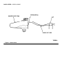
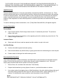
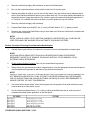
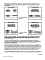
99-2, Publication Date: JANUARY 26, 1999
MEDIUM/HEAVY TRUCK:
1996-98 LOUISVILLE
ISSUE:
There may be excessive wear of either the right front or left front tire on some vehicles equipped with a 14600,
16000, 18000, or 20000 lb front axle. This may be caused by the front and/or rear axle not being
perpendicular to the frame.
ACTION:
Align front axle to be perpendicular to frame. This should reduce tire scrub. Refer to the following Service
Procedure for details.
SERVICE PROCEDURE
1.
Check total vehicle alignment.
2.
On vehicles with tandem rear axles, correct any misalignment as specified in the appropriate
Louisville/AeroMax Workshop Manual, Section 204-00, or refer to TSB «98-21-15» for vehicles
equipped with Hendrickson walking beam suspensions.
3.
If front axle camber is out-of-specification, replace I-Beam per Workshop Manual, Section 204-01.
(Refer to Workshop Manual, Section 204-00, for specification).
4.
To align the front axle, loosen the U-bolts, reposition the front axle, and torque front axle U-bolts to
the torque specified below. The front axle side-to-side variation to the rear axle should be not more
than 3mm (1/8") or the set back should be less than 0.1 degree. Reset toe to 0.8mm (1/32").
5.
3/4" U-bolts are torqued to 339-407 N-m (250-300 lb-ft).
6.
7/8" U-bolts are torqued to 542-651 N-m (400-480 lb-ft).
7.
The front axle U-bolts must be checked and tightened again after 800-1600 km (500-1000 miles).
OTHER APPLICABLE ARTICLES:
98-21-15
WARRANTY STATUS: Eligible Under Basic Warranty Coverage
LABOR ALLOWANCE
DEALER CODING
OASIS CODES: 303000, 306000, 390000
99-3, Publication Date: FEBRUARY 15, 1999
MEDIUM/HEAVY TRUCK:
1992-97 L SERIES
ISSUE:
Loose or cracked rear suspension crossmember(s) may be evident on some vehicles. This may be caused by
insufficient clamping force produced by the upper and lower bolts that attach the crossmember(s) to the
frame-mounted gusset .
ACTION:
If the crossmember is cracked, it requires replacement.
If the crossmember is loose, remove torque rod and existing attaching hardware. Enlarge the holes in
the crossmember and gusset to 20.50/21.00mm (0.807/0.827") diameter. Install the 0.75" diameter
hardware and torque the nuts to 350-400 N-m (260-300 lb-ft). If the holes in the crossmember or the
gusset are elongated larger than 19mm (0.75"), the crossmember requires replacement (part number
is located on the flange of the crossmember).
Refer to the 1996 L-Series Service Manual, Page 02-01-11, Item 3, for a representative illustration showing
the crossmember installation. Refer to the appropriate model year L-Series Service Manual for proper
installation of service parts and torque specifications.
NOTE:
ONE WASHER MUST BE INSTALLED UNDER THE BOLT HEAD AND ONE WASHER MUST BE
INSTALLED UNDER THE NUT.
OTHER APPLICABLE ARTICLES: NONE
WARRANTY STATUS: Eligible Under Basic Warranty Coverage
LABOR ALLOWANCE
DEALER CODING
OASIS CODES: 304000, 305000, 390000
99-4, Publication Date: FEBRUARY 19, 1999
MEDIUM/HEAVY TRUCK:
1996-98 AEROMAX, LOUISVILLE
ISSUE:
The radiator coolant supply tank vent hose nipple may break off at the tank connection. Engine vent hose
routing may allow the engine to pull on the tank nipple during engine articulation.
ACTION:
Replace the coolant supply tank and reroute the engine vent hose. Refer to the following Service Procedure
for details.
SERVICE PROCEDURE
1.
Replace the coolant supply tank and associated hardware. Refer to the appropriate
Louisville/AeroMax Workshop Manual, Section 303-03, or Service Manual, Section 03C-03.
2.
Loosen the engine clip as necessary where the engine vent hose line is routed through and add
25.4mm (1") slack between the hose clip and the coolant tank nipple. The vent hose is sufficiently
long to allow the 25.4mm (1") slack. Refer to «Figure 1».
3.
Retighten engine clip to retain the vent hose.
OTHER APPLICABLE ARTICLES: NONE
WARRANTY STATUS: Eligible Under Basic Warranty Coverage
LABOR ALLOWANCE
DEALER CODING
OASIS CODES: 206000, 402000
Figure 1 - Article 99-4-4
99-6, Publication Date: MARCH 19, 1999
MEDIUM/HEAVY TRUCK:
1996-98 AEROMAX, LOUISVILLE
ISSUE:
The Ready Line Access Door Spring (XC4Z-MF062A-AA) may be broken.
ACTION:
Replace the spring with a revised Spring (XC4Z-MF062A-AB).
OTHER APPLICABLE ARTICLES:
98-20-23
WARRANTY STATUS: Eligible Under Basic Warranty Coverage
LABOR ALLOWANCE
DEALER CODING
OASIS CODES: 108000, 111000, 112000, 190000
99-10, Publication Date: MAY 14, 1999
MEDIUM/HEAVY TRUCK:
1997-98 LOUISVILLE
ISSUE:
High floor heat may arise during idle with PTO in operation. During PTO operation with the vehicle stationary,
in-cab temperatures can cause driver or passenger discomfort.
ACTION:
Install a thermal/heat barrier shield under the floor trim/mats to provide additional insulation. Refer to the
following text for details.
Use Heat Barrier LF198 that can be obtained from Lydall Westex (248-952-5570, 8:00am-5:00pm EST) and
install with aluminum side down.
Material required per cab is two (2) 1.8 square meter (6 square feet) sheets. Cut to fit using floor trim as
guide. Assure sufficient clearance around brake pedal, clutch pedal, and accelerator so that operation of these
controls is not affected.
NOTE:
LIFT FLOOR MAT/TRIM UP, BEFORE PLACING HEAT BARRIER SHIELD DOWN, THEN COVER WITH
MAT/TRIM.
OTHER APPLICABLE ARTICLES: NONE
WARRANTY STATUS: INFORMATION ONLY
OASIS CODES: 101000, 107000, 111000
99-12, Publication Date: JUNE 7, 1999
FORD:
1996-97 ASPIRE, PROBE, THUNDERBIRD
1996-99 CONTOUR, CROWN VICTORIA, ESCORT, MUSTANG, TAURUS
LINCOLN-MERCURY:
1996-97 COUGAR
1996-98 MARK VIII
1996-99 CONTINENTAL, GRAND MARQUIS, MYSTIQUE, SABLE, TOWN CAR, TRACER
1999 COUGAR
LIGHT TRUCK:
1996 BRONCO
1996-97 AEROSTAR, F SUPER DUTY, F-250 HD, F-350
1996-99 ECONOLINE, EXPLORER, F-150, F-250 LD, RANGER, VILLAGER, WINDSTAR
1997-99 EXPEDITION, MOUNTAINEER
1998-99 NAVIGATOR
1999 SUPER DUTY F SERIES
MEDIUM/HEAVY TRUCK:
1996-97 CARGO SERIES
1996-98 AEROMAX, F SERIES, LOUISVILLE
This TSB article is being republished in its entirety to add vehicles and model years, and to revise the
procedure to use Ford brand service parts.
ISSUE:
Ford Motor Company has released a private labeled material to be used for iron particle/acid rain service
repairs.
ACTION:
To remove these particles/contaminates, use ONLY the following products and procedure. No polishing,
compounding, color sanding, or repainting should be done before this procedure is performed. This procedure
uses products that are acidic, alkaline, and neutral and must be properly mixed and used in their specific
order. Refer to the following Service Procedure for details.
SERVICE PROCEDURE
NOTE:
ANY CHANGES TO THIS PROCEDURE WILL CAUSE AN INCOMPLETE OR UNSATISFACTORY
REPAIR. THE USE OF ANY OTHER PRODUCT OR PROCEDURE MAY CAUSE DAMAGE TO
ALUMINUM OR PAINTED SURFACES.
NOTE:
THE PRODUCTS USED TO REMOVE SURFACE CONTAMINATION FROM PAINT ARE DESIGNED
FOR VEHICLES WHICH HAVE EXPERIENCED EXPOSURE FOR LESS THAN 120 DAYS. VEHICLES
THAT EXCEED 120 DAYS OF EXPOSURE MAY REQUIRE THE PROCEDURE BE REPEATED TO
RESOLVE THE CONCERN. ONCE THIS PROCEDURE IS COMPLETED, IT MAY BE NECESSARY TO
PERFORM POLISHING OR REFINISHING PROCEDURES AFTER VEHICLE INSPECTION.
IDENTIFICATION
Ferrous metal particles (hot iron dust) are generated by manufacturing facilities, rail shipments, etc. These
particles mechanically bond to a vehicle's painted surfaces. Moisture and temperature combine with particles
to create a chemical reaction. This reaction creates an acid, causing the iron to corrode and enter the paint
surface. Industrial fallout and acid rain generate corrosive compounds that fall on the vehicle's painted
surfaces. When subjected to moisture and temperature, chemical compounds are created that etch the paint
surface.
To assist in identifying surface contamination, use a (Tandy-Radio Shack #63-851) 30x lighted magnifier.
Concern Description
Ferrous Metal
Light Colored Vehicles: Small orange stains the size of "mechanical pencil lead." The surface is
rough to the touch.
Dark Colored Vehicles: Small white or silver appearing dots with a rainbow ring around the dot. The
surface is rough to the touch.
Industrial Fallout
Water spots with ferrous metal are present and the surface is rough to the touch.
Acid Rain/Etching
Surface will exhibit irregular discolored spotting.
Dark colored vehicles may exhibit cloudy or graying spots where the acid has begun to etch the paint.
Extreme cases of etching will be visible and may be felt.
Decontamination Procedure
Use Ford Acid Neutralizer, Alkaline Neutralizer, and Detail Wash to decontaminate and neutralize the paint
surface. Perform the procedure only on vehicle when the paint surface temperature is cool. Follow the
step-by-step procedure listed below to perform this service operation.
1.
Rinse off dust, dirt, and debris with cold water. Flush liberally.
2.
Prepare Acid Neutralizer by mixing 8 parts of water to 1 part Acid Neutralizer in a bucket.
3.
Use a clean wash mitt and apply mixture of Acid Neutralizer to the entire vehicle starting at the top of
the vehicle working toward the side. Keep the vehicle wet with solution, lightly agitating for 5 to 7
minutes. For vehicles with severe conditions, work the product for up to 8 minutes.
NOTE:
USE A SEPARATE MITT FOR EACH PRODUCT. DO NOT INTERMIX MITTS.
4.
Rinse the vehicle thoroughly with cold water to remove Acid Neutralizer.
5.
Dry only the horizontal surfaces of the vehicle at this time. Do not dry glass.
6.
Alkaline Neutralizer is ready to use. Do not mix with water. Pour the contents into a dispenser squirt
bottle. Squirt Alkaline Neutralizer directly onto a clean wash mitt. Do not spray Alkaline Neutralizer on
the painted surface. Apply the product to the vehicle, keeping the areas wet and lightly agitated for 5
to 7 minutes. For vehicles with severe conditions, work the product for up to 8 minutes.
7.
Rinse the vehicle thoroughly with cold water.
8.
Prepare Detail Wash by mixing 29.5 mL (1 ounce) of Detail Wash to 3.7 L (1 gallon) of water.
9.
Shampoo the vehicle with Detail Wash using a clean wash mitt. Rinse the vehicle with cold water and
dry the vehicle completely.
NOTE:
DETAIL WASH IS A HEAVY DUTY NEUTRAL SHAMPOO CONCENTRATE (pH 7) AND MAY BE
USED FOR HAND CAR WASHING OR IN AUTOMATIC CAR WASH SYSTEMS.
Surface Correction Following Decontamination/Neutralization
1.
Visually inspect paint surface for evidence of removal of ferrous metal particles and water spots.
NOTE:
ACID RAIN DISCOLORING OR ETCHING WILL REQUIRE ADDITIONAL PROCEDURES
DEPENDENT ON DEPTH OF DAMAGE; POLISHING, BUFFING, COLOR SANDING, OR IN
EXTREME CASES, REFINISHING.
2.
Do Not Intermix Buffing Products. Use only one manufacturer's products.
3.
Always follow the manufacturer's product usage sequence. Use the appropriate recommended pad at
recommended buffing speeds as specified by the product manufacturer.
NOTE:
WHEN ATTEMPTING TO AFFECT A REPAIR BY BUFFING, POLISHING, OR COLOR SANDING, DO
NOT REMOVE AN EXCESS OF 0.3 MIL OF PAINT FILM OR REFINISHING WILL BE REQUIRED.
USE OF AN ELECTRONIC MIL GAUGE (ROTUNDA 164-R4025) IS HIGHLY RECOMMENDED TO
INSURE CONTROL OF PAINT FILM REMOVAL.
4.
Use a dual action sander with a Velcro backing plate and a foam pad to fine polish and remove any
swirls created by a rotary buffer or pad.
5.
Use an alcohol and water mixture (1 to 1 ratio) to clean the buffed areas and to verify removal of
scratches and swirls before application of the final polish.
OTHER APPLICABLE ARTICLES: NONE
SUPERSEDES: 97-21-3
WARRANTY STATUS: Eligible Under The Provisions Of 12 Month/12,000 Mile Basic Warranty Coverage
LABOR ALLOWANCE
DEALER CODING
OASIS CODES: 106000, 190000
Figure 1 - Article 99-12-10
99-14, Publication Date: JULY 6, 1999
FORD:
1992-99 F & B SERIES
1993-97 L SERIES
This TSB article is being republished in its entirety to add model years and service parts.
ISSUE:
A vibration or "buzz" may be experienced through the throttle pedal on some vehicles equipped with an
FD1060 or FD1460 midrange Diesel engine. This may be caused by engine vibrations being transmitted up
the mechanical linkage to the throttle pedal.
ACTION:
Replace the current mechanical linkage throttle system with a revised throttle cable system. The throttle cable
system does not transmit engine vibrations to the throttle pedal. Refer to the following text for details.
The complete installation procedure for the revised throttle cable system is provided in the Service Kit.
NOTE:
THE NEW THROTTLE CABLE SYSTEM PROVIDED IN THIS TSB ARTICLE CAN BE USED ON F, B,
AND L-SERIES VEHICLES EQUIPPED WITH:
AN FD1060 OR FD1460 ENGINE WITH BOSCH INLINE (P-TYPE) FUEL INJECTION PUMP
A MANUAL OR ALLISON MT/AT AUTOMATIC TRANSMISSIONBUT CANNOT BE USED ON F, B,
AND L-SERIES VEHICLES EQUIPPED WITH:
AN ALLISON MD (ELECTRONIC) AUTOMATIC TRANSMISSION (THE MD TRANSMISSION
REQUIRES AN ELECTRONIC THROTTLE POSITION SENSOR WHICH IS CURRENTLY
MOUNTED ONTO THE THROTTLE PEDAL ASSEMBLY. THE NEW THROTTLE PEDAL
ASSEMBLY DOES NOT HAVE A PROVISION FOR MOUNTING THIS SENSOR.)
AN FD1060 160 HP ENGINE WITH THE BOSCH ROTARY-TYPE FUEL INJECTION PUMP
NOTE:
ON 1992 AND 1993 F, B, AND L-SERIES VEHICLES, SAFETY RECALL 93S72 MUST BE PERFORMED
FIRST BY AN AUTHORIZED FORD DEALER BEFORE THE NEW THROTTLE CABLE SYSTEM CAN BE
INSTALLED. THIS CABLE SYSTEM IS NOT COMPATIBLE WITH THE ORIGINAL THROTTLE RETURN
SPRING SYSTEM.
NOTE:
FOR L-SERIES VEHICLES ONLY: IF THE VEHICLE IS EQUIPPED WITH AN FD1460 ENGINE AND
OPTIONAL ETHER COLD START SYSTEM, THEN IT WILL BE NECESSARY TO RELOCATE BOTH
THE ETHER BOTTLE AND WINDSHIELD WASHER FLUID RESERVOIR. THESE COMPONENTS WILL
HAVE TO BE RELOCATED TO PROVIDE THE NECESSARY CLEARANCE FOR THE NEW THROTTLE
CABLE SYSTEM. THE NEW POSITION OF THESE COMPONENTS WILL THEN BE THE SAME AS
THAT ON VEHICLES EQUIPPED WITH THE FD1060 ENGINE. INFORMATION REGARDING
RELOCATION OF THE ETHER START SYSTEM AND WASHER FLUID RESERVOIR IS PROVIDED IN
THE SERVICE KIT.
CAUTION:
ONCE THE NEW THROTTLE CABLE SYSTEM IS INSTALLED, THE OPERATION OF THE ENTIRE
THROTTLE SYSTEM MUST BE THOROUGHLY CHECKED TO ENSURE PROPER OPERATION. WITH
THE ENGINE RUNNING, DEPRESS THE ACCELERATOR PEDAL TO ITS FULL EXTENT, THEN
SLOWLY RELEASE THE PEDAL. "SLOWLY RELEASE" MEANS MOVEMENT NO FASTER THAN
APPROXIMATELY 2 SECONDS PER INCH. THE THROTTLE PEDAL MUST RETURN COMPLETELY
TO IDLE POSITION WITHOUT ANY INDICATION OF DRAGGING OR BINDING. OTHER ENGINE
COMPARTMENT COMPONENTS (HOSE, WIRING, ETC.) MUST NOT CONTACT ANY MOVING PART
OF THE ACCELERATOR CONTROLS.
CAUTION:
THE INSTALLATION OF THE THROTTLE CABLE SERVICE KIT REQUIRES DRILLING NEW
COMPONENT MOUNTING HOLES IN THE CAB FLOOR. IT IS VERY IMPORTANT THAT ANY WIRING
HARNESSES, HOSES, AFTERMARKET ACCESSORIES, ETC. THAT MAY INTERFERE WITH THE
DRILLING OPERATION BE TEMPORARILY REPOSITIONED OR REMOVED. THE FLOOR PAN AREA
INSIDE AND OUTSIDE OF THE CAB MUST BE CHECKED TO MAKE SURE SUFFICIENT CLEARANCE
IS OBTAINED.
The Throttle Cable Retrofit Kit (F7HZ-9728-BA) for F- and B-Series vehicles contains the following:
One (1) Engine Bracket
One (1) Throttle Cable
One (1) Engine Lever
One (1) Throttle Pedal
One (1) Dust Shield
Three (3) 1/4" Bolts
Six (6) 1/4" Nuts
Six (6) 1/4" Washers
The Throttle Cable Retrofit Kit (F8HZ-9728-BA) for L-Series vehicles contains the following:
One (1) Engine Bracket
One (1) Throttle Cable
One (1) Engine Lever
One (1) Throttle Pedal
One (1) Dust Shield
Three (3) 1/4" Bolts
Seven (7) 1/4" Nuts
Seven (7) 1/4" Washers
Install a Cover Plate (F7HZ-80113A52-AA) over the hole in the cab floor previously utilized by the linkage
mechanism. The cover plate should be attached to the cab floor by four (4) Screws (55927-S2).
OTHER APPLICABLE ARTICLES: NONE
SUPERSEDES: 97-20-22
WARRANTY STATUS: Eligible Under Basic Warranty Coverage
LABOR ALLOWANCE
DEALER CODING
OASIS CODES: 497000, 703000, 703100, 703200, 703300