1
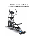
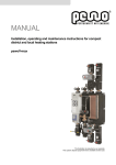
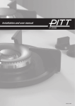
LS13.0E-02 Service Manual 1 TABLE OF CONTENTS CHAPTER 1: SERIAL NUMBER LOCATION 1.1 Serial Number Location………………………………………………….….……………………………….……3 CHAPTER 2: ENGINEERING MODE 2.1 Engineering Mode…………………………………….………………………………………….….…………….4 2.2 Engineering Mode Overview…………………………………………….…………………………..………..….5 CHAPTER 3: ELECTRONIC DIAGRAMS 3.1 Electronic Diagram…………………………………….………………………..……………………….…….….6 CHAPTER 4: TROUBLE SHOOTING 4.1 Troubleshooting – No RPM Displayed…………………………………………………………………………..7 4.2 Troubleshooting – No Resistance or Incorrect Resistance……………………………………………...……8 4.3 Troubleshooting – No Power to the Console………………………………………………………………….10 4.4 Troubleshooting – No or High Heart Rate……………………………………………………………………..11 4.5 Troubleshooting – Knocking or Creaking Noises……………………………………………………………..12 2 CHAPTER 1: SERIAL NUMBER LOCATION 1.1 Serial Number Location 3 CHAPTER 2: ENGINEERING MODE 2.1 Engineering Mode 1) To enter Engineering Mode, press & hold the LEVEL UP and DOWN keys at the same time for 3-5 seconds until Engineering Menu appears on the display. 2) Use the LEVEL UP and DOWN keys to scroll through a list of parameters. 3) Press the CHANGE DISPLAY / ENTER key to enter a parameter setting. 4) Use the LEVEL UP and DOWN keys to change the parameter and ENTER to save. 5) Press and hold the STOP key to exit Engineering Mode and return to normal operation. 4 CHAPTER 2: ENGINEERING MODE 2.2 Engineering Mode Overview Mode Function Description GO LCD on Eng 0 STOP LCD off Display Test Press any other key to test for function. Hold “STOP” 3 sec back to “Engineering Menu” Press ENTER to scroll through the options in this menu and LEVEL UP or DOWN to test or change the settings / components below. ECB Count – Allows testing of the ECB motor. Eng 1 Incline – Allows testing of the incline motor. Hardware Test Heart – Allows for testing of the heart rate. MCB Ver – Shows the software version of the MCB. Not Editable. USB On / Off – This setting will automatically display on or off depending on if there is a USB in the USB port. Hold “STOP” 3 sec back to “Engineering Menu” Use INCLINE up and down to choose SPEED MODE. Eng 2 Switch Function ENTER Use INCLINE up and down to switch EUP on or off. ENTER Use INCLINE up and down to choose US or ID Hold “Stop” 3 sec back to “Engineering Menu” Press ENTER to scroll through the options in this menu and LEVEL UP or DOWN to test or change the settings / components below. Eng 3 Information Speed Mode – Miles or Kilometers. EUP On / Off – EUP = Energy Using Products Directive. Machine Set – Set the region of the customer (US or ID (international)). Hold “Stop” 3 sec back to “Engineering Menu” While in ENG2, Hold LEVEL UP and DOWN for 3 sec to enter ENG8. P0 in distance window = the current software P1 in distance window = accelerated ratio (factory only setting). ENG8 P3 in distance window = Hold START key for 3 sec to clear all console data. P4 in distance window = Burn Time (factory only setting). Hold “Stop” 3 sec back to “Engineering Menu” ※ “START” key to save the change. 5 CHAPTER 3: ELECTRONIC DIAGRAMS 3.1 Electronic Diagram 6 CHAPTER 4: TROUBLESHOOTING 4.1 Troubleshooting – No RPM Displayed Symptom: No RPM shown on the console. Reason: 1. Bad connection between the console cable and the console or a damaged cable. 2. The speed sensor wire is damaged or not working. 3. The magnet is not present on the drive pulley. 4. The console is defective. Solution: 1. Check the connection of the console cable at the console; make sure there are no kinks or pinches of the console cable. Replace the cable if any damage is found. 2. Check the connection of the speed sensor wire at the ECB motor. Also check the gap between the speed sensor and the magnet on pulley. It should be within 5mm. Adjust the gap if it is too big. 3. Install a new magnet. 4. Replace the console set. 7 CHAPTER 4: TROUBLESHOOTING 4.2 Troubleshooting – No Resistance or Incorrect Resistance Symptom:1. The resistance is not adjustable during an exercise. 2. The resistance is reverse or much too heavy. Reason: 1. The speed sensor wire is defective. 2. The console cable or ECB motor is defective. 3. The steel rope of the magnet system is not routed correctly. 4. The inside magnet is defective. Solution: 1. Check if the console shows RPM value. If it does not, refer to troubleshooting for NO RPM DISPLAYED in Section 4.1. 2. Remove the front shrouds. Turn on the console, and check the ECB motor. At resistance level 1, the head of the steel rope should point towards the top right side (around 45 degrees). If the head of the steel rope points toward the bottom or left side, the resistance will be reversed, adjust the head of the steel rope to the correct position. 3. Press the LEVEL UP key to adjust the resistance. a. If the ECB motor does not move, the resistance will not be changed. The ECB motor or console cable is defective. Check the console cable connection at the ECB motor. Use a multi-meter to measure the voltage through the console cable. It should be 12VDC. b. If there is no voltage present, the console cable is defective. Replace the console cable. c. If the voltage is 12VDC, the ECB motor is defective. Replace ECB motor. 8 CHAPTER 4: TROUBLESHOOTING 4.2 Troubleshooting - No Resistance or Incorrect Resistance - Continued d. If the ECB motor does move, the resistance can be adjusted. If the resistance is still too heavy, check the gap between the orange block and the bottom of the ECB track. It should be within 1-2 mm of the bottom of the ECB track. If the gap is bigger than 1-2 mm, the resistance will be heavier than normal. Adjust the cable to the correct gap range. 4. If all above conditions are ok, and the resistance is still too heavy, the magnet inside the ECB is defective. Replace the ECB. 9 CHAPTER 4: TROUBLESHOOTING 4.3 Troubleshooting – No Power to the Console Symptom: Console does not light up. Reason: 1. The power adaptor is not correct or is defective. 2. The console cable has a bad connection or is defective. 3. The console is defective. Solution: 1. The adaptor for this model is 12V - 1A. Check to make sure the power adaptor on the unit is correct. Test the power adaptor on a known good outlet. Replace the adaptor if it is defective. 2. Check the connection of the console cable at the console. Unplug the console cable from console, and use a multi-meter to check the voltage through the console cable. Normally it should be 12VDC. If no voltage is present, the console cable is defective, replace it. 3. If the voltage through the console cable is 12VDC, the console is defective, replace it. 10 CHAPTER 4: TROUBLESHOOTING 4.4 Troubleshooting – No or High Heart Rate Symptom: No heart rate or the heart rate is consistently too high. Reason: 1. The heart rate grips are not connected properly or are defective. 2. The heart rate grip wiring is damaged or not connected correctly. 3. The HR board or console is damaged. Solution: 1. With a multi-meter set for DC voltage, place one terminal on each of the HR grip plates. The HR grip should give a voltage reading of between 0.5 and 2.0VDC. a. If the voltage is not between 0.5 and 2.0VDC, remove the 3 screws holding the HR grip together and check the connection of the HR grip wiring. 2. Check continuity of the HR grip wiring. a. Place one terminal of a multi-meter set for resistance on the HR grip wiring at the HR grip, and the other terminal on the HR grip wiring at the console. An ohm reading of around 1 should be expected, if the reading is higher than 1, replace the HR grip wiring. 3. If the HR grips and HR grip wiring do not solve the issue, replace the console. 11 CHAPTER 4: TROUBLESHOOTING 4.5 Troubleshooting – Knocking or Creaking Noises Symptom: Knocking or creaking noises during workout. Reason: 1. There is hardware that is not tight or is missing. 2. The noise is related to the incline. 3. The belt tension is not high enough, or the belts are dirty. Solution: 1. Inspect the unit and check for any loose hardware. Pay special attention to areas where arms meet. Tighten hardware where needed. 2. If the noise is present only during incline, check to make sure the Teflon washers are installed at the incline motor connection point (Figure A). a. Lubricate the gear shaft of the incline motor with grease (Vision recommends Super Lube brand Lithium Grease where available). 3. Remove the covers and check the belt tension. a. Tighten the drive belt tension if needed by moving the spring tension clip to another hole 4) Clean the belts. If they are worn or will not clean, replace the belts. FIGURE A 12