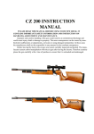
1
ATTENTION:
This operator’s manual should be read carefully before
using the rifle!
Observe the regulations of the ISSF during adjustments.
ENGLISH
NOTE:
23
All firearms are dangerous objects, storage and use of which
demand utmost caution.
1.
Technical Data . . . . . . . . . . . . . . . . . . . . . . . . . . . 26
Always treat an unloded weapon as if it were loaded.
2.
Cocking, loading and shooting . . . . . . . . . . . . . 27
Never put your finger on the trigger, except when actually
firing a shot. Always ensure that the weapon is pointing in a
safe direction. Keeping the weapon in perfect condition
insures safety.
3.
Sight adjustment
4.
4.1
4.2
4.3
4.4
Trigger adjustment . . . . . . . . . . . . . . . . . . . . . . . 29
First stage travel adjustment . . . . . . . . . . . . . . . . . 29
First stage weight and single . . . . . . . . . . . . . . . . . . .
stage trigger adjustment . . . . . . . . . . . . . . . . . . . . 30
Second stage weight adjustment . . . . . . . . . . . . . 31
Trigger blade adjustment . . . . . . . . . . . . . . . . . . . . 32
5.
Dry firing mechanism . . . . . . . . . . . . . . . . . . . . . 33
6.
Butt plate adjustment . . . . . . . . . . . . . . . . . . . . . 34
7.
Pich adjustment . . . . . . . . . . . . . . . . . . . . . . . . . . 35
8.
Replacing and refilling the . . . . . . . . . . . . . . . . . . .
compressed-air cylinder . . . . . . . . . . . . . . . . . . . 36
9.
Cleaning and care . . . . . . . . . . . . . . . . . . . . . . . . 36
10.
Guarantee clauses
11.
Parts list LG 20
Weapons always have to be stored out of the reach of
unauthorized persons.
24
TABLE OF CONTENT
. . . . . . . . . . . . . . . . . . . . . . . . 28
ENGLISH
ENGLISH
IMPORTANT MEASURES FOR HANDLING OF FIREARMS
. . . . . . . . . . . . . . . . . . . . . . . 37
. . . . . . . . . . . . . . . . . . . . . . . . . . 39
25
TECHNICAL DATA
Caliber.......................................... 4,5 mm (.177)
ENGLISH
Overall height .............................. 195 mm - 235 mm
.................................................... (without sight)
Overall length .............................. 1008 mm - 1117 mm
2
COCKING, LOADING AND SHOOTING
Pull back the loading gate all the way to the rear, this cocks
the rifle and opens the loading port of the barrel.
Insert a pellet and fully close the loading gate. The rifle is
ready for firing.
ENGLISH
1
Overall width ................................ 52 mm
Sight length .................................. 700 mm - 875 mm
Barrel length ................................ 420 mm
Total weight without additional
weights and sight heights ............ appr. 4030 g
Maximum filling pressure ............ 200 bars
Power max .................................. 7,5 Joules
26
27
SIGHT ADJUSTMENT
TRIGGER ADJUSTMENT
The setscrews have to be turned on the rear sight as follows:
Please note:
High hit
turn height-adjusting knob direction "H"
The trigger has the following individual adjustments:
Low hit
turn height-adjusting knob direction "T"
First stage travel adjustment
Right hit
turn side-adjusting knob in direction "R"
First stage weight and single stage trigger adjustment
Left hit
turn side-adjusting knob in direction "L"
Second stage weight adjustment
Trigger blade adjustment
The length of sight is individually adjustable by moving the
rear sight and front sight tunnel. Optional: The rear and front
sight are adjustable for lateral offset and height due to different
distance discs. In addition it can be moved laterally up to
7 mm.
28
4
Please note:
If adjustments of front and rear sight
heights are at the maximum of 60 mm
(middle of front sight to middle of barrel)
the riser blocks of rear sight must be 2.75
mm (smallest additional disc) higher than
front sight!
Please note:
You must use the right length of screw, if
too long of a screw is used, then surface of
the housing will be damaged!
Before making any changes on the trigger,
ensure that the weapon is unloaded!
ENGLISH
ENGLISH
3
4.1 First stage travel adjustment
Turning the screw
clockwise = shorter first stage travel
counter-clockwise = longer first stage travel
29
4.2 First stage weight and
4.2 single stage trigger adjustment
4.3 Second stage weight adjustment
Turning the screw
Turning the screw
30
To get a single stage trigger, turn the screw counter-clockwise
completely until first stage pressure is equal to zero.
clockwise = heavier second stage pull
anti-clockwise = lighter second stage weight
ENGLISH
ENGLISH
clockwise = higher first stage pressure
counter-clockwise = lower first stage pressure
31
4.4 Trigger blade adjustment
5
Loosen countersunk screw A, the trigger blade may be
moved in height and rotated.
The loading gate is pulled backwards to the stop and then be
moved forward again until the first resistance is felt.
Loosen countersunk screw B, the trigger blade may be
moved longitudinally and can be angled.
If the rifle already cocked, the dry firing mechanism can be
used by opening the loading gate only.
ENGLISH
ENGLISH
DRY FIRING MECHANISM
32
33
CHEEK PIECE ADJUSTMENT
ENGLISH
Screw A allows the cheek piece to be adjusted in height.
Loosening screws B, the cheek piece can be moved laterally and turned.
Loosening screw C, the cheek piece can be angled.
7
BUTT PLATE ADJUSTMENT
The plate of the butt
plate can be adjusted in 2 different
heights by loosening screws A.
ENGLISH
6
Screw B allows the
butt plate to be
moved in length
and swifeled.
After loosening
screws C, the butt
plate can be moved
laterally.
Additionally the plate
can be adjusted in
two different angles:
90° and 80°.
34
35
REPLACING AND REFILLING THE
COMPRESSED-AIR CYLINDER
The legal requirements and rules of the respective country
must be adhered to. Compressed-air cylinders have to be
inspected after 10 years exclusively by the manufacturer. It is
the responsibility of the customer to return the cylinder to the
manufacturer. The compressed-air cylinder may be unscrewed and removed at any time without being emptied.
WARNING:
Do not tamper with compressed-air cylinder and valve. It may cause injury!
The compressed-air cylinder is to be charged with a maximum
filling pressure of 200 bar. For recharging the cylinder proceed
as follows:
either mount the compressed-air cylinder on a recharging
bottle
or mount the compressed-air cylinder on a hand pump
or mount the compressed-air cylinder on a compressor
9
GUARANTEE CLAUSES
If within two years from the day of purchase any cracks or
breaks should occur on this weapon that are due to material
failure we undertake repair the defective parts free of charge
(except breakage or cracking of the stock or O-rings).
Guarantee will be given by either replacing or repairing the
weapon or parts of it at our sole discretion. The guarantee is
only valid if the fully completed guarantee card is returned immediately after purchasing the weapon.
No guarantee claims will be accepted by the SteyrSportwaffen GmbH if:
a)
the weapon has been damaged or destroyed by force
majeur or environmental influences;
b)
in case of damages/defects having been caused by
improper treatment, or handling or by lack of care.
c)
if the weapon has been repaired, machined or altered
by any person or workshop other than an authorised
Steyr Sportwaffen GmbH workshop.
CLEANING AND CARE
In standard use the weapon operates maintenance-free and
no oiling is required.
The only maintenance required is to slightly grease the O-ring
in the loading port and the O-ring at the threaded adapter sokket for the compressed-air cylinder with a special lubricant
(acid-free silicone grease) every 1000 shots. This will increase the service life of the O-rings.
To clean the barrel shoot some felt pellets or cleaning strings
through the barrel (available at your dealer).
36
10
ENGLISH
ENGLISH
8
Claims for damages and product liability:
No claims for direct or indirect damages will be accepted.
Liability for material damages resulting from the product liability law, BGBL 99/1988, as well as any product liability claims
that could be derived from other provisions are excluded.
The object of purchase warrants only that type of safety which
may be expected in accordance with the homologation rules,
service manual, manufacturer's instructions as well as any
other pertinent information received.
37
Guaranteed Steyr Sportwaffen accuracy:
Our barrels are made from high quality barrel steel and are
produced according to the latest findings in barrel production
technology. Our weapons are well known for their outstanding
accuracy. However, the accuracy of a weapon depends on
several factors; one of the most important factors is the
ammunition used. Not every ammunition "fits" every barrel
equally good.
If you follow our suggestion, we guarantee that you will achieve outstanding accuracy with your new product.
38
11
PARTS LIST LG 20
No.
Designation
1
2
3
4
5
6
7
9
11
12
13
14
15
16
17
18
19
20
21
22
23
24
25
27
28
30
32
33
34
35
36
Reciever LG 20
Sear catch link
Sear
Trigger carrier
Weight cam
Pointed Allen head screw M4
Valve complete
Cam
Cam pin
Loading Gate LG-10
Valve bolt combination
Bolt
Catchlink Lever
Catch lever
Stabilizer LG 20
Compressed air cylinder
O-Ring 8x1,65
Valve Cover
O-Ring 7x2
Pressure spring
Cylinder valve
Supporting ring (brass)
Cylinder valve compl.
O-Ring 2,9x1,8
O-Ring 24x2
pressure gauge
Trigger blade
Trigger axis
Allen set screw M3x5 DIN 913
Allen set screw M3x3 DIN 913
Countersunk screw M3x8 DIN 964
ENGLISH
ENGLISH
The above clauses govern the full customer/manufacturer
relationship with our company. Any additional claims, in particular for any kind of damages or losses caused by the weapon or its use, are excluded.
39
Designation
No.
Designation
37
38
40
41
42
43
44
45
46
47
48
49
50
51
52
53
54
55
56
57
58
59
60
61
62
63
64
65
66
67
68
69
Bellview washer 10
Trigger post assy
Allen set screw M6x8 DIN 553
Allen set screw
Draw spring
Draw spring
Torsion spring
Washer - STARLOCK
Parallel pin 3m6x24 DIN 6325
O-Ring 6x2
Pressure spring
Barrel cover
Cam screw
Allen set screw
cover for Stabilizer
Detent Ball 2mm III-ST-stainless
Parallel pin 1,5m6x7 DIN 6325
Pressure spring G.K. VD-085
Pressure spring D-117H-51
Pressure spring
Allen set screw M3x10 DIN 913
Parallel pin 2m6x8 DIN 6325
Parallel pin 2,5m6x20 DIN 6325
Lock
Allen set screw
Cheek piece rod
Cheek piece carrier
Allen head cap screw M5x16 DIN 912
Thread insert M4
Allen head cap screw M4x12 DIN 912
Stock LG 20
Rail
70
71
72
73
74
75
76
77
78
79
80
81
82
83
84
85
86
87
88
89
90
91
92
93
94
95
96
97
98
100
101
102
Screw 4x20
Stock clamp socket
Cheek piece
Butt plate mount Anschütz
Butt rod
Butt plate mount
Clamp piece
Butt plate alu
Allen head cap screw M5x14 Din 912
Washer M5,3 A DIN 125
Allen head cap screw M5x12 DIN 912
Screw M3,5x45
Velocity Set screw
Allen set screw M5x5 DIN 913
Barrel Support
O-Ring 36x2
Allen set screw M5x6 DIN 913
Washer M5,3 DIN 9021
Allen head cap screw M5x16 DIN 912
Allen head cap screw M5x35 Din 912
Spring
O-Ring 3x1,5
O-Ring 1,5x1
Adjusting screw
Guiding sleeve
Cover
Screw M3,5
Regulator housing front LG-100
Regulator piston compl.
O-Ring 8,92x1,83
Bellview washer 12,5
Screen
ENGLISH
ENGLISH
40
No.
41
Designation
103
104
105
106
107
108
109
110
111
112
113
114
115
119
120
121
122
126
127
128
129
130
131
132
133
134
135
136
137
138
139
141
142
Regulator housing back
O-Ring 18x2
Barrel
O-Ring 5,28x1,78
Sight carrier
Plastic front sight
Front sight set screw
Front sight tunnel
Set washer 3,2
Screw M3x20
Clamp piece
Barrel cover weight
Cover
Adjusting cap (T-H)
Spring loaded pin
Adjusting cap (L-R)
Clamp piece
Screw M3,5
Rear sight mounting
Diopter washer
Pressure spring
Guide ring compressed air
Allen head cap screw 2,5m6x16
Pressure spring
Bushing sleeve
Parallel pin
Circlip 1,5
Allen head cap screw
Filling adapter
O-Ring 13x2
Hammer LG-20
Screw
Washer
Complete components:
1.1
Sight carrier complete
3.1
Receiver complete
3.2
Trigger blade complete
6.1
Stock complete
6.2
Cheek piece complete
6.3
Butt plate complete
6.4
Barrel support complete
8.1
Regulator complete
9.1
Compressed air cylinder complete
9.2
Cylinder valve complete
9.3
Filling adapter complete
9.4
Front sight tunnel complete
9.5
Rear sight complete
ENGLISH
ENGLISH
42
No.
43
44
ENGLISH