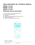
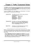
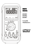
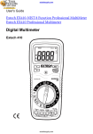
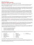
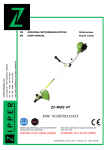
1
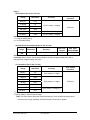
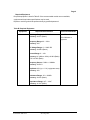
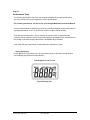
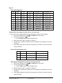
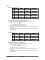
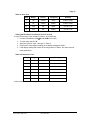
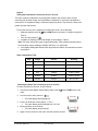
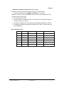
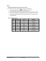
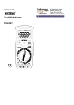
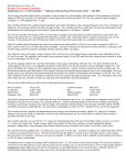
IDEAL INDUSTRIES, INC.
TECHNICAL MANUAL
MODELS: 61-312
61-314
The Service Information provides the following information:
●
Precautions and safety information
●
Specifications
●
Basic maintenance (cleaning, replacing the battery and fuses)
●
Performance test procedures
●
Calibration and calibration adjustment procedures
Form Number: TM61312-4
Revision: 2. Date: August 2007
Form Number TM61312-4
Rev 2 Aug 2007
TABLE OF CONTENTS
Page
Introduction
1
Precautions and Safety Information
1
Symbols
1
Safety
2
Specifications
3
General Specification
3
Measurement Characteristics
4
Voltage Specification
4
Current Specifications
5
Resistance, Diode, Continuity, Capacitance Specifications
6
Frequency, Temperature Specification
7
Auto Power Off, Data Hold
7
Physical and Environmental Characteristics
8
Certifications and Compliances
8
Required Equipment
9
Basic Maintenance
10
Opening the Meter Case
10
Replacing the Battery
10
Replacing Fuses
11
Fuse Replacement
11
Cleaning
11
Performance Tests
12
Testing the Display
12
Testing the Voltage Function
13
Testing the DC Current Functions
14
Testing the AC Current Functions
14/15
Testing the Resistance Function
16
Testing the Capacitance, Diode, Continuity Functions
17
Testing the Frequency Function
17/18
Testing the Temperature Function
18
Calibration
19
Calibrating Adjustment, DCV, ACV DCA and Temperature Functions
Form Number TM61312-4
Rev 2 Aug 2007
19/20
Page 1
Introduction
Warning
To avoid shock or injury, do not perform the verification tests or calibration procedures
described in the manual unless you are qualified to do so.
The information provided in this document is for the use of qualified personnel only.
Caution
The 61-312 and 61-314 series contain parts that can be damaged by static discharge.
Follow the standard practices for handling static sensitive devices.
For additional information about IDEAL INDUSTRIES, INC. and its products, and services, visit
IDEAL INDUSTRIES, INC. web site at:
www.idealindustries.com
Precautions and Safety Information
Use the meter only as described in the Service Manual. If you do not do so, the protection
provided by the meter may be impaired. Read the “Safety Information” page before servicing this
product.
In this manual, a Warning identifies conditions and actions that pose hazard (s) to the user; a
Caution identifies conditions and actions that may damage the meter or the test instruments.
The Symbols
The symbols used on the meter and in this manual are explained in Table A.
Table A. The Symbols
Risk of electric shock
Refer to the manual. Important information.
DC measurement
Equipment protected by double or reinforced
insulation
Battery
Earth
AC measurement
Conforms to EU directives
Form Number TM61312-4
Rev 2 Aug 2007
Page 2
SAFETY
Review the following safety precautions to avoid injury and prevent damage to this product or
any products connected to it. To avoid potential hazards, use the product only as specified.
For operating instructions, see the 61-312 / 61-314 Digital Multimeter Instruction Manual.
CAUTION: These statements identify conditions or practices that could result in damage to
the equipment or other property.
WARNING: These statements identify conditions or practices that could result in personal
injury or loss of life.
Use proper Fuse. To avoid fire hazard, use only the fuse type and rating specified for this
product.
Do not operate without covers. To avoid personal injury, do not apply any voltage or current to
the product without covers in place.
Do not Exceed the maximum rated input limits, as marked on the meter.
Electric overload. Never apply a voltage to a connector on the product that is outside the range
specified for that connector.
Avoid electric shock. To avoid injury or loss of life, do not connect or disconnect probes or test
leads while they are connected to a voltage source.
Do not operate in wet/damp conditions. To avoid electric shock, do not operate this product in
wet or damp conditions.
Use great care when you are required to make measurements on live circuits that exceed 50V.
Form Number TM61312-4
Rev 2 Aug 2007
Page 3
SPECIFICATIONS
All specifications are warranted unless noted typical and apply to the 61-312 & 61-314
Stated accuracies are at 23°C±5°C at less than 80% relative humidity and without the battery
indicator displayed.
General specifications
Characteristics
Description
Display count
3 3/4 digit liquid crystal display, max count 3999
Numeric update rate
1.5 times / sec
Polarity display
Automatic
Over range display
“OL” is displayed
Low battery indicator
is indicated
Automatic power-off time
Automatic backlight off ≈ 15minutes
Power source
1.5V AAA ×2 battery for 61-312
9.0V battery: types- NEDA 1604, JIS006P, IEC6F22 for
61-314
*Maximum input voltage
600Vrms CAT II between V and COM
*Maximum floating voltage
600Vrms CAT II between any terminal and earth ground
Maximum input current
400mA between mA and COM
Overload protection mA connector
500mA (250V) fast blow fuse.
Overload protection 10A connector
10A (250V) fast blow fuse.
V connector
V
Temperature Coefficient
0.1×(Spec. Accuracy) per °C, <18°C or >28°C
Battery Life
Alkaline 1.5V×2 AA, ≈ 200 hours for 61-312 Alkaline 9V, ≈
200 hours for 61-314
Form Number TM61312-4
Rev 2 Aug 2007
,V
, Ω,
,
,
, Hz, mA, Temp
Page 4
Measurement Characteristics
Accuracy is ±(% reading + number of digits) at 23°C ± 5°C, less than 80% R.H.
(1) DC Volts(for 61-312 / 61-314)
Range
Resolution
400.0mV
0.1mV
4.000V
1mV
40.00V
10mV
400.0V
100mV
600V
1V
Accuracy
Over voltage
protection
±(0.8% reading + 4 digits)
600V rms
Accuracy
Over voltage
protection
Input Impedance: 10MΩ
(2a) AC Volts (61-312 only)
Range
Resolution
4.000V
1mV
40.00V
10mV
400.0V
100mV
600V
1V
50-60Hz
1.2% + 5
40-400Hz
1.5% + 5
600V rms
Input Impedance: 4.5MΩ
AC Conversion Type: 61-312: Average sensing rms indication calibrated to the sine wave
input.
(2b) AC Volts (61-314 only)
Range
Resolution
4.000V
1mV
40.00V
10mV
400.0V
100mV
600V
1V
Accuracy
50-60Hz
1.2% + 8
40-400Hz
1.5% + 8
Over voltage
Protection
600V rms
Input Impedance: 4.5MΩ
AC Conversion Type:61-314 model only: AC conversion is ac-coupled, True RMS responding,
calibrated to a sinusoidal waveform
Crest Factor: C.F. = Peak/RMS
For non-sinusoidal waveform, C.F. > 2 add ±1% to accuracy,
Form Number TM61312-4
Rev 2 Aug 2007
Page 5
(3a) DC micro-amp and milli-amps (for 61-312 / 61-314)
Range
Resolution
400.0µA
0.1μA
4000µA
1μA
40.00mA
10μA
400.0mA
0.1mA
Accuracy
Input Prodection
±(1.2% reading + 5 digits)*
500mA, 250V Fast
Blow Fuse
Overload Protection: mA Input: 500mA, 250V Fast Blow fuse. (61-312 / 61-314)
(3b) DC Current (61-312 / 61-314)
Range
Resolution
4.000A
.001mA
10.00A*
.01mA
Accuracy
Input Protection
±(1.5% reading + 5 digits)
10A, 250V
Fast Blow Fuse
Overload Protection: A Input: 10A, 250V Fast Blow fuse. (61-312 / 61-314)
* Caution: Do not make high current measurements on the 10A scale for longer that 15 seconds.
This should be followed by a 15 minute cool down period. Exceeding 15 seconds may cause damage
to the meter and/or the test leads.
(4a) AC micro-amp and milli-amps Current (61-312 / 61-314)
Range
Resolution
400.0µA
0.1μA
4000µA
1μA
40.00mA
10μA
400.0mA
0.1mA
Accuracy
±(1.5% reading + 5 digits) *1
40Hz ~ 400Hz
Input Protection
500mA, 250V
Fast Blow Fuse
Overload Protection: mA Input: 500mA, 250V Fast Blow fuse. (61-312 / 61-314)
(4b) AC Current (61-312 / 61-314)
Range
Resolution
Accuracy
Input Protection
4.000A
.001mA
10.00A*
.01mA
±(2.0% reading + 5 digits) *1
40Hz ~ 400Hz
10A, 250V
Fast Blow Fuse
Overload Protection: A Input: 10A (250V) Fast Blow fuse.
AC Conversion Type: AC conversions are ac-coupled, true rms responding, calibrated to the
sine wave input.
*1 The specified accuracy is for sine wave at full scale and non-sine wave at half scale with crest
factor up to 2.
* Caution: Do not make high current measurements on the 10A scale for longer that 15 seconds.
This should be followed by a 15 minute cool down period. Exceeding 15 seconds may cause damage
to the meter and/or the test leads.
Form Number TM61312-4
Rev 2 Aug 2007
Page 6
(5) Resistance (for 61-312 / 61-314)
Range
Resolution
400.0Ω *1
0.1Ω
4.000KΩ
1Ω
40.00KΩ
10Ω
400.0KΩ
100Ω
4.000MΩ
40.00MΩ *
2
Over voltage
protection
Accuracy
±(1.0% reading + 4 digits)
250V rms
1KΩ
±(1.2% reading + 4 digits)
10KΩ
±(1.5% reading + 5 digits)
Open circuit Voltage: -1.5V approx.
*1 < 5 digit of reading rolling.
*2 < 2% of reading rolling.
(6) Diode Check and Continuity (for 61-312 / 61-314)
Range
Resolution
Accuracy
Max. Test
Current
Max. Open
Circuit Voltage
1mV
Not specified *
<1mA, approx.
1.5V, approx.
Overload Protection: Not specified
Continuity: Built-in buzzer sounds when resistance is less than approximately 30 Ω with a
response time of approximately 100 msec.
(7) Capacitance (for 61-312 / 61-314)
Range
Resolution
4.000nF *1
1pF
40.00nF
10pF
400.0nF
100pF
4.000μF
1nF
40.00μF
10nF
100μF
Accuracy
Over voltage
Protection
±(3% reading + 5 digits)
±(3% reading + 5 digits)
250V rms
100nF
1
4.000mF *
1
40.00mF *
1μF
10μF
±(5% reading + 20 digits) *2
1
* In this range the accuracy is not applicable and the reading maybe rolling within specification.
*2 Specify reading < half full scale of range.
Note: The meter selects the proper range automatically. Each measurement takes about
one second per range. Readings >40.00μF will take ≈ 8 seconds or greater
Form Number TM61312-4
Rev 2 Aug 2007
Page 7
(8) Frequency (for 61-312 / 61-314)
Range
Resolution
10.00Hz
.01Hz
100.0Hz
.1Hz
1.000KHz
1Hz
10.00KHz
10Hz
100.0KHz
100Hz
1.000MHz
1KHz
10.00MHz
10KHz
Accuracy
Overload
protection
Frequency:
(±0.3% + 4 digits)
250V rms
Sensitivity
1V rms
5V rms
(9) Temperature: Type K thermocouple (for 61-312 / 61-314)
Range
Resolution
Accuracy
-20 to 300 ºC
1º
±1.0% + 4
301 to 750 ºC
1º
±3.0% + 5
-4 to 572 ºF
1º
±1.0% + 4
573 to 1382ºF
1º
±3.0% + 5
Overload
protection
Not Specified
(10) Auto Power Off (APO)
If the meter idles for more than ≈ 15 minutes, the meter automatically turns the power off.
(11) Data Hold
Press the HOLD button to freeze the reading in the display, “H” will appear on LCD display.
Press the HOLD button again to release the data hold function.
Form Number TM61312-4
Rev 2 Aug 2007
Page 8
Physical and Environmental Characteristics
Characteristics
Description
Dimensions (H×W×D)
150mm(H) ×76mm (W) ×38mm(D) (with holster)
5.9” (H) x 3.0”(W) x1.5”(D)
Weight (with battery& holster)
0.219Kg (7.1 oz.)
Environmental characteristics
Description
Temperature operating
0 to +40°C
Non-Operating
-20 to +60°C <80% R.H.
Humidity (operating)
<70% R.H.
Altitude
6561.7 Ft. (2000m)
Indoor Use
Indoor Use
Certifications and compliances
Safety
Complies with UL 61010B-1
Input Safety Rating
V / Ω/Temp/mA, UL 61010B-1, UL 61010-B-2-031, EU
61010-1 EN61010-2-031, Cat IV 600Volts, Cat III 1000V
CAT IV: Service drop to service entrance,
CAT III: Distribution level mains, fixed installation.
CAT II: Local level mains, appliances, portable equipment
CAT I: Signal level, special equipment or parts of equipment,
telecommunication, electronics.
Pollution Degree 2
Do not operate in environments where conductive
Pollutants may be present.
Meets the intent of Directive 89/336/EEC for Electromagnetic
Compatibility and Low Voltage Directive 73/23/EEC for product
safety. Compliance was demonstrated to the following specifications
as listed in the official Journal of the European Communities:
EC Declaration
of Conformity
En 55011 Class A: Radiated and Conducted Emissions.
En 50082-1 Immunity:
IEC 801-2 Electrostatic Discharge
IEC 801-3 RF Radiated
En 61010-1 Safety requirements for electrical equipment for
measurement, control, and laboratory use.
Form Number TM61312-4
Rev 2 Aug 2007
Page 9
Required Equipment
Required equipment is listed in Table B. If the recommended models are not available,
equipment with equivalent specifications may be used.
Repairs or servicing should be performed only by qualified personnel.
Table B. Required Equipment
Equipment
Calibrator
Required Characteristics
AC Voltage Range: 0 ~ 750V AC
Accuracy: ±0.07% (Basic)
Frequency Range: 40 ~ 1KHz
Accuracy: ±2%
DC Voltage Range: 0 ~ 1000V DC
Accuracy: ±0.006% (Basic)
Current Range: 0 ~ 10A
Accuracy: AC (40Hz to 1KHz): ±0.08% (Basic)
DC: ±0.02% (Basic)
Frequency Source: 5.00Hz ~ 100MHz
Accuracy: ±0.001%
Amplitude: 0.5V p-p ~ 1.0V p-p (square wave)
Accuracy: ±5%
Resistance Range: 1Ω ~ 100MΩ
Accuracy: ±0.03% (Basic)
Capacitance Range: 1pF ~ 10mF
Accuracy: ±0.10% (Basic)
Form Number TM61312-4
Rev 2 Aug 2007
Recommended Model
Fluke 5500 or Wavetek
9100 Calibrator or
equipment
Page 10
Basic Maintenance
Warning
To avoid shock, remove the test leads and any input signals before opening the case or replacing
the battery or fuses.
Opening the Meter Case
Caution
To avoid unintentional shock circuit, always place the uncovered meter assembly on a protective
surface. When the case of the meter is open, circuit connections are exposed.
1. Disconnect test leads from any live source, turn the rotary switch to OFF, and remove the
test leads from front terminals.
2. For battery replacement, follow instructions under Replacing the Battery section
3. For Fuse replacement, follow instructions under Fuse Replacement section.
Replacing the Battery
The 61-312 Meter is powered by (2) AAA 1.5V batteries,
The 61-314 Meter is powered by (1) 9V battery, types are, NEDA 1604, JIS006P, IEC 6F22
1. Remove the rubber holster
2. Remove the two screws on the battery cover and open the battery cover
3. Unsnap or remove the old battery(s) and snap or install the new battery(s)
4. Return the battery cover and reinstall the two battery cover screws.
5. Replace the rubber boot.
Battery and Fuse Replacement
Figure 1
Form Number TM61312-4
Rev 2 Aug 2007
Page 11
Replacing Fuses
Warning
To avoid electrical shock, remove the test leads and any input signals before replacing the
battery or fuses. To prevent damage or injury, INSTALL ONLY quick acting fuses with the
following Volt/Amp current interrupt rating:
F312: 500mV, 250V Fast Blow Fuse
F314: 10A, 250V Fast Blow Fuse
Fuse Replacement
The 61-312 and 61-314 are fused in both the VmA input and 10A input port.
The VmA input port is fused by a F312: 500mV, 250V FAST BLOW fuse.
The 10A input port is fused by F314: 10A, 250V FAST BLOW fuse.
1. Remove the rubber holster
2. Remove the two screws on the battery cover and open the battery cover
3. Remove the two screws under the battery cover.
4. Unsnap or remove the old battery, and remove the back case cover.
5. * Replace the defective fuse with the standard rated fuse for this meter
6. Return the back case cover. Reinsert the case screws.
a. It is recommended you replace the old battery(s) with new battery(s).
7. Return the battery cover and reinstall the two battery cover screws.
8. Replace the rubber boot.
* CAUTION: Use only a fuse with the amperage, interrupt voltage, and speed rating
specified.
Cleaning
Warning
To avoid electrical shock or damage to the meter, never allow water inside the case. To avoid
damaging the meter’s housing, never apply solvents to the meter.
Form Number TM61312-4
Rev 2 Aug 2007
Page 12
Performance Tests
The following performance tests verify the complete operability of the meter and check the
accuracy of each meter function against the meter’s specifications.
For operating instructions, see the 61-312 / 61-314 Digital Multimeter Instruction Manual.
Accuracy specifications are valid for a period of one year after calibration, when measured at an
operating temperature of 18°C to 28°C and a maximum of 80% relative humidity.
To perform the following tests, it is not necessary to open the case, no adjustments are
necessary, merely make the required connections, apply the designated inputs, and determine if
the reading on the meter display falls within the acceptable range indicated.
If the meter fails any of these tests, it needs calibration adjustment or repair.
Testing the Display
Check display as unit is powered up. You may need to power up and down several times to
confirm display segments and HOLD indicator.
LCD Graphics 61-312 / 61-314
Figure 2 Display Test
Form Number TM61312-4
Rev 2 Aug 2007
Page 13
Testing the Voltage Function (for 61-312 / 61-314)
To verify accuracy in the AC and DC voltage ranges, do the following:
1. Turn the rotary switch to “V ” position.
Press the SEL Button to select the DC function
2. Connect the calibrator to the VΩ Hz and COM inputs on the meter.
3. Set the calibrator for the voltage and frequency for steps 1 through 7 in Table 1.
4. Compare the reading on the meter display with the display reading shown in Table 1.
5. If the display reading falls outside of the range shown in Table 1, the meter does not
meet specification.
Table 1 DC Voltage Test:
Step
Range
Input
Reading
1
400mV
-300.0mV
-297.2 to –302.8
2
400mV
4.0mV
3.6 to 4.4
3
400mV
300.0mV
297.2 to 302.8
4
4V
3.000V
2.972 to 3.028
5
40V
30.00V
29.72 to 30.28
6
400V
300.0V
297.2 to 302.8
7
600V
600V
591 to 609
6. Turn the rotary switch to position. “V ”
Press the SEL Button to select the AC function
7. Set the calibration for the voltage for steps 1 through 10 in Table 2.
8. Compare the reading on the meter display with the display reading shown in Table 2.
9. If the display reading falls outside of the range shown in Table 2, the meter does not
meet specification.
Form Number TM61312-4
Rev 2 Aug 2007
Page 14
Table 2 AC Voltage Test:
Step
Range
Input
Frequency
Reading 61-312
Reading 61-314
1
4V
3.000V
60Hz
2.959 to 3.041
2.959 to 3.041
2
4V
3.000V
400Hz
2.950 to 3.050
2.947 to 3.053
3
40V
30.00V
60Hz
29.59 to 30.41
29.59 to 30.50
4
40V
30.00V
400Hz
29.50 to 30.50
29.47 to 30.53
5
400V
300.0V
60Hz
295.9 to 304.1
295.9 to 304.1
6
400V
300.0V
400Hz
295.0 to 305.0
294.7 to 305.3
7
600V
600V
60Hz
588 to 612
588 to 612
8
600V
600V
400Hz
586 to 614
583 to 617
Testing the DC microamperes Function (for 61-312 and 61-314)
To verify the accuracy of AC and DC current measurement functions, do the following:
1. Connect the calibrator to the VΩ Hz and COM inputs on the meter.
2. Turn the rotary switch to µA .
a. Press the SEL Button to select the DC function
3. Apply the inputs for steps 1 through 3 in Table 3a.
4. For each input, compare the reading on the meter display to the reading for your meter
in Table 3a
5. If the display reading falls outside of the range shown in Table 3a, the meter does not
meet specification.
Table 3a DC microamperes Test:
Step
Range
Source
Reading
1
400µA
4.0µA
3.5 to 4.5
2
400µA
300.0µA
295.9 to 304.1
3
4000µA
3000µA
2959 to 3041
Testing the DC milliamperes Function (for 61-312 and 61-314)
1. Connect the calibrator to the VΩ Hz and COM inputs on the meter.
2. Turn the rotary switch to mA .
a. Press the SEL button to select the DC function
3. Apply the inputs for steps 1 through 2 in Table 3b.
4. For each input, compare the reading on the meter display to the reading for your meter
in Table 3b
5. If the display reading falls outside of the range shown in Table 3b, the meter does not
meet specification.
Form Number TM61312-4
Rev 2 Aug 2007
Page 15
Table 3b DC mA Test:
Step
Range
Source
Reading
1
40mA
30.00mA
29.59 to 30.41
2
400mA
300.0mA
295.9 to 304.1
Testing the DC ampere Function (for 61-312 and 61-314)
1. Connect the calibrator to the 10A and COM inputs on the meter.
2. Turn the rotary switch to A .
a. Press the SEL button to select the DC function
3. Apply the inputs for steps 1 through 2 in Table 3c.
4. For each input, compare the reading on the meter display to the reading for your meter
in Table 3c
5. If the display reading falls outside of the range shown in Table 3c, the meter does not
meet specification.
Table 3c DCA Test:
Step
Range
Source
Reading
1
4A
3.000A
2.959 to 3.041
2
10A
10.00A
9.80 to 10.20
Testing the AC microampere Function (for 61-312 and 61-314)
To verify the accuracy of AC and DC current measurement functions, do the following:
1. 1.Connect the calibrator to the VΩ Hz and COM inputs on the meter.
2. Turn the rotary switch to µA .
a. Press the SEL button to select the AC function
3. Apply the inputs for steps 1 through 6 in Table 4a.
4. For each input, compare the reading on the meter display to the reading for your
meter in Table 4a
5. If the display reading falls outside of the range shown in Table 4a, the meter does not
meet specification.
Form Number TM61312-4
Rev 2 Aug 2007
Page 16
Table 4a AC microampere Test:
Step
Range
Source
Frequency
Reading
1
400µA
40µA
60Hz
29.0 to 40.9
2
400µA
40µA
400Hz
29.0 to 40.9
3
400µA
300.0µA
60Hz
295.0 to 305.0
4
400µA
300.0µA
400Hz
295.0 to 305.0
5
4000µA
3000µA
60Hz
2950 to 3050
6
4000µA
3000µA
400Hz
2950 to 3050
Testing the AC milliampere function: (for 61-312 and 61-314)
1. Connect the calibrator to the VΩ Hz and COM inputs on the meter.
2. Turn the rotary switch to mA .
a. Press the SEL button to select the AC function
3. Apply the inputs for steps 1 through 4 in Table 4b.
4. For each input, compare the reading on the meter display to the reading for your meter
in Table 4b
5. If the display reading falls outside of the range shown in Table 4b, the meter does not
meet specification.
Table 4b AC mA Test:
Step
Range
Source
Frequency
Reading
1
40mA
30.00mA
60Hz
29.50 to 30.50
2
40mA
30.00mA
400Hz
29.50 to 30.50
3
400mA
300.0mA
60Hz
295.0 to 305.0
4
400mA
300.0mA
400Hz
295.0 to 305.0
Testing the AC A function (for 61-312 / 61-314)
1. Connect the calibrator to the VΩ Hz and COM inputs on the meter.
2. Turn the rotary switch to A .
a. Press the SEL button to select the AC function
3. Apply the inputs for steps 1 through 4 in Table 4c.
4. For each input, compare the reading on the meter display to the reading for your meter
in Table 4c
5. If the display reading falls outside of the range shown in Table 4c, the meter does not
meet specification.
Form Number TM61312-4
Rev 2 Aug 2007
Page 17
Table 4c AC A Test:
Step
Range
Source
Frequency
Reading
1
4A
3.000A
60Hz
2.935 to 3.065
2
4A
3.000A
400Hz
2.935 to 3.065
3
10A
10A
60Hz
9.75 to 10.25
4
10A
10A
400Hz
9.75 to 10.25
Testing the Resistance Function (for 61-312 / 61-314)
To verify the accuracy of the resistance function, do the following:
1. Connect the calibrator to VΩ Hz and COM on the meter.
2. Turn the rotary switch to Ω.
3. Apply the inputs for steps 1 through 7 in Table 5.
4. Compare the meter display readings to the display readings in Table 5.
5. If the display reading falls outside of the range shown in Table 5, the meter does not
meet specification.
Table 5 Ω Resistance Test:
Step
Range
Source
Reading
1
400Ω*
4.0Ω
3.6 to 4.4
2
400Ω*
300.0Ω
296.6 to 303.4
3
4kΩ
3.000KΩ
2.966 to 3.034
4
40kΩ
30.00KΩ
29.66 to 30.34
5
400kΩ
300.0KΩ
296.6 to 303.4
6
4MΩ
3.000MΩ
2.960 to 3.040
7
40MΩ
30.00MΩ
29.50 to 30.50
*Lead resistance on the 400Ω range is not included in error.
Form Number TM61312-4
Rev 2 Aug 2007
Page 18
Testing the Capacitance Function (for 61-312 / 61-314)
The meter measures capacitance by charging the capacitor with a known direct current,
measuring the resultant voltage, and calculating the capacitance. If the same capacitance is
measured on an impedance bridge, a different reading may result. This variance is likely to be
greater at higher frequencies.
To verify the accuracy of the capacitance measuring function, do the following:
1. Apply the capacitor to the VΩ Hz and COM inputs on the meter. For steps1 through 6 in
Table 6.
2. Turn the rotary switch to
.
3. Compare the reading on the meter display to the reading in Table 6.
Note: The meter selects the proper range automatically. Each measurement takes about
one second per range. Readings >40.00μF will take ≥ 5 to 10seconds
4. If the display reading falls outside of the range shown in Table 6, the meter does not meet
specification.
Table 6 Capacitance Test:
Step
Range
Source
Reading
1
40nF
10.000nF
9.65 to 10.35
2
40nF
30.00nF
29.05 to 30.95
3
400nF
300.0nF
290.5 to 309.5
4
4µF
3.000µF
2.905 to 3.095
5
40.00µF
30.00µF
29.05 to 30.95
6
100.0µF
100.0µF
96.5 to 103.5
Checking the Diode Test Function (for 61-312 / 61-314)
To check the diode test function, do the following:
1. Connect the DVM (Digital Voltage Meter) leads to the VΩ Hz and COM inputs on the
meter.
2. Turn the meter’s rotary switch to
.
The DVM display should display OL
3. Insert a Si diode with correct polarity “+” and “-“
The meter display should read within 0.5~0.7Vdc
4. Reverse polarity on the Si diode
The meter display should read OL
5. Apply a 20-ohm resistor to the meter, the built-in buzzer buzzes.
.
Form Number TM61312-4
Rev 2 Aug 2007
Page 19
Testing the Frequency Function (for 61-312 / 61-314)
To verify the accuracy of the meter’s frequency function, do the following:
1. Connect the calibrator to the VΩ Hz and COM inputs on the meter.
Note: The accuracy of the calibrator’s frequency function must be appropriate for the
specified accuracy of the meter.
2. Set the rotary switch to Hz.
3. Set the calibrator or function generator for the square wave voltage and frequency
for steps 1 through 6 of Table 7.
4. Compare the reading on the meter display with the display reading shown in Table 7.
5. If the display reading falls outside of the range shown in Table 7, the meter does not
meet specification.
Table 7 Frequency Test:
Step
Range
Source
Level
Reading
1
10Hz
9.0Hz
3V rms
8.969 to 9.031
2
100Hz
90Hz
3V rms
89.69 to 90.31
3
1kHz
900Hz
3V rms
896.9 to 903.1
4
10kHz
9kHz
3V rms
8.969 to 9.031
5
100kHz
90kHz
3V rms
89.69 to 90.31
6
1MHz
900kHZ
3V rms
896.9 to 903.1
Form Number TM61312-4
Rev 2 Aug 2007
Page 20
Testing the Temperature Function (for 61-312 / 61-314)
To verify the accuracy of the meter’s frequency function, do the following:
1. Connect the calibrator to the VΩ Hz and COM inputs on the meter.
2. Set the rotary switch to the ºC or ºF as instructed in Table 8.
3. Set the calibrator temperature output to the source values in Table 8, steps 1 through 7.
4. Compare the reading on the meter display with the display reading shown in Table 8.
5. If the display reading falls outside of the range shown in Table 8, the meter does not
meet specification.
Table 8 Temperature Test:
Step
Range
Source
Reading
1
ºC
-20 ºC
-24 to –16
2
ºC
0 ºC
-4 to 4
3
ºC
300 ºC
293 to 307
4
ºC
750 ºC
722 to 778
5
ºF
-4 ºF
-8 to 0
6
ºF
32 ºF
28 to 36
7
ºF
1382 ºF
1336 to 1428
Form Number TM61312-4
Rev 2 Aug 2007
Page 21
Calibration Procedure
Recalibrate your meter:
It is recommended that the multimeter be calibrated once each year.
1. Perform calibration at an ambient temperature of 23°C±2°C and a relative humidity of
<70%. Disconnect the test leads and turn the meter off. Remove the test leads from the
front terminals.
2. Position the meter face down. Remove the battery cover screws and the 2 bottom case
cover screws.
3. Lift the end of the bottom case cover until it gently unsnaps from the case top at the end
nearest the LCD.
(A) DC V Calibration (Adjust VR1)
1. Set the rotary switch to position “V
”. Press the SEL button For the DC Volts Function.
2. Set the output of DC calibrator for 300.0mV and connect to V/Ω/Temp and COM input
terminals on meter.
3. Using a small flat-tipped screwdriver, adjust VR1 until the display reads 299.5 to
300.5mV
4. Disconnect the DC calibrator from the meter.
(B) AC V Calibration (Adjust VR2)
1. Set the rotary switch to position. “V
Function.
” Press the SEL button For the AC Volts
2. Set the output of the calibrator for 3.000V at 60Hz. and connect to V/Ω/Temp and COM
input terminals on meter.
3. Using a small flat-tipped screwdriver, adjust VR2 until the display reads 2.995 to
3.005Volts.
4. Disconnect the AC calibrator from the meter.
(C) DC A Calibration (Adjust VR7)
1. Set the rotary switch to the "10A “ position and use the SEL button to set DC
function.
2. Set the output of the calibrator to 3A DC
3. Connect the calibrator current output to the 10A and COM input terminals on
meter.
4. Using a small flat-tipped screwdriver to adjust VR7 until the display reads 2.995 to
3.005 amps
Form Number TM61312-4
Rev 2 Aug 2007
Page 22
(D) ºC Calibration (Adjust VR3)
1. Set the rotary switch to the "ºC " position.
2. Set the output of the calibrator to 0 ºC
3. Connect the calibrator temperature output to the V/Ω/Temp and COM input terminals
4. Using a small flat-tipped screwdriver to adjust VR3 for a 0 ºC ±1ºC (-1 to 1) display
(E) ºC Calibration (Adjust VR5)
1. Set the rotary switch to the "ºC " position.
2. Set the output of the calibrator to 300 ºC
3. Connect the calibrator temperature output to the V/Ω/Temp and COM input
4. Using a small flat-tipped screwdriver adjust VR5 for a 300 ºC ±1 ºC (299 to 301) display
(F) ºF Calibration (Adjust VR4)
1. Set the rotary switch to the "ºF " position.
2. Set the output of the calibrator to 32 ºF
3. Connect the calibrator temperature output to the V/Ω/Temp and COM input
4. Using a small flat-tipped screwdriver adjust VR4 for a 32 ºF ±1ºF (31 to 33) display
(G) ºF Calibration (Adjust VR6)
1. Set the rotary switch to the "ºF " position.
2. Set the output of the calibrator to 572 ºF
3. Connect the calibrator temperature output to the V/Ω/Temp and COM input
4. Using a small flat-tipped screwdriver adjust VR6 for a 572 ºF ±2ºF (570 to 574) display
Form Number TM61312-4
Rev 2 Aug 2007
Page 23
Form Number TM61312-4
Rev 2 Aug 2007