1
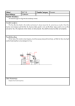
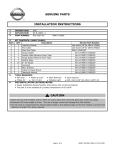
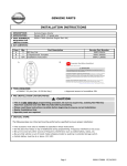
GENUINE PARTS
INSTALLATION INSTRUCTIONS
1.
2.
3.
4.
Item
A
A'
B
C
DESCRIPTION: Fog Lamp Kit
APPLICATION: Maxima (2010)
PART NUMBER: 999F1 MV000 - Sedan w/Auto Headlamps
999F1 MV001 - Sedan w/out Auto Headlamps
KIT CONTENTS:
QTY
1
1
1
1
Combi
Combi
Sedan
Sedan
Description
Sw w/ Auto Headlamps
Sw w/o Auto Headlamps
RH foglamp assembly
LH foglamp assembly
Application
w/Auto Headlamps
w/out Auto Headlamps
Common
Common
A
5.
6.
TOOLS REQUIRED:
● Flat tip screwdriver
● Phillips screwdriver
● 10mm wrench
Service Part Number
25560 9N00A
25560 9N00D
26150 9N00A
26155 9N00A
B
C
● Ratchet
● 10mm socket
● Socket extension
● Torque Bit
● Optional 10mm ratcheting box wrench
PRE-INSTALLATION CAUTIONS/NOTES:
● Dealer Installation Recommended. Instructions refer to Service Manual.
Page 1 of 5
999F1 MV001II A REV
DTH 03/31/2010
INSTALLATION INSTRUCTIONS - Fog Lamp Kit
7.
INSTALLATION PROCEDURE:
Philips
Screws
Philips
Screws
1) Remove engine under cover.
a) Use care when removing the retaining
clips (B) and bolts (A).
(Fig. 1 and Fig. 2)
Note: There may be clips at positions A
instead of bolts.
2) LH/RH - Remove fog lamp covers.
(Fig. 3)
a) Use a Philips screwdriver to let loose
the front of the LH/RH wheel wells.
b) Lower the front wheel well to get
better access to the fog lamp area.
c) Remove the 10mm bolt from
each side (re-use screws).
3) Locate and untape the fog lamp wiring
harness connections (Driver's side)
(Fig. 4)
Tech Note:
Driver's side connector is near the
horn.
Page 2 of 5
999F1 MV001II A REV
DTH 03/31/2010
INSTALLATION INSTRUCTIONS - Fog Lamp Kit
4) Locate and untape the fog lamp wiring
harness connectors (passenger's side).
(Fig. 5)
Tech Note:
Passenger's side connector is located
near the washer fluid reservoir.
5) LH/RH - Install fog lamp provided with kit.
a) Separate the fog lamp from the housing
by removing (2) Torque screws.
b) Using a 10mm wrench, install (2) bolts
through the bracket to the fascia.
One on the side and one on top.
c) Place the fog lamp in the housing and
secure it with the (2) Torque screws
removed earlier.
d) Do this for both sides.
6) Finish install
a) Connect the wire harness to each fog
light by pressing the connector into the
back of each lamp.
b) Install engine under cover and retaining
clips (B) and 10mm bolts (A).
(Fig. 7 and Fig. 8)
c) Secure the front of each wheel well.
Note: Fasteners at location(s) A maybe push in clips similar to B.
Page 3 of 5
999F1 MV001II A REV
DTH 03/31/2010
INSTALLATION INSTRUCTIONS - Fog Lamp Kit
7)
Unlock steering wheel.
8)
Disconnect the negative battery cable, then wait at least 3 minutes.
CAUTION
● Before servicing, disconnect both battery terminals and wait at least 3 minutes.
● Do not use air tools or electric tools for servicing.
● After the work is completed, make sure no system malfunction is detected by air bag warning
lamp.
● In case a malfunction is detected by the air bag warning lamp, reset with the self-diagnosis
function and delete the memory with CONSULT-III
● If a malfunction is still detected after the above operation, perform self-diagnosis to repair
malfunctions. Refer to Service Manual.
Remove upper steering column cover.
9)
a) Rotate steering wheel counterclockwise
to access LH screw (A) and remove.
(Fig. 9)
10) Rotate steering wheel clockwise to access
RH screw (A) and remove.
(Fig. 10)
11) Remove lower steering column cover screw
(B) located under the steering column and
remove upper and lower cover.
(Fig. 11)
Page 4 of 5
999F1 MV001II A REV
DTH 03/31/2010
INSTALLATION INSTRUCTIONS - Fog Lamp Kit
12) Remove 2 screws from the combination
switch and pull upwards for electrical
connection. Disconnect electrical connector
from combination switch by prying release
tab and pulling up on the combination
switch.
(Fig. 12)
13) Remove combination switch by lifting up
and out of steering column.
14) Install kit supplied combination switch using original mounting screws and reconnect wiring.
Connector should 'Click'.
15) Install the steering column upper and lower covers using the original screws.
16) Check all screws are in place and secure.
17) Connect the negative battery cable.
8.
FUNCTIONALITY TEST PROCEDURE:
1) Turn ignition switch ON.
2) Turn headlamp and fog lamp switches ON.
3) Verify headlamps and fog lamps are illuminated.
4) Turn headlamp switch OFF (leaving fog lamp switch ON).
5) Verify both headlamp and fog lamps turn off.
6) Verify turn signal, wiper, washer and high beam functionality.
Page 5 of 5
999F1 MV001II A REV
DTH 03/31/2010