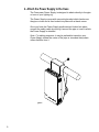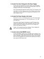
1
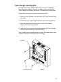
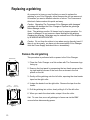
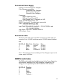
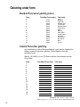
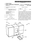
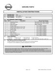
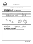
User Manual
4 Inch Color Changer
7 Inch Color Changer
Power Supply
Software version: FR22, FR23
Manual revision: 2
CONTENTS
Introduction ................................................................. 3
The Forerunner System.............................................. 4
Using The Forerunner ................................................ 5
The Forerunner components ...................................... 6
Color Changer ....................................................... 6
Gelstring ................................................................ 6
Power Supply ........................................................ 7
Cables ................................................................... 7
Installing The Forerunner ........................................... 8
Mounting and installation accessories...................... 11
Power Supply hanger bracket ............................. 11
Color Changer mounting plate ............................ 12
Replacing a gelstring ................................................ 13
Specifications............................................................ 15
Parts list .................................................................... 17
Warranty information ................................................ 18
Gelstring order form.................................................. 19
2
Introduction
The Forerunner system is a scrolling Color Changer, in 4-inch and
7-inch models, and Power Supply offering ease of setup and use. Its
16-color capacity and DMX compatibility affords the designer economy
and versatility, particularly when budget and space are limited. The
lightweight Color Changers slide easily into the gel frame holder of the
light fixture and the compact, 16-Color Changer Power Supply attaches
easily to the truss of the lighting rig.
This manual gives step-by-step instructions for preparation, setup and
operation of The Forerunner Color Changer and Power Supply.
3
The Forerunner System
The Forerunner System consists of one or more Color Changers and a
remote Power Supply which can power up to 16 Color Changers. The
DMX512 control signal from the lighting board is connected to the
Power Supply and can continue onto more Forerunner Power Supplies
or other DMX-controlled devices. The Power Supply sends both power
and control signal on a single cable eliminating the need for a separate
power cable for each Color Changer.
Caution: The Forerunner System is not compatible with The Coloram
System. Do not connect Coloram Color Changers to Forerunner Power
Supplies, or Forerunner Color Changers to Coloram Power Supplies.
Damage from such action will not be covered by the Forerunner or
Coloram warranties.
The Forerunner Power Supply
The Forerunner Color Changer
ADJ
ADJ
UST
GEL
LOA
D GEL
ADJ
UST
GEL
LOA
D GEL
To additional
Forerunner
Color Changers
AC Power
Buffered
DMX512
UST
ADJ
GEL
LOA
D GEL
UST
GEL
LOA
D GEL
To additional
Forerunner
Color Changers
To additional
Forerunner
Power Supplies
DMX Control console
DMX CONSOLE
DMX512
Figure 1
4
Using The Forerunner
The Forerunner Color Changer sets its frame position according to the
DMX512 level it receives from the control console for the channel it is
set to. The following chart shows the level settings that correspond with
each frame position. The color of each frame position will be
determined by your custom gelstring specification.
Channel
Level
Frame
Position
00
07
14
21
28
34
42
48
55
61
68
75
80
88
94
FL
Frame 1
Frame 2
Frame 3
Frame 4
Frame 5
Frame 6
Frame 7
Frame 8
Frame 9
Frame 10
Frame 11
Frame 12
Frame 13
Frame 14
Frame 15
Frame 16
If you send a channel level that is between the values shown, you can
create split frame effects. For example, if you send a level of 51, the
Color Changer positions the gelstring halfway between frame 8 and
frame 9 creating a blend of the two colors.
5
The Forerunner Components
Color Changer
The Forerunner Color Changer works with a 16-frame gelstring. The
position of the gelstring is controlled by DMX signal distributed from the
Power Supply. The Color Changer is powered by 24 volts DC from the
Power Supply. The control signal and DC power are both supplied in
the one cable connecting the Color Changer to the Power Supply.
ADJUST GEL
LOAD GEL
ADJUST GEL
4 Inch Forerunner
LOAD GEL
7 Inch Forerunner
Figure 2
Gelstring
The gelstring is a series of 16 precisely-cut, colored gel frames joined
together, side by side, to create a sequence of colors. Two additional
gels at each end of the gelstring are called the leader and the trailer
and are five inches wide to allow for proper attachment to the rollers.
If you need to replace a gelstring in your Color Changer, detailed steps
for this procedure are on page 13.
Trailer
Frame 16
Frame 15
Frame 2
Frame 1
Leader
Figure 3
6
Power Supply
The Power Supply has two Color Changer outputs and provides each
Color Changer with DMX signal and 24 volts DC. The Power Supply
features a DMX bypass relay to pass the DMX signal to the DMX output
connector in the event of AC power loss. The Power Supply
automatically accommodates 85 - 132 VAC (50/60 Hz) or 170 - 264
VAC (50/60 Hz). AC power is indicated by a red LED which can be
viewed from the stage.
Figure 4
Cables
The Forerunner cable connects each of the two Power Supply outputs
to a daisy chain of up to eight Forerunner Color Changers and provides
the Color Changers with power and control signal. The Forerunner
cable uses 4-pin XLR connectors on either end and consists of two -14
AWG conductors and a 22 AWG twisted, shielded pair.
Note: The cable used in the Forerunner System is the same cable
which is used in the Coloram System and may be referred to as either
Coloram cable or Forerunner cable.
7
Installing The Forerunner
To get your Forerunner System up and running, follow these hookup
and checkout procedures.
1. Set the DMX512 Color Changer channels
Each Color Changer is assigned an individual DMX address to which it
will respond from the lighting console. The addresses are set via the
three rotary switches located on the back of each Color Changer. Valid
DMX addresses are 001 - 512.
2. Attach the Color Changer to the lamp
Slide the Color Changer’s mounting bracket into the gel frame holder of
your lamp and lock the gel frame retention clip (if available).
If the mounting plate installed on your Color Changer doesn’t fit the
fixture, you may replace it with a differently sized plate. See page 11 for
information on changing mounting plates.
The mounting plate allows you to position the Color Changer with the
gelstring rolling either horizontally or vertically. However, Forerunner
operates most effectively with the fan blowing air vertically (as hot air
naturally rises).
3. Attach the safety cable
A safety cable is attached to the back, right hand side of the Color
Changer. Run this cable around the pipe or truss from which you hang
the light fixture and clip it to itself (fig. 5).
8
4. Attach the Power Supply to the truss
The Forerunner Power Supply is designed to attach directly to the pipe
or truss of your lighting rig.
The Power Supply comes with a mounting bracket which hooks over
the pipe or truss and is then locked into place with a thumb screw.
Once you have the Power Supply positioned and locked into place,
connect the safety cable by running it around the pipe or truss to which
the Power Supply is attached.
Note: For cabling purposes, it may be preferable to position your
Power Supply toward the center of the pipe or truss and daisy chain
either direction from it.
igure 5
9
5. Connect the Color Changers to the Power Supply
Connect the Color Changers to the Power Supply using the supplied
4-pin power/signal cable. The connectors are on the back of the Color
Changers and the front of the Power Supply.
Note: Both power and signal are supplied to the Color Changers on the
same cable. The Power Supply has two Color Changer outputs. Each
output will control up to eight Color Changers with a maximum of 350
feet of cable per output.
6. Connect the Power Supply to AC power
Plug the AC cord into a non-dimmed power circuit. The power supply
automatically accommodates 85 - 132 VAC (50/60 Hz) or 170 - 264
VAC (50/60 Hz).
Power at the Power Supply is indicated by a red LED which can be
viewed from the stage. Power is also indicated by a red LED on the
bottom of each Color Changer. All connected Color Changers will
position their gelstrings to frame 1.
Caution: Do not power the unit from a dimmer. Severe damage will
result, and is not covered by product warranty.
7. Connect and set the DMX512 source
Connect the DMX512 signal source to the DMX input connector on the
front of the Power Supply using standard DMX cable. Valid DMX signal
will be indicated by a green LED on the bottom of each Color Changer.
Also, the Color Changers will now position their gelstrings according to
their respective DMX signal levels.
10
Mounting and installation accessories
The components of your Forerunner System may require the
installation of additional mounting accessories or the replacement of
others. Some of these accessories, such as the Power Supply hanger
bracket and your choice of one Color Changer mounting plate, are
supplied while other accessories, such as additional mounting plates,
may need to be purchased separately. The following sections describe
the procedures for installation and replacement of these accessories
Power Supply hanger bracket
The Forerunner Power Supply is shipped with a hanger bracket to allow
pipe or truss mounting. The hanger bracket will need to be installed
prior to The Forerunner System installation.
Follow these steps to install the hanger bracket.
1. Disconnect AC power from the Power Supply.
2. Place the Power Supply upside down on a flat surface.
3. Position the bracket as shown below.
4. Attach the bracket using a 3/16" Allen wrench and the supplied
screws.
Note: Use the supplied thumb screw to clamp the hanger bracket to the
desired pipe or truss.
Figure 6
11
Color Changer mounting plate
The Forerunner Color Changer ships with your choice of available
mounting plates installed. It may be necessary, when mounting the
Color Changer on different light fixtures, to replace the mounting plate.
Follow these instructions to replace the mounting plate.
1. Place the Color Changer on a flat surface, with The Forerunner logo
face down.
2. Unscrew the four screws which hold the current mounting plate on.
3. Place the replacement mounting plate on the Color Changer,
aligning the screw holes properly.
4. Fasten the four corners of the mounting plate to the Color Changer
using the same screws you removed in step 2.
Note: Always use the supplied screws, as they are treated with an antivibration compound to keep them from loosening.
ounting plate
Mounting plate screws
Figure 7
12
Replacing a gelstring
At some point in time you may find that you need to replace the
gelstring in your Color Changer, either because the old one wears out,
or because you want a different selection of colors. The Forerunner’s
AutoloadTM feature makes this quick and easy.
Caution: Operating The Forerunner Color Changers with damaged
gelstrings will damage the Color Changers. Replace the gelstrings
before damage occurs.
Note: The gelstring must be 16 frames long for proper operation. If a
frame is damaged, do not remove a frame and splice the gelstring.
Replace the gelstring. Gelstrings may be ordered from Color Express
by WYBRON INCORPORATED.
Caution: Do not force the rollers to turn when moving them by hand. If
they do not turn easily, you have not disconnected the Color Changer
from the Power Supply and should do so immediately.
Remove the old gelstring
This procedure is performed with no power to the Color Changer.
Thumb screws
1. Place the Color Changer on a flat surface with The Forerunner logo
facing up.
2. Remove the front panel by unscrewing the two thumb screws at the
top right and left corners of the front door as shown in the first
picture on the left.
ADJUST GEL LOAD GEL
Figure 8
Left roller
(trailer/ frame 16)
3. Gently roll the gelstring onto the left roller, exposing the clear leader
taped on the right roller.
Right roller
(Leader/ frame 1)
4. Untape the leader from the right roller. Remove the tape from the
leader.
5. Roll the gelstring into a tube, slowly rolling it off of the left roller.
6. When you reach the clear trailer, untape it from the roller.
Hint: To save time, move all gelstrings to frame one via the DMX
source before disconnecting power.
ADJUST GELLOAD GEL
Figure 9
13
Install the new gelstring
Note: Use gaffer’s tape to attach the gelstrings to the rollers. Do not
use duct tape or masking tape.
1. Apply power to the Color Changer.
2. Press the recessed "Load Gel" button located in the lower right
hand corner of the Color Changer. The rollers will rotate to the
trailer load position. The rapidly flashing "DMX" LED indicates the
rollers are
either moving toward the trailer load position or are at the trailer
load position.
3. Put a strip of gaffer’s tape on the edge of the gelstring trailer.
Holding the trailer, let the rest of the roll hang off the right side of the
Color Changer.
Adjust Gel
Figure 10
Load Gel
4. Center the edge of the trailer between the two ends of the left roller
as shown to the left. Tape the trailer along the top of the roller as
shown.
5. Hold the gelstring loosely in your right hand and press the "Load
Gel" button again. The rollers will rotate to the leader load position.
This will wind the gelstring onto the left roller. The "DMX" LED will
flash slowly to indicate the rollers are either moving toward the
leader load position or are at the leader load position.
Gaffer’s tape
6. Turn the "Adjust Gel" trim pot to bring the leader end of the gelstring
to the top center of the right roller. Gel material of different thickness
will cause variation in the leader end position. This is normal.
7. Put a strip of gaffer’s tape on the gelstring leader.
8. While holding the end of the gelstring, turn the spring roller 3.5 turns
toward the drive roller. The sticker at the bottom end of the roller
has a black line on it to help you judge the number of turns
Trailer
Figure 11
Frame 16
9. Tape the gelstring to the spring roller.
10. Press the "Load Gel" button once again. The gelstring will now
move to the first frame if no DMX signal is present or to the
commanded DMX level if it is.
11. Replace the front panel and tighten the thumb screws securely.
Note: As the gelstring becomes worn, you may find it necessary to
adjust the position of frame 1. This is normal and is done by turning the
"Adjust Gel" trim pot.
14
Specifications
Forerunner Color Changer
DMX termination: Not required
End to end speed: 5 seconds
Fan: Single speed - normal
Fuse: Solid state internal auto reset
Gelstring: 16 colors
Individual DMX address: 001 - 512
Fixture compatibility (with optional mounting plates):
4 Inch Forerunner
Source Four
Shakespeare 600
Other fixtures with 6.25" gel frames
7 Inch Forerunner
Source Four
Shakespeare 600
Other fixtures with 6.25" gel frames
Source Four PAR
PAR 64
Full size ellipsoidals
LED Indicators: Power and DMX512 signal
Power supply compatibility:
Forerunner Power Supply
Rainbow Power Supply
ChromaQ Power Supply
Weight:
4 inch - 3.0 lbs./1.36 kg
7 inch - 3.38 lbs./1.53 kg
Forerunner gelstring
4 Inch Forerunner:
16 frames plus leader and trailer
Working length: 128"
Overall length: 138"
Frame width: 8"
Frame height: 6 1/8"
Leader: 5"
Trailer: 5"
7 Inch Forerunner:
16 frames plus leader and trailer
Working length: 160"
Overall length: 170"
Frame width: 10"
Frame height: 7 1/16"
Leader: 5"
Trailer: 5"
15
Forerunner Power Supply
Capacity: 16 Forerunner Color Changers
Color Changer compatibility:
Forerunner Color Changers
Rainbow Color Changers
ChromaQ Color Changers
Connectors:
DMX in: Male 5-pin XLR
DMX out: Female 5-pin XLR
Color Changer out x 2: Female 4-pin XLR
Power loss DMX bypass relay: Yes
DMX512 termination: Terminated and regenerated
Fuse: 2 amp slow blow at 115 VAC
1 amp slow blow at 230 VAC
Input Power: Automatically accepts 85 - 132 VAC 50/60 Hz and
170 - 264 VAC 50/60Hz
Input Signal: 1990 USITT standard DMX512
LED indicator: Power
Forerunner cable
The Forerunner cable uses 4-pin XLR connectors on either end and
consists of two -14 AWG conductors and a 22 AWG twisted, shielded
pair.
XLR Pin #
1
2
3
4
Wire Color
White
Green
Red
Black
Function
Ground
Data Data +
24 Volts DC
Size
14 AWG
22 AWG
22 AWG
14 AWG
Note: The maximum amount of cable per Color Changer output on the
power supply is 350 feet.
DMX512 control cable
The DMX control cable from the lighting board to the Power Supply is a
five conductor cable with 5-pin XLR connectors on each end. The
wiring pin out is specified by the USITT DMX512/ 1990 standard.
XLR Pin #
1
2
3
4
5
Function
Common
Data Data +
Talkback Talkback +
16
Parts list
To order any of the following items, contact your authorized WYBRON dealer.
Forerunner Color Changers and Power Supplies
4540 ........................4 Inch Forerunner Color Changer
7140 ........................7 Inch Forerunner Color Changer
7150 ........................The Forerunner Power Supply
4549-16...................4 Inch Forerunner gelstring
7149-16...................7 Inch Forerunner gelstring
715-08-01................User Manual
Forerunner mounting and installation accessories
715-01-03P .............Power Supply hanger bracket
SCRWC252075 ......Wing screw for Power Supply hanger bracket to pipe
SCRSC2520037 .....Socket cap screw for hanger bracket to Power Supply
452-01-03P .............6.25"/158.75mm mounting plate for 4 inch Color Changer
452-03-04................6.25"/158.75mm mounting plate for 7 inch Color Changer
703-01-03P .............7.5"/190.5mm mounting plate for 7 inch Color Changer
703-01-05P .............10"/254mm mounting plate for 7 inch Color Changer
SCRPH832037 .......Pan head screws for mounting plate to Color Changer
Forerunner System cable
7042-3.....................3’ power/signal cable
7042-5.....................5’ power/signal cable
7042-10...................10’ power/signal cable
7042-15...................15’ power/signal cable
7042-25...................25’ power/signal cable
7042-50...................50’ power/signal cable
7042-75...................75’ power/signal cable
7042-100.................100’ power/signal cable
17
Warranty information
WYBRON, INC. warrants to the original owner or retail customer that
for a period of one year from date of delivery of a portable system or
energization of a permanently installed system (up to a maximum of 18
months from delivery) its products will be free from defects in materials
and workmanship under normal use and service.
Warranty does not cover any product or part of a product subject to
accident, negligence, alteration, abuse, misuse or any accessories or
parts not supplied by WYBRON, INC.. Warranty does not cover
"consumable" parts such as fuses, lamps, or color media. WYBRON,
INC.’s warranty does not extend to items not manufactured by us.
Freight terms on warranty repairs are FOB WYBRON, INC. factory or
designated repair facility. Collect shipments or freight allowances will
not be accepted.
WYBRON, INC.’s sole responsibility under this warranty shall be to
repair or replace at WYBRON, INC.’s option such parts as shall be
determined to be defected on WYBRON, INC.’s inspection. WYBRON,
INC. will not assume any responsibility for any labor expended or
materials used to repair any equipment without WYBRON, INC.’s prior
written authorization . WYBRON, INC. shall not be responsible for any
incidental, general or consequential damages to property, damages for
loss of use, time, profits or income, or any other charges.
The owner’s obligations during the warranty period under this warranty
are to notify WYBRON, INC. at WYBRON, INC.’s address within one
week of any suspected defect, and return the goods prepaid to
WYBRON, INC. at their factory or authorized service center.
This warranty is contingent on the customer’s full and timely compliance
with the terms of payment set forth in said purchase order. This
warranty is expressly in lieu of any and all other warranties expressed
or implied including the warranties of merchantability and fitness for a
particular purpose and of other obligations and liabilities on our part.
The owner acknowledges that no other representations were made to
him or relied upon him with respect to the quality and function of the
goods sold.
This written warranty is intended as a complete and exclusive
statement of the terms thereof. Prior dealings or trade usage shall not
be relevant to modify, explain or vary this warranty. Acceptance of, or
acquiescing in, a course of performance under this warranty shall not
modify the meaning of this agreement even though either party has
knowledge of the performance and a chance to object.
18
Gelstring order form
Standard Forerunner gelstring colors
Frame
1
2
3
4
5
6
7
8
9
10
11
12
13
14
15
16
Filter Mfgr./Color number
---G140
G155
G250
G290
G325
G345
G370
G450
G540
G650
G685
G790
G810
G850
G995
Color name
Clear
Magenta
Light Pink
Medium Red
Fire Orange
Bastard Amber
Deep Amber
Spice
Saffron
Pale Green
Grass Green
Pistachio
Electric Blue
Moon Blue
Blue
Orchid
Custom Forerunner gelstring
Any combination of color filter manufacturer’s gels can be combined to
create a custom Forerunner gelstring. Please specify using the
following format.
Specify: (G) GAM, (L) Lee, (R) Rosco with the color number and the
color name.
Frame
1
2
3
4
5
6
7
8
9
10
11
12
13
14
15
16
Filter Mfgr./Color number
Color name
WYBRON, INC. - TEL 719-548-9774 - FAX 719-548-0432
Email: [email protected] - Visit us on the World Wide Web at http://www.wybron.com
19
WYBRON, INC. - TEL 719-548-9774 - FAX 719-548-0432
Email: [email protected] - Visit us on the World Wide Web at http://www.wybron.com