1
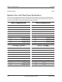
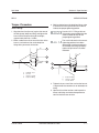
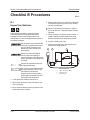
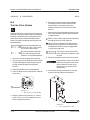
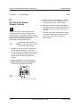
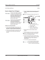
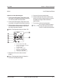
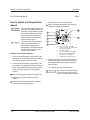
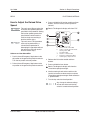
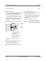
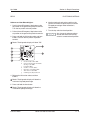
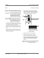
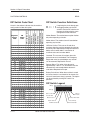
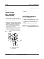
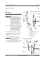
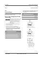
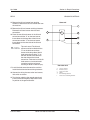
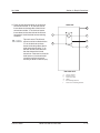
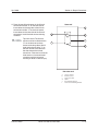
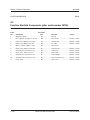
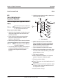
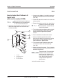
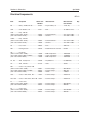
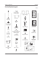
April 2003
Section 4 • Repair Procedures
FUNCTION MANIFOLD
REV B
6-4
Valve Coils
How to Test a Coil Diode
How to Test a Coil
A properly functioning coil provides an
electromotive force which operates the solenoid
valve. Critical to normal operation is continuity
within the coil that provides this force field.
Genie incorporates spike suppressing diodes in all
of its coils. Properly functioning coil diodes protect
the electrical circuit by suppressing voltage spikes.
Voltage spikes naturally occur within a function
circuit following the interruption of electrical current
to a coil. Faulty diodes can fail to protect the
electrical system, resulting in a tripped circuit
breaker or component damage.
Electrocution hazard. Contact with
electrically charged circuits could
result in death or serious injury.
Remove all rings, watches and
other jewelry.
1 Tag and disconnect the wire harness from the
coil to be tested.
Electrocution hazard. Contact with
electrically charged circuits could
result in death or serious injury.
Remove all rings, watches and
other jewelry.
1 Test the coil for resistance. See 6-4 How to
Test a Coil.
2 Test the coil resistance.
Result: The resistance should be within
specification, plus or minus 30%.
Result: If the resistance is not within
specification, plus or minus 30%, replace the
coil.
Valve Coil Resistance Specifications
Description
Specification
Solenoid valve, 3 position 4 way
25 to 27 Ω
20V DC with diode (schematic item AF and BI)
Solenoid valve, 2 position 4 way
20V DC with diode (schematic item AG)
18 to 20 Ω
Solenoid valve, N.O. poppet
20V DC with diode (schematic item AH)
25 to 27 Ω
Solenoid valve, 3 position 4 way
18 to 20 Ω
20V DC with diode (schematic item AI and BJ)
Solenoid valve, 2 position 4 way
20V DC with diode (schematic item BG)
4 - 66
18 to 20 Ω
Genie GS-1530 and GS-1930
Part No. 72876