1
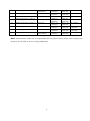
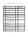
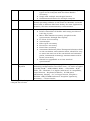
Institute of Nano Science and Technology Habitat Centre, Sector 64, Phase X, Mohali -160062, Punjab, India Ph: +91-172-2210073/75; Fax: +91-172-2211074; E-mail ID: [email protected] NOTICE INVITING TENDER INST invites tender from the reputed manufacturers or their authorized dealers so as to reach this office on or before scheduled date and time for the instrument, as per specifications given in the Annexure attached to the Tender form. All offers should be made in English and should be written in both figures and words. Tender forms can be downloaded from the website (www.inst.ac.in) of the Institute. The bidders are requested to read the tender document carefully and ensure compliance with all specifications/instructions herein. Non-compliance with specifications/instructions in this document may disqualify the bidders from the tender exercise. The Director reserves the right to select the item (in single or multiple units) or to reject any or all quotation(s) without assigning any reason. Incomplete tenders, amendments and additions to tender after opening or late tenders are liable to be ignored and rejected. S.No. Ref. No. Instrument 1. INST/equip/2013-14/M-01 Fluorimeter 2. INST/equip/2013-14/M02a Microfluidics: Optical Microscope Camera 3. INST/equip/2013-14/M02b INST/equip/2013-14/M02c INST/equip/2013-14/M02d INST/equip/2013-14/M-03 4. INST/equip/2013-14/M-04 UV-VIS 5. INST/equip/2013-14/M-05 FTIR 6. INST/equip/2013-14/M-06 TG-DTA 7. INST/equip/2013-14/M-07 DSC 8. INST/equip/2013-14/M-08 9. INST/equip/2013-14/M-09 Particle size Analyser Surface profiler Tender submission 18-11-13 1200 hrs 18-11-13 1200 hrs Tender opening 18-11-13 1500 hrs 18-11-13 1500 hrs EMD Rs 20,000/Rs 50,000/Rs 10,000/- Plasma Cleaner Rs 15,000/- Syringe pump Rs 15,000/- UV-VIS-NIR 1 18-11-13 1200 hrs 18-11-13 1200 hrs 19-11-13 1200 hrs 19-11-13 1200 hrs 19-11-13 1200 hrs 19-11-13 1200 hrs 19-11-13 1200 hrs 18-11-13 1500 hrs 18-11-13 1500 hrs 19-11-13 1500 hrs 19-11-13 1500 hrs 19-11-13 1500 hrs 19-11-13 1500 hrs 19-11-13 1500 hrs Rs 70,000/Rs 20,000/Rs 75,000/Rs 40,000/Rs 40,000/Rs 80,000/Rs 50,000/- 10. INST/equip/2013-14/M-10 Electrochemical workstation Biosafety cabinet 11. INST/equip/2013-14/M-11 12. PCR 13. I NST/equip/2013-14/M-12 INST/equip/2013-14/M-13 14. INST/equip/2013-14/M-14 Glove box 15. INST/equip/2013-14/M-15 SEM 16. INST/equip/2013-14/M-16 Confocal Raman 17. INST/equip/2013-14/M-17 Digital DC Source Meter Gel doc 20-11-13 1200 hrs 20-11-13 1200 hrs 20-11-13 1200 hrs 20-11-13 1200 hrs 20-11-13 1200 hrs 21-11-13 1200 hrs 21-11-13 1200 hrs 21-11-13 1200 hrs 20-11-13 1500 hrs 20-11-13 1500 hrs 20-11-13 1500 hrs 20-11-13 1500 hrs 20-11-13 1500 hrs 21-11-13 1500 hrs 21-11-13 1500 hrs 21-11-13 1500 hrs Rs 50,000/Rs 15,000/Rs 20,000/Rs 10,000/Rs 25,000/Rs 2,00,000/Rs 3,00,000/Rs 10,000/- Note: The Institute shall not be responsible for any postal delay about non-receipt/non delivery of the bids or due to wrong addressee. 2 TERMS AND CONDITIONS Important Conditions of the tender to be abide by the tenderer 1. Due date: The tender has to be submitted before the due date. The offers received after the due date and time will not be considered. 2. Preparation Bids: The offer/bid should be submitted in two bid systems (i.e.) Technical bid and Financial bid. The technical bid should consist of all technical details along with commercial terms and conditions. Financial bid should indicate item wise price for the items mentioned in the technical bid. The Technical bid and the financial bid should be put in separate covers and sealed. Both the sealed covers should be put into a bigger cover along with letter of EMD and to be sealed. The tender number and details should be superscripted on the left side of the outer cover. The Quotations should be valid for 120 days from the due date. The Quotations duly sealed and super scribed on the envelope with the reference No. and due date, should be addressed to “The Director, Institute of Nano Science and Technology, Habitat Centre, Sector 64, Phase –X, Mohali, 160062, Punjab, India” so as to reach on or before the due date. 3. Delivery of the tender: The tender shall be sent to the addressee mentioned in the para 2 above either by post or by courier so as to reach our office before the due date specified in our Schedule. The offer/bid can also be dropped in the tender box on or before the due date specified in the schedule. The tender box is kept in Foyer area of INST. The institute will not take any responsibility for any postal delay. 4. Opening of the tender: The offer/bid will be opened by a committee duly constituted for this purpose. The technical bid will be opened first and it will be examined by a technical committee which will decide the suitability as per our specification and requirement. The financial offer/bid will be opened only for the offer/bid which technically meets all our requirements as per the specification. The bidders if interested may participate on the tender opening Date and Time. The bidder should produce authorization letter from their company to participate in the tender opening. Only one representative will be allowed to participate in the tender opening. 5. Acceptance/Rejection of bids: The Director reserves the right to reject any or all offers without assigning any reason. 3 6. Pre-qualification criteria: (i) Bidders should be the manufacturer/authorized dealer. Letter of Authorization from original equipment manufacturer (OEM) on the same and specific to the tender should be enclosed. (ii) An undertaking from the OEM is required stating that they would facilitate the bidder on a regular basis with technology/product updates and extend support for the warranty as well. (iii) OEM should be internationally reputed Branded Company. (iv) Non-compliance of tender terms, non-submission of required documents, lack of clarity of the specifications, contradiction between bidder specification and supporting documents etc. may lead to rejection of the bid. (v) Either the Indian agent on behalf of the Principal/OEM or Principal/OEM itself can bid but both cannot bid simultaneously for the same item/product in the same tender. If an agent submits bid on behalf of the Principal/OEM, the same agent shall not submit a bid on behalf of another Principal/OEM in the same tender for the same item/product. 7. EMD: The tenderer should submit an EMD amount along with the tender by way of Demand Draft/BG/Banker’s Pay Order drawn in favour of “Institute of Nano Science and Technology, Mohali” and payable at Chandigarh/Mohali from any nationalized bank valid for six months. The Technical Bid without EMD would be considered as UNRESPONSIVE and will not be accepted. The EMD will be returned without any interest to the unsuccessful bidders immediately after the award of contract. 8. Refund of EMD: The EMD will be returned to unsuccessful Tenderer only after the Tenders are finalized. In case of successful Tenderer, it will be retained till the successful and complete installation of the equipment. 9. Performance Security: The supplier shall be required to submit the performance security in the form of irrevocable bank guarantee issued by any Indian Nationalized Bank for an amount of which is equal to the 10% of FOB value within 21 days from the date of receipt of the purchase order and should be kept valid for a period of 60 days beyond the date of completion of warranty period. 10. Force Majeure: The Supplier shall not be liable for forfeiture of its performance security, liquidated damages or termination for default, if and to the extent that, it’s delay in performance or other failure to perform its obligations under the Contract is the result of an event of Force Majeure. 4 (i) For purposes of this Clause, "Force Majeure" means an event beyond the control of the Supplier and not involving the Supplier's fault or negligence and not foreseeable. Such events may include, but are not limited to, acts of the Purchaser either in its sovereign or contractual capacity, wars or revolutions, fires, floods, epidemics, quarantine restrictions and freight embargoes. (ii) If a Force Majeure situation arises, the Supplier shall promptly notify the Purchaser in writing of such conditions and the cause thereof. Unless otherwise directed by the Purchaser in writing, the Supplier shall continue to perform its obligations under the Contract as far as is reasonably practical, and shall seek all reasonable alternative means for performance not prevented by the Force Majeure event. 11. Risk Purchase Clause: In event of failure of supply of the item/equipment within the stipulated delivery schedule, the purchaser has all the right to purchase the item/equipment from the other source on the total risk of the supplier under risk purchase clause. 12. Packing Instructions: Each package will be marked on three sides with proper paint/indelible ink, the following: (i) Item Nomenclature (ii) Order/Contract No. (iii) Country of Origin of Goods (iv) Supplier’s Name and Address (v) Consignee details (vi) Packing list reference number 13. Delivery and Documents: Delivery of the goods should be made within a maximum of 08 to 12 weeks from the date of placement of purchase order and the opening of LC. Within 24 hours of shipment, the supplier shall notify the purchaser and the insurance company by cable/telex/fax/email the full details of the shipment including contract number, railway receipt number/ AAP etc. and date, description of goods, quantity, name of the consignee, invoice etc. The supplier shall mail the following documents to the purchaser with a copy to the insurance company: (i) 4 Copies of the Supplier invoice showing contract number, goods' description, quantity (ii) unit price, total amount; (iii) Acknowledgment of receipt of goods from the consignee(s) by the transporter; 5 Insurance Certificate if applicable; Manufacturer's/Supplier's warranty certificate; Inspection Certificate issued by the nominated inspection agency, if any, and the (vii) Supplier’s factory inspection report; and (viii) Certificate of Origin. (ix) Two copies of the packing list identifying the contents of each package. (x) The above documents should be received by the Purchaser before arrival of the (iv) (v) (vi) Goods (except where the Goods have been delivered directly to the Consignee with all documents) and, if not received, the Supplier will be responsible for any consequent expenses 14. Delayed delivery: If the delivery is not made within the due date for any reason, the Director will have the right to impose penalty @1% per week and the maximum deduction would be 10% of the contract value / price. 15. Prices: The price should be quoted in net per unit (after breakup) and must include all packing and delivery charges. The offer/bid should be exclusive of taxes and duties, which will be paid by the purchaser as applicable. However the percentage of taxes & duties shall be clearly indicated. The price should be quoted without custom duty and excise duty, since INST is exempted from payment of Excise Duty and is eligible for concessional rate of custom duty. Necessary certificate will be issued on demand. In case of import supply the price should be quoted on FOB Basis. Also please indicate CIF charges separately upto New Delhi indicating the mode of shipment. INST will make necessary arrangements for the clearance of imported goods at the Airport/Seaport. Hence the price should not include the above charges. 16. Notices: For the purpose of all notices, the following shall be the address of the Purchaser and Supplier. Any notice given by one party to the other pursuant to this contract/order shall be sent to the other party in writing or by cable/telex/FAX/email and confirmed in writing to the other party’s address. A notice shall be effective when delivered or on the notice’s effective date, whichever is later. Purchaser: The Director, Institute of Nano Science and Technology, Habitat Centre, Sector – 64, Phase X, Mohali -160062, Punjab, India 6 Supplier: (To be filled in by the supplier) ............................................................................ ............................................................................ ............................................................................ 17. Resolution of Disputes: The dispute resolution mechanism to be applied pursuant shall be as follows: (i) In case of Dispute or difference arising between the Purchaser and a domestic supplier relating to any matter arising out of or connected with this agreement, such disputes or difference shall be settled in accordance with the Indian Arbitration & Conciliation Act, 1996, the rules there under and any statutory modifications or reenactments thereof shall apply to the arbitration proceedings. The dispute shall be referred to the Director, Institute of Nano Science and Technology (INST) Mohali and if he is unable or unwilling to act, to some other person appointed by him willing to act as such Arbitrator. The award of the arbitrator so appointed shall be final, conclusive and binding on all parties to this order. (ii) In the case of a dispute between the purchaser and a Foreign Supplier, the dispute shall be settled by arbitration in accordance with provision of sub-clause (a) above. But if this is not acceptable to the supplier then the dispute shall be settled in accordance with provisions of UNCITRAL (United Nations Commission on International Trade Law) Arbitration Rules. (iii) The venue of the arbitration shall be the place from where the order is issued. 18. Jurisdiction & Applicable Law: Any legal disputes arising out of any breach of contract pertaining to this tender shall be settled in the court of competent jurisdiction located within Mohali. The Contract shall be interpreted in accordance with the laws of the Union of India and all disputes shall be subject to place of jurisdiction i.e., Mohali (Punjab) INDIA. 19. Defective Equipment: If any of the equipment supplied by the Tenderer is found to be substandard, refurbished, un-merchantable or not in accordance with the description/specification or otherwise faulty, the Director will have the right to reject the equipment or its part. The prices of such equipment shall be refunded by the Tenderer with 18% interest if such payments for such equipment have already 7 been made. All damaged or unapproved goods shall be returned at suppliers cost and risk and the incidental expenses incurred thereon shall be recovered from the supplier. Defective part in equipment, if found before installation and/or during warranty period, shall be replaced within 45 days on receipt of the intimation from this office at the cost and risk of supplier including all other charges. In extreme cases, black-listing of firm can be done on the recommendations of the Director. 20. Right to Use Defective Goods: If after delivery, acceptance and installation and within the guarantee and warranty period, the operation or use of the goods proves to be unsatisfactory, the Purchaser shall have the right to continue to operate or use such goods until rectifications of defects, errors or omissions by repair or by partial or complete replacement is made without interfering with the Purchaser’s operation. 21. Supplier Integrity: The Supplier is responsible for and obliged to conduct all contracted activities in accordance with the Contract using state of the art methods and economic principles and exercising all means available to achieve the performance specified in the contract. 22. User list: Brochure detailing technical specifications and performance, list of industrial and educational establishments where the items enquired have been supplied must be provided. 23. Site Preparation: The supplier shall inform to the Institute about the site preparation, if any, needed for the installation of equipment, immediately after the receipt of the purchase order. The supplier must provide complete details regarding space and all the other infrastructural requirements needed for the equipment, which the Institute should arrange before the arrival of the equipment to ensure its timely installation and smooth operation thereafter. The supplier shall visit the Institute and see the site where the equipment is to be installed and may offer his advice and render assistance to the Institute in the preparation of the site and other pre-installation requirements. 24. Installation & Demonstration: The equipment or machinery has to be installed or commissioned by the successful bidder within 30 days from the date of receipt of the item at INST. In case of any mishappening/damage to equipment and supplies 8 during the carriage of supplies from the origin of equipment to the installation site, the supplier has to replace it with new equipment/supplies immediately at his own risk. Supplier will settle his claim with the insurance company as per his convenience. INST will not be liable to any type of losses in any form. The supplier is also required to do the demonstration of the equipment within one month of the arrival at the INST site of installation, otherwise the penalty clause will be the same as per the supply of materials. 25. Training of Personnel: The supplier shall be required to undertake to provide the technical training to the personnel involved in the use of the equipment at the Institute premises, immediately after completing the installation of the equipment for a minimum period of one week at the supplier’s cost. 26. Manuals and Drawings: (i) Before the goods and equipment are taken over by the Purchaser, the Supplier shall supply operation and maintenance manuals. These shall be in such details as will enable the Purchaser to operate, maintain, adjust and repair all parts of the equipment as stated in the specifications. (ii) The Manuals shall be in the ruling language (English) in such form and numbers as stated in the contract. (iii) Unless and otherwise agreed, the goods/equipment shall not be considered to be completed for the purposes of taking over until such manuals and drawing have been supplied to the Purchaser. 27. Downtime: During the warranty period not more than 5% downtime will be permissible. For every day exceeding permissible downtime, penalty of 1/365 of the 5% FOB value will be imposed. Downtime will be counted from the date and time of the filing of complaint with in the business hours. 28. Spare Parts: The Supplier may be required to provide any or all of the following materials, notifications, and information pertaining to spare parts manufactured or distributed by the Supplier: (i) Such spare parts as the Purchaser may elect to purchase from the Supplier, providing that this election shall not relieve the Supplier of any warranty obligations under the Contract; and (ii) In the event of termination of production of the spare parts: (iii) Advance notification to the Purchaser of the pending termination, in sufficient time to permit the Purchaser to procure needed requirements; and 9 (iv) Following such termination, furnishing at no cost to the Purchaser, the blueprints, drawings and specifications of the spare parts, if requested. Supplier shall carry sufficient inventories to assure ex-stock supply of consumable spares for the Goods, such as gaskets, plugs, washers, belts etc. Other spare parts and components shall be supplied as promptly as possible but in any case within six months of placement of order. 29. Application Specialist: The Tenderer should mention in the Techno-Commercial bid the availability and names of Application Specialist and Service Engineers in the nearest regional office. 30. Shifting: After 3-4 years once our new building is ready, the supplier has to shift and reinstall the instrument free of cost. 31. Insurance: For delivery of goods at the purchaser’s premises, the insurance shall be obtained by the Supplier in an amount equal to 110% of the value of the goods from "warehouse to warehouse" (final destinations) on “All Risks" basis including War Risks and Strikes. The insurance shall be valid for a period of not less than 3 months after installation and commissioning. In case of orders placed on FOB/FCA basis, the purchaser shall arrange Insurance. 32. Warranty: (i) The tender must be quoted with 36 months on-site comprehensive warranty / guarantee which will commence from the date of the satisfactory installation/commissioning of the equipment at the INST against the defect of any manufacturing, workmanship and poor quality of the components. The Supplier shall, in addition, comply with the performance and/or consumption guarantees specified under the contract. If for reasons attributable to the Supplier, these guarantees are not attained in whole or in part, the Supplier shall at its discretion make such changes, modifications, and/or additions to the Goods or any part thereof as may be necessary in order to attain the contractual guarantees specified in the Contract at its own cost and expense and to carry out further performance tests. After the warranty period is over, Annual Maintenance Contract (AMC)/Comprehensive Maintenance Contract (CMC) up to next two years should be started. The AMC/CMC charges will be included in computing the total cost of the equipment. Note: If a different period of warranty has been specified in the ‘Technical Specifications’ then the period mentioned above shall stand modified to that extent. 10 (ii) The Purchaser shall promptly notify the Supplier in writing of any claims arising under this warranty. Upon receipt of such notice, the Supplier shall immediately within 02 days arrange to repair or replace the defective goods or parts thereof free of cost at the ultimate destination. The Supplier shall take over the replaced parts/goods at the time of their replacement. No claim whatsoever shall lie on the Purchaser for the replaced parts/goods thereafter. The period for correction of defects in the warranty period is 02 days. If the supplier having been notified fails to remedy the defects within 02 days, the purchaser may proceed to take such remedial action as may be necessary, at the supplier’s risk and expenses and without prejudice to any other rights, which the purchaser may have against the supplier under the contract. 33. Governing Language: The contract shall be written in English language. English language version of the Contract shall govern its interpretation. All correspondence and other documents pertaining to the Contract, which are exchanged by the parties, shall be written in the same language. 34. Agency Commission: Agency commission if any will be paid to the Indian agent in Rupees on receipt of the equipment and after satisfactory installation. Agency Commission will not be paid in foreign currency under any circumstances. The details should be explicitly shown in Tender even in case of Nil commission. The tenderer should indicate the percentage of agency commission to be paid to the Indian agent. 35. Payment: Payment will be made through irrevocable Letter of Credit (LC). LC will be established in the favour of foreign Supplier after the submission of performance security. LC will be established on the exchange rates as applicable on the date of establishment. (i) For Indigenous supplies, 100% payment shall be made by the Purchaser against delivery, inspection, successful installation, commissioning and acceptance of the equipment at INST in good condition and to the entire satisfaction of the Purchaser and on production of unconditional performance bank guarantee as specified in Clause 9 of tender terms and conditions. (ii) For Imports, LC will be opened for 100% FOB/CIF value. 80% of the LC amount shall be released on presentation of complete and clear shipping documents and 20% of the LC amount shall be released after the installation and demonstration of the equipment at the INST site of installation in faultless working condition for period of 11 60 days from the date of the satisfactory installation and subject to the production of unconditional performance bank guarantee as specified in Clause 9 of tender terms and conditions. (iii) Indian Agency commission (IAC), if any shall be paid after satisfactory installation & commissioning of the goods at the destination at the exchange rate prevailing on the date of negotiation of LC documents, subject to DGS&D registration for restricted items. (iv) All the bank charges within India will be borne by the Institute and outside India will be borne by the Supplier. 36. Termination for Default/Risk Purchase Clause: The Purchaser may, without prejudice to any other remedy for breach of contract, by written notice of default sent to the Supplier, terminate the Contract in whole or part: (i) If the Supplier fails to deliver any or all of the Goods within the period(s) specified in the order, or within any extension thereof granted by the Purchaser; or (ii) If the Supplier fails to perform any other obligation(s) under the Contract. (iii) If the Supplier, in the judgment of the Purchaser has engaged in corrupt or fraudulent practices in competing for or in executing the Contract. For the purpose of this Clause: (a)“Corrupt practice” means the offering, giving, receiving or soliciting of anything of value to influence the action of a public official in the procurement process or in contract execution. (b)“Fraudulent practice” means a misrepresentation of facts in order to influence a procurement process or the execution of a contract to the detriment of the Purchaser, and includes collusive practice among Bidders (prior to or after bid submission) designed to establish bid prices at artificial non-competitive levels and to deprive the Purchaser of the benefits of free and open competition. In the event the Purchaser terminates the Contract in whole or in part, the Purchaser may procure, upon such terms and in such manner, as it deems appropriate, Goods or Services similar to those undelivered, and the Supplier shall be liable to the Purchaser for any excess costs for such similar Goods or Services. However, the Supplier shall continue the performance of the Contract to the extent not terminated. 12 37. Compliancy certificate: This certificate must be provided indicating conformity to the technical specifications. 38. Acknowledgement: It is hereby acknowledged that we have gone through all the conditions mentioned above and we agree to abide by them. SIGNATURE OF TENDERER ALONG WITH SEAL OF THE COMPANY WITH DATE 13 BID PARTICULARS 1. Name of the Supplier : 2. Address of the Supplier : 3. Availability of demonstration of equipment : Yes / No 4. EMD enclosed : Yes / No 5. If Yes, D.D. No._________________ Bank ______________ Amount ________________ 6. Name and address of the Officer/contact person to whom all references shall be made regarding this tender enquiry Name: Address: Phone: Fax: Mobile: Email: Web: 14 Compliance statement for the tender specifications Ref No.: S.No. Check list of documents/Undertakings 1. 2. 3. 4. 5. 6. 7. 8. 9. 10. 11. 12. Yes/No Remarks (give explanation if the answer is No) Is EMD attached? (if applicable) Is the bidder original equipment manufacturer (OEM)/authorised dealer? If authorised dealer, recent dated certificate to this effect from OEM, attached or not? Undertaking from OEM regarding technical support & extended warranty period. Validity of 120 days or not? Undertaking from bidder regarding acceptance of tender terms & conditions Whether list of reputed users (along with telephone numbers of contact persons) for the past three years specific to the instrument attached? Does the instrument comply with all the specifications detailed? Attach a separate sheet showing compliance with the specifications and explanations thereto if the equipment varies from the requested specifications. Whether free Installation, Commissioning and Application Training offered? Whether Three years comprehensive onsite extended warranty offered? Whether Annual maintenance after expiry of comprehensive onsite warranty quoted separately? Whether free of cost shifting of instrument from transit campus to main campus offered? 15 ANNEXURE Ref. No.: INST/Equip/2013-14/M-01 Technical Specifications for Fluorescence Spectrophotometer*: S. No. 1 2 Description Source Monochromator 3 Grating 4 Detectors 5 Spectral bandwidth Wavelength range Wavelength accuracy Wavelength Repeatability Sensitivity 6 7 8 9 10 11 12 13 14 15 Resolution Wavelength scan speed Standard Sample holder Automatic cell changer Quartz Cuvette Measurements mode Technical Specification Xenon steady state lamp 450 W Czerny-Turner or equivalent and double monochromator on the excitation side Excitation: 1200 lines/mm, blazed at ~340 nm. Emission: 1200 lines/mm, blazed at ~500 nm High performance PMT (preferably thermoelectric cooled to minimize dark current) The spectrometer should be equipped with a reference photodiode to monitor excitation lamp intensity fluctuations 1.5 to 10 nm (continuously variable and computer controlled) 240 to 900 nm or better (Xe lamp has no output near 200 nm) ± 1 nm ± 0.1 nm greater than 5000:1 based on 5 nm slits (excitation and emission) and excitation at ~350 nm for water Raman at 397 nm 0.1 nm Up to 9000 nm/min or better A single position water thermostatted holder for 10 mm cuvettes (instead go for a Peltier based cell holder; water thermostatted ones can become messy sometimes); temperature range of 5 to 105 C); Should be equipped with magnetic stirring facility At least 4 position Cuvettes 10 sets of 1 mL and 500 µL volume with Teflon tight screw capped. ● Fluorescence, phosphorescence and bio- and chemiluminescence measurement modes. ● Excitation, emission, constant wavelength synchronous, and constant energy synchronous spectral scanning. ● 3D excitation/emission scans, 3D synchronous and kinetic scans. ● Microplate measurements with fixed wavelength, wavelength program or automated spectral data collection. 16 TLC plate, electrophoresis gel or other flat sample types can be analyzed with our Plate Reader accessory. ● Single and multiple wavelength kinetics ● Simultaneous kinetics for multiple samples 16 Software Software should be User friendly, original licensed Windows based operating software in the form of CD ROM, it should have built in features like have facility for scan application, kinetics, life time measurements, concentration. 17 Accessories ● Solid, liquid sample holder ● Peltier controlled cell holder with temp precision of 0.05 deg C/min. ● Micro Plate Reader Accessory (coupled to the spectrometer through fiber-optics) ● LC Flow Cell Accessory ● Autosampler ● Fiber Optic Accessory ● Front Face Accessory ● Fast Filter accessory ● Automated Polarizer (Glan Thompson Polarisers both on the excitation and emission sides; should be easy to move into and out of the excitation and emission paths; Automated anisotropy measurements and Gfactor correction) ● Should be upgradable to a time resolved spectrometer 18 Computer Branded desktop PC (HP/Compaq/IBM or equivalent) with System following configurations: Processor Core – i5-3470 or higher (3.4GB), RAM - 4GB DDDR3, HDD - 1 TB, Disks - R/W DVD, OS - Windows 7 or higher (whichever is compatible), Input Devices - Keyboard & Mouse, 6 USB ports (Minimum), Display - 21” or larger Screen, Graphics NVIDIA 1GB/512MB Dedicated Graphics (Optional), Warranty - 3 Years Onsite * Shifting: After 3-4 years instrument should be shifted and reinstallation in main campus free of cost. ● 17 Ref. No.: INST/Equip/2013-14/M-02a Technical Specifications for Motorized High NA On-Axis Zoom Microscope*: S. No. 1 2 Description Zoom design Magnification Range 3 4 5 Motorized Zoom range Motorized focus range Other motorized control 6 7 Objectives High N.A. 8 9 10 Working Distance Eyepiece pair Trinocular details 11 12 Light source 13 Episcopic light source 14 Reflected and Transmitted illumination Camera mounting option Stage 15 16 Calibration standard Technical details Apochromatic On-axis Continuous range from 11x to 179x (through eyepieces) to be achieved with no alteration in eyepieces or objective lens during operation 20:1 340 mm (step size 0.35 µm or better) Variable speed motorized zoom and motorized focus with controller units with real time on screen display of all essential working parameters such as total magnification, object field, Z-position, depth of field, resolution, etc. Plan APO 1X 0.25 (or higher) for maximum brightness and resolution. 60 mm or higher 16x and Field No. 16 Observation tube Trinocular with inclination 15 degree. Light distribution 100% through eyepieces or 100% through camera port Transmitted light stand base with light guide and 2 shiftable and tiltable reflectors for bright field / darkfield and variable oblique light 1. Transmitted light source: Cold-light source up to 900lm light flux or more with minimum 50,000 operating hours until intensity drop to 70% with Day-light filter and Halogen light filters 2. Slit-ring Epi-scopic illuminator with light guide 2000 mm long. Cold-light source up to 900lm light flux or more with minimum 50,000 operating hours until intensity drop to 70% % with Day-light filter and Halogen light filters. Simultaneous usage of both is must C–mount adapter suitable for 1” Chip 3- Plates Mechanical Stage with minimum travel 6”x 4” to be used for reflected light or transmitted light application with horizontal coaxial drive. Standards with calibration certificate to be provided 18 Others 17 Computer System 18 Software 1. Adequate safety mechanism for protection against collision between lens and sample. 2. Preferably single control and display unit for all settings such as illuminations intensity control for reflected light and transmitted light, focusing, zooming along with the display for all vital parameters like total magnification, resolution, Depth of field, field of view, zoom and focus positions, light levels etc. and provision for data transfer to PC. 3. Preferably with 2-objective coded nosepiece for further up-gradation Branded desktop PC (HP/Compaq/IBM or equivalent) with following configurations: Processor Core – i53470 or higher (3.4GB), RAM - 4GB DDDR3, HDD 1 TB, Disks - R/W DVD, OS - Windows 7 or higher (whichever is compatible), Input Devices - Keyboard & Mouse, 6 USB ports (Minimum), Display - 21” or larger Screen, Graphics - NVIDIA 1GB/512MB Dedicated Graphics (Optional), Warranty - 3 Years Onsite Necessary software for operation and data acquisition, analysis and upgradation should be provided. Ref. No.: INST/Equip/2013-14/M-02b Technical Specifications for High speed camera: S. No. 1 2 3 4 5 6 7 8 9 10 11 Technical Description The camera should be portable and should have mobile use. At full resolution recording time up to 55 mins at 250 fps at 280 x 1024 should be possible. It should be capable of capturing high frame rate upto 35000 fps at reduced resolution. Maximum photo sensitivity in the range of 2,500 ASA monochrome, 2,000 ASA RGB. Stepless adjustable frame rate up to 35,000 frames per second at reduced resolution should be possible. Lossless recording without compression. Windows® 7 or higher version based Director2 operator software. Image storage in various formats such as BMP, JPG, TIFF, AVI, DNG and PNG should be provided. Quad Mode: 4 x speed or recording time should be possible. It should be capable of performing motion analysis and flow behaviour of liquids and gases in microfluidics research. One inch C-mount adapter for integration with the optical microscope. 19 Ref. No.: INST/Equip/2013-14/M-02c Technical Specifications for Plasma system: S. No. 1 2 3 4 5 6 7 8 9 Description Basic unit Gas supply / Gas channel Connections Vacuum chamber / Recipient Standard electrode Control Generator Pressure sensor Optional Technical Details W 425 mm D 450 mm H 185 mm 2 pcs. MFCs 230 V / 16 A, tube: 4 mm inside and 6 mm outside Round, borosilicate glass, cap, Ø approx. 105 mm, length: approx. 300 mm, chamber volume: approx. 2.6 l Aluminium/stainless steel, outside the chamber PCCE control, PC integrated 40 kHz, 0 – 100 W Pirani pressure sensor incl. power supply Tray (Sodium lime glass), Vacuum pump (Suction power: 1-3 m3/h), Quartz glass chamber. Ref. No.: INST/Equip/2013-14/M-02d Technical Specifications for syringe pump system: S. No. 1 Technical Description Qty Base module V2 (power supply 120 W, power & USB cables, 1 documentation in English) 2 User Interface (operating software for syringe pumps, software & 1 documentation in English) 3 Low-pressure module V2 (with valve and 14.1 gear, without 3 trigger interface, documentation in English) 4 High-precision glass syringe 2.5ml with Tubing Connector 1/44 28 UNF thread (60 mm scale length) 5 High-precision glass syringe 5 ml with Tubing Connector 1/4-28 4 UNF thread (60 mm scale length) 6 High-precision glass syringe 10 ml with Tubing Connector 1/44 28 UNF thread (60 mm scale length) 7 Connection kit for glass syringes with tubing connector 1/4-28 16 UNF thread (4 nuts, washers, ETFE tubing: ID 0.8 mm/OD 1.6 mm) * Shifting: After 3-4 years instrument should be shifted and reinstallation in main campus free of cost. 20 Ref. No.: INST/Equip/2013-14/M-03 Technical Specifications for UV-VIS-NIR Spectrometer*: S. No. 1 Description Monochromator 2 Modes 3 4 6 7 Wavelength Range Wavelength Accuracy Wavelength Reproducibility Source Lamps Stray Light 8 Resolution 5 9 10 11 Photometric range Photometric Accuracy Optical system 12 Sample type 13 14 Sample compartment Modes 15 Detectors Technical Details Double beam, double monochromator UV-VIS-NIR Spectrophotometer must be capable of analyzing in following modes and all the desired accessories needed for the same to be included in the offer Absolute Reflectance at Variable Angles Transmission at Variable Angles Direct Transmission Angular Transmission Absorbance Scattering Glossy, Diffuse , Transmission and Partial Scattered Transmission If all the above Measurement can be performed without removing the sample from the compartment such system will be preferred. 175-3300 nm (With N2 purging below 185 nm) Better than or equal to ± 0.08 UV/VIS and ± 0.40 for NIR range. Better than or equal to 0.008 nm for UV/VIS range and better than or equal to 0.05 nm for NIR range. Tungsten halogen and Deuterium. Better than or equal to 0.00007% T at 220 nm (10 g/l NaI ASTM method) and better than or equal to 0.0002% T at 1420 nm with water. Better than or equal to 0.05 nm for UV/VIS range. Better than or equal to 0.2 nm for NIR range. Better than or equal to 8A. Better than or equal to 0.00025 A or 0.05% T at 2A with NIST filter 930D. Suitable reflecting optical system with high end coating (preferably SiO2 coated) with holographic grating monochromator with not less than 1200 lines/mm, blazed at UV/VIS and 300 lines/mm blazed in NIR regions; System should come with lit row mounting with pre-aligned tungsten-halogen and deuterium sources. Suitable for measuring the reflectance, transmittance and absorbance of bulk samples, thin films, liquid samples. Large enough to accommodate accessories required for analysis. Scan, Time Drive, Wavelength program, Concentration Calibration, Concentration Photomultiplier R928 and Peltier cooled PbS detectors for UV/VIS and NIR range, respectively or better detectors. 21 16 Baseline Flatness 17 Noise Level UV/VIS 18 Noise Level NIR 19 Computer System 20 Software 21 Calibration 22 Support kit 23 Accessories 24 Optional Better than or equal to ± 0.00007A from 200-3000 nm, 2 nm slit. Better than or equal to 0.000050 A RMS at 500 nm, 0A, better than or equal to 0.001 A RMS at 500nm, 4A, better than or equal to 0.0001 A RMS at 190 nm, 0A. Better than or equal to 0.00004 A RMS at 1500 nm, 0A, better than or equal to 0.001 A RMS at 1500nm, 2A, better than or equal to 0.007 A RMS at 1500 nm, 3A. Branded desktop PC (HP/Compaq/IBM or equivalent) with following configurations: Processor Core – i5-3470 or higher (3.4GB), RAM - 4GB DDDR3, HDD - 1 TB, Disks R/W DVD, OS - Windows 7 or higher (whichever is compatible), Input Devices - Keyboard & Mouse, 6 USB ports (Minimum), Display - 21” or larger Screen, Graphics - NVIDIA 1GB/512MB Dedicated Graphics (Optional), Warranty - 3 Years Onsite Original licensed software for the comprehensive operation of the spectrophotometer, computer, Software for acquiring the optical constants of thin films, bulk and liquid samples. The software should be embedded in the spectrophotometer control software. Latest version of Microsoft Office utility. Accessories (standards) for calibration of reflectance, transmittance and absorbance. Tungsten halogen and deuterium spare lamps – 2 Nos. each, Quartz Cuvette - 10 mm path length – 3 pairs and solid sample holders for transmittance measurements. Mandatory accessories should be capable of handling following sizes of the samples Sample sizing Min. 5 mm x 5 mm Max. 20 cm x 20 cm t max (optical) = 5 mm t max (physical) >20 mm Variable Angle Transmission Analysis Accessory and accessory for Diffuse, Glossy Scattering Automated Absolute Reflectance Accessory: For absolute variable angle reflectance measurements of high and low reflectance coatings, anti-reflection coatings and band pass filters, This accessory should have fully automated software controlled provision to select required measurement angles from 8 - 80° or better covering the measurement in the range of 250-2500 nm or better (with Polariser) and eliminating the need for any manual measurements or manual mirror adjustments. Polarizer and Depolarizer drive: Accessory to measure the s and p-polarized light. Quote should also be submitted separately for Lamps: 22 accessories Manuals/Mainten ance Tungsten halogen and Deuterium lamps – 2 Nos each. 25 The following manuals in English should be supplied free of cost along with the system: Detailed user instruction manual, operation / instruction manual, troubleshooting manual, CDROM tutorials for Spectrophotometer, Automated reflectance accessory and integrating sphere attachment. Detailed circuit and fault diagnostic software, detailed circuit diagram of the equipment (Spectrophotometer), maintenance and service manual. The supplier shall provide uninterrupted supply of spares and accessories for a period of 03 years after warranty. 26 Up-gradation The supplier shall supply any software for spectrophotometer and automatic reflectance accessory whenever they are upgraded at free of cost. 27 Application Note The supplier shall provide detailed application notes of spectrophotometer and notes Various Transmission and reflectance accessory in hard and soft copies. * Shifting: After 3-4 years instrument should be shifted and reinstallation in main campus free of cost. 23 Ref. No.: INST/Equip/2013-14/M-04 Technical Specifications for Double Beam UV-Visible Spectrophotometer*: S. No. 1 2 3 4 5 6 7 8 9 10 11 12 13 14 15 16 17 18 19 20 Description Photometric System Photometric Accuracy Photometric Repeatability Wavelength Range Wavelength Accuracy Wavelength Repeatability Photometric range Spectral Bandwidth Resolution Wavelength Scan Speed Noise level Stray light Monochromator Technical specifications Double beam optics +/- 0.003 Abs. at 1.0 Abs, +/- 0.002 Abs. at 0.5 Abs +/- 0.001 Abs. at 1.0 Abs, +/- 0.001 Abs. at 0.5 Abs 190 to 900 nm or better +/- 0.1 nm or better +/- 0.1 nm or better Up to 5 Abs or better, Transmittance, Reflectance 0 to 999% or better Variable from 0.1 to 5 nm or better 0.1 nm Up to 4000 nm/min or better 0.00003 Abs RMS (500 nm) or better 0.005% at 220 nm, 340 nm & 370 nm or lesser Single/Double with Czerny-Turner mounting, Blazed Holographic grating Detector Photomultiplier Light source Tungsten and Deuterium lamp with automatic switching Baseline stability 0.0002 Abs/h or lesser Baseline flatness +/- 0.0003Abs or lesser Quartz Cuvette 1 ml and -0.5 mL capacity 10 mm path length (02 pairs each) Automatic Linear Cell At least Six Samples and one reference cell holder Changer Software Original licensed Windows based Operating software in the form of CD ROM should have built in features like real time concentration display, Time scan, Photometric mode Single/multi-wavelength, Enzyme Kinetics calculation, event recording such as Addition of reagents during measurement, DNA/protein quantification etc. 24 21 Accessories (a) Peltier based temperature controller for sample as well as reference position with temperature range 10 to 60 °C or better. (b) Integrating sphere with inner diameter of 60 mm or better for diffuse reflectance of direct powder sample analysis. Wavelength range up to 1400 nm or better with built-in PMT and InGaAs Detectors. Should be able to record spectra in reflectance as well as Transmittance mode. (c) Micro cell 50 µL and 400 µL one pair each with micro cell holder, if any. (d) Free Additional Deuterium and Tungsten Lamp 22 Computer System Branded desktop PC (HP/Compaq/IBM or equivalent) with following configurations: Processor Core – i5-3470 or higher (3.4GB), RAM - 4GB DDDR3, HDD - 1 TB, Disks - R/W DVD, OS - Windows 7 or higher (whichever is compatible), Input Devices - Keyboard & Mouse, 6 USB ports (Minimum), Display - 21” or larger Screen, Graphics - NVIDIA 1GB/512MB Dedicated Graphics (Optional), Warranty - 3 Years Onsite * Shifting: After 3-4 years instrument should be shifted and reinstallation in main campus free of cost. 25 Ref. No.: INST/Equip/2013-14/M-05 Technical Specifications for FTIR spectrometer*: S. No. 1 Description Basic System 2 Spectral range 3 Wavenumber accuracy Wavenumber precision Resolution Beam splitter 4 5 6 Technical Details Basic system high performance high resolution FTIR system should be fully PC/software controlled. The system should be having at least two external ports for coupling to auxiliary units or other instruments System should have facilities to upgrade with GC, Raman microscope attachment for FTIR imaging 8000-350 cm-1 (upgradable to FIR & NIR; quote separately) At least +/- 0.02 cm-1 at 2000 cm-1 At least 0.009 cm-1 at 2000 cm-1 0.5 cm-1 or better. KBr beam splitter. Upgradeable with beam splitter change covering range from FIR to NIR (point 2 above) 7 Signal to noise 50,000:1 peak to peak ratio accumulation or more. 8 Interferometer 9 10 Spectrometer Detector 11 12 Optics Atmospheric compensation 13 Accessories: 4 cm-1 resolution, 1 minute Michelson interferometer with advanced dynamic alignment system for fast scanning, self-compensating Enclosure sealed and desiccated. High sensitive temperature stabilized DLATGS/DTGS detector. Optics Gold coated/silver coated (quote separately) System should have minimized effect of atmospheric water and carbon dioxide etc. on the sample spectra without the need for reference or calibration spectra. (should be purgeable with dry nitrogen gas in different compartments, especially the sample compartment and the detector compartment) a. Demountable cell with (should be CaF2 or ZnSe windows) windows for liquid samples (also the pathlength should be variable with an assortment of spacers). Temperature of the cell should be controllable and should be least be varied from 5 to 95 C preferably using a TE cooled or heating system; temperature ramping should be done automatically using the instrument software b. Sealed/fixed thickness cell of 0.1 mm with windows. c. Diffuse reflectance accessory for direct powder sample analysis along with powder sample holder (quote separately) d. Multi reflection ATR accessory for aqueous based sample, polymer sample etc. (quote separately) 26 e. Hydraulic press f. Agate mortar and pestle g. KBr dice set (15 Tm) h. Pellet holder i. Polystyrene film with traceable certificate j. Automatic component recognition system should have features like automatic accessory recognition once accessory like DRS/ATR is mounted in sample compartment and controlled via PC. 14 Software Software should have built-in spectral search function with different algorithms and should support commercial FTIR database. Software should have to be supplied with inbuilt organic/inorganic compounds spectra. Quote separately for 4000 inorganic and 400 organic samples spectra along with the system. Software should have built-in validation program. 15 Computer Branded desktop PC (HP/Compaq/IBM or equivalent) with System following configurations: Processor Core – i5-3470 or higher (3.4GB), RAM - 4GB DDDR3, HDD - 1 TB, Disks - R/W DVD, OS - Windows 7 or higher (whichever is compatible), Input Devices - Keyboard & Mouse, 6 USB ports (Minimum), Display - 21” or larger Screen, Graphics - NVIDIA 1GB/512MB Dedicated Graphics (Optional), Warranty - 3 Years Onsite * Shifting: After 3-4 years instrument should be shifted and reinstallation in main campus free of cost. 27 Ref. No.: INST/Equip/2013-14/M-06 Technical Specifications for Simultaneous TG-DTA Unit*: S. No. 1 Description TG-DTA System 2 3 4 5 Temperature Range Temperature Accuracy Heating Rate Cooling Rate 6 8 9 10 11 12 13 Balance Measurement Range Balance Digital Resolution Balance Sensitivity Sample Quantity DTA Range DTA Resolution DTA Noise Calibration 14 Sample pans 15 Purge Gases 16 Gas Flow Control 17 Computer System 18 Software 7 Technical Details Simultaneous Thermogravimetry/Differential thermal analysis (TG/DTA) measurements. High sensitive balance and quick response corrosion resistant alumina furnace. Ambient to 1500 °C or better + 0.5 °C or better 0.1 °C to 200 °C/min or better 0.2 °C to 50 °C/min or 1000 °C to 50 °C in 20 to 30 min or better Up to 500 mg or more 0.1 μg or better 1 μg or better 1 g maximum as gross weight (max 20 g) + 1000 V or better 0.01 μV or better 1 μV or better Suitable standards for Temperature calibration to be quoted Pt Pans of 60 and 120 µL - 06 Nos. each, Alumina Pans – 20 Nos. High Purity N2 gas with dual stage gas regulator for Inert Atmosphere and Zero Air with dual stage gas regulator for active atmosphere System must be quoted with flow controller for accurate gas control and switching from one gas to another during analysis Branded desktop PC (HP/Compaq/IBM or equivalent) with following configurations: Processor Core – i5-3470 or higher (3.4GB), RAM - 4GB DDDR3, HDD - 1 TB, Disks - R/W DVD, OS - Windows 7 or higher (whichever is compatible), Input Devices - Keyboard & Mouse, 6 USB ports (Minimum), Display - 21” or larger Screen, Graphics - NVIDIA 1GB/512MB Dedicated Graphics (Optional), Warranty - 3 Years Onsite Any other software/hardware required for safe and auto operation of equipment a) Window based software with multitasking capability b) Hardware required for safe and auto operation equipment c) Software to be provided for thermal analysis e.g. reaction kinetics. Data files can be imported and 28 exported in user friendly format like Excel/ASCII. d) It should have appropriate measurement and analysis software for automatic sample mass detection, detection of peak temperature, peak areas etc., and enthalpy values for weight changes during the sample run. 19 Warranty and Annual A minimum of three years comprehensive onsite Maintenance Cost warranty should be provided. Annual Maintenance Cost (AMC) after warranty period should be quoted for 5 years. * Shifting: After 3-4 years instrument should be shifted and reinstallation in main campus free of cost. 29 Ref. No.: INST/Equip/2013-14/M-07 Technical Specifications for the Differential Scanning Calorimeter (DSC)*: S. No. 1 2 3 Description DSC Type Measurement Technology Software 4 5 DCS cell position Temperature range 6 Cooling system 7 8 9 Cooling options Measurement atmosphere Gas flow connections 10 11 12 13 14 15 16 17 18 19 20 Sample pan types Time constant Temperature Accuracy Temperature precision Heating/Cooling rates Calorimetric Sensitivity Calorimetric reproducibility Calorimetric precision Baseline reproducibility Dynamic range DSC Software Capability Technical details Modulated Differential Scanning Calorimeter Heat Flux Technology/ Power compensated Suitable to run MDSC and analyze the samples. Fixed -85 °C to 700 °C or higher with software controlled cooling accessories. Suitable cooling system (electronic, liquid N2 cooling) should be quoted as optional. Cooling time (100 °C to 0 °C) - < 4 minutes. Inert Gas (or) Oxidative Purge, dry and cleaning gas. Mass flow controller (range 5 ml/min to 200 ml/min) for gas switching Al/Pt Less than 2 seconds ±0.2 °C or better ±0.03 °C or better 0.1 to 100 °C/min or higher 0.2 µW or better. +/- 1% +/- 0.1% < ± 10 µW +/- 350 mW Software for evaluation of glass transition phenomenon heats of fusion and reaction, melting point and boiling points and specific heat. Peak detection and analysis, online data acquisition and display of running measurements and calibration, storage of both raw DSC data as well as deconvoluted data in the standard DSC curves as well as in the tabular form, options for baseline correction, data smoothening, plot overlay and calculation of results in the real time and view results, trends in graphs and tables. Temperature modulated software for effective separation of thermodynamic and kinetic processes, excellent thermokinetics software for DSC. Temperature modulation software to be provided to get reversing and non- reversing signals along with automation and Iso-step mode. 30 21 Computer System Branded desktop PC (HP/Compaq/IBM or equivalent) with following configurations: Processor Core – i5-3470 or higher (3.4GB), RAM - 4GB DDDR3, HDD - 1 TB, Disks - R/W DVD, OS - Windows 7 or higher (whichever is compatible), Input Devices - Keyboard & Mouse, 6 USB ports (Minimum), Display - 21” or larger Screen, Graphics - NVIDIA 1GB/512MB Dedicated Graphics (Optional), Warranty - 3 Years Onsite * Shifting: After 3-4 years instrument should be shifted and reinstallation in main campus free of cost. 31 Ref. No.: INST/Equip/2013-14/M-08 Technical Specifications for Particle Size Analyzer*: S. No. 1 2 3 4 5 Description Measurement type 1: Measurement range Measurement principle Minimum sample volume Accuracy 6 Precision/Repeatability 7 8 Sensitivity Measurement type 2: 9 10 11 12 13 14 15 16 17 18 19 20 21 22 23 24 25 Measurement range Measurement principle Minimum sample volume Accuracy Sensitivity Measurement type 3: Measurement range Measurement principle Minimum sample volume Accuracy Measurement type 4: Measurement principle Minimum sample volume Temperature control range Light source Laser safety Software Technical Details Measurement type: Particle size and molecular size 0.3 nm – 10.0 µm (diameter) Dynamic Light Scattering 12 µL Better than +/-2% on NIST traceable latex standards Better than +/-2% on NIST traceable latex standards 0.1mg/mL (Lysozyme) Measurement type: Zeta potential and Protein Mobility 3.8 nm – 100 µm (diameter) Electrophoretic Light Scattering 150 µL (20 µL using diffusion barrier method) 0.12 µm.cm/V for aqueous systems using NIST SRM1980 standard reference material 1mg/mL (Lysozyme) Measurement type: Molecular weight 980Da – 20M Da Static Light Scattering using Debye plot 12 µL (3-5 sample concentrations required) +/- 10% typical Measurement type: Microrheology (optional) Dynamic Light Scattering 12 µL (DLS measurement only) maximum range, sample dependent 0 ºC – 90 ºC +/-0.1 ºC He-Ne laser 633 nm, Max 10 mW Class 1 Should be compatible with Windows 7 or higher version, with both 32 & 64 bit operating systems * Shifting: After 3-4 years instrument should be shifted and reinstallation in main campus free of cost. 32 Ref. No.: INST/Equip/2013-14/M-09 Technical Specifications for Surface Profiler (contact mode)*: S. No. 1 2 3 4 5 6 7 8 9 10 Description Scan length Sample X/Y Stage motion Theta Step height repeatability Vertical range Sample stage Area Stylus force Scan speed Stylus Sample viewing Technical Details upto 55 mm or higher 150 mm or more, motorized 360° continuous 0.6 nm or lower 800 µm or higher 200 mm (dia) or more 1-15 mg or 0.03 mg - 15 mg (optional) 10 µm/sec or better 2 um Rad or other options (2 Nos. as spares) Camera with selectable magnification (1 to 4 mm) FOV 11 Database software Capable of analysing step height, roughness, waviness and stress analysis, Stitching, 3D mode 12 Computer System Branded desktop PC (HP/Compaq/IBM or equivalent) with following configurations: Processor Core – i5-3470 or higher (3.4GB), RAM - 4GB DDDR3, HDD - 1 TB, Disks - R/W DVD, OS - Windows 7 or higher (whichever is compatible), Input Devices - Keyboard & Mouse, 6 USB ports (Minimum), Display - 21” or larger Screen, Graphics - NVIDIA 1GB/512MB Dedicated Graphics (Optional), Warranty - 3 Years Onsite 13 Calibration standard Step height standards with calibration certificate by national metrology institute * Shifting: After 3-4 years instrument should be shifted and reinstallation in main campus free of cost. 33 Ref. No.: INST/Equip/2013-14/M-10 Technical Specifications for Electrochemical Analyzer/Workstation (PotentiostatGalvanostat with Windows Based Acquisition Software)*: S. No. 1 Description Techniques 2 Optional techniques 3 4 Compliance Voltage Maximum current Technical Details Cyclic Voltammetry (CV) Linear Sweep Voltammetry (LSV) Staircase Voltammetry (SCV) Tafel plot (TAFEL) Chrono Amperometry (CA) Chrono Coulometry (CC) Differential Pulse Voltammetry (DPV) Normal Pulse Voltamemtry (NPV) Differential Normal pulse Voltamemtry (DPNV) Square Wave Voltammetry (SWV) AC Voltammetry (ACV) Second Harmonic AC Voltammetry (SHACV) Amperometric i-t Curve (i-t) Differential Pulse Amperometry (DPA) Double Differential Pulse Amperometry (DDPA) Triple Pulse Amperometry (TPA) Integrated Pulse Amperometry Detection (IAPD) Bulk Electrolysis with Coulometry (BE) Hydrodynamic Modulation Voltammetry (HMV) Sweep-Step Functions (SSF) Multi-Potential Steps (STEP) AC Impedance (IMP) – 10u Hz – 1 M Hz Impedance – Time (IMPT) Impedance – Potential (IMPE) Chrono Potentiometry (CP) Multi-Current Steps (ISTEP) Chronopotentiometry with Current Ramp(CPCR) Potentiometric Stripping Analysis (PSA) Open Circuit Potential – Time (OCPT) Galvanostat Full version of CV simulator Impedance Simulator IR Compensation External Potential Input Cell including cell stand with faraday cage computer controlled stirring & purging. In situ spectroscopy – Transmission mode and Reflection mode. RDE control (0-10V output) ±13 V or better ±250 mA or better 34 5 Output Voltage ±10 V or better Range 6 Smallest Current ±25 A or better in more than seven ranges Range 7 Resolution of applied 0.0015% or better of potential range potential 8 Resolution of 0.0015% or better of measured range measured potential 9 Accuracy of applied ± 0.2 % or better of the current range current 10 Measured current 0.30 fA minimum resolution 11 Potentiostat Rise/fall < 1µs Time 12 Gain bandwidth 1 MHz range of amplifier 13 Bandwidth of > 4 MHz electrometer 14 Input bias current < 20 pA 15 Computer System Branded desktop PC (HP/Compaq/IBM or equivalent) with following configurations: Processor Core – i5-3470 or higher (3.4GB), RAM - 4GB DDDR3, HDD - 1 TB, Disks - R/W DVD, OS - Windows 7 or higher (whichever is compatible), Input Devices - Keyboard & Mouse, 6 USB ports (Minimum), Display - 21” or larger Screen, Graphics - NVIDIA 1GB/512MB Dedicated Graphics (Optional), Warranty - 3 Years Onsite * Shifting: After 3-4 years instrument should be shifted and reinstallation in main campus free of cost. 35 Ref. No.: INST/Equip/2013-14/M-11 Technical Specifications for Bio-Safety cabinet*: S. No. 1 Technical Description Cabinet should be class II type A2 suitable for work with microorganisms assigned to biological safety levels I, II or III. Should be complete with a germicidal UV lamp, fluorescent lamp, one electrical outlet, and a support stand with leveling feet or castors 2 Microprocessor controller with LCD display, efficient air velocity control facilities with UV and fluorescent lamps and timer, and filter replacement warning lamp 3 With standard facilities including air and gas cock, vacuum tap and power console 4 Main body should be made of SS [(304 grade)- Heavy gauge- 16 G] .Table top and working zone should be made of SS [(304 grade)- Heavy gauge- 14 G &16 G] 5 Table top should be in two parts: (a) Front perforated portion 4” in size (b) Non perforated working zone: Table sunken type (trough type) for spillage management that can be lifted easily for cleaning below the table 6 Sliding tempering-safe glass door ensuring silent (noise-free) operation (<63.5 dBA) according to NSF & according to EN 12469 <60.5 dBA and vibration free 7 Work Area should be approximately 1200 x 600 x 600 mm (4 feet) in size with shutter opening of 489 mm 8 Overall Size of the cabinet should be approximately 1300 x 825 x 2450 mm 9 Air Flow should be vertical down flow with 100% exhaust 10 Cleanliness level should be less than 3.5 particles/ ltr of 0.5 µm and larger (ISO 14644-1) 11 High capacity centrifugal fans for impulsion and exhaust 12 Cabinet should have light Intensity >1400 Lux 13 Cabinet controls - Microprocessor based touch pad controls 14 UV interlock system to protect the operator in case of accidental raising of front sliding window. 15 Should have Ergonomically Sloped front 16 Downflow and Exhaust Filters: HEPA / ULPA filters with integral metal guards and filter frame gaskets 17 The manufacturer must undertake to supply of spares and consumables for at least 03 years from the date of supply. * Shifting: After 3-4 years instrument should be shifted and reinstallation in main campus free of cost. 36 Ref. No.: INST/Equip/2013-14/M-12 Technical Specifications for Polymerase Chain Reactor (PCR)*: S. No. 1 Technical Description System should have Universal block for 96 wells x 0.2 ml (tube strips or 96 well plate) with interchangeable block design (2 x 48 well and 384 well block) for variable reaction volumes 2 Accuracy and uniformity of ±0.2 °C for non-gradient protocols and ±0.3 °C for gradient protocols. Should be capable to produce high temperature ramp rates to shorten the time to reach target temperature. 3 Heating and cooling via peltier technology 4 Oil free heated lid with adjustable pressure 5 Lid heating should automatically turn off if block temperature is lower than 30 ºC 6 Easy storage (> 500) and transfer protocols among cyclers using a USB storage device. 7 Temperature range 4 °C to 99 °C 8 Block uniformity ±0.5 °C 9 Heated lid temperature 100 °C to 110 °C 10 Temperature accuracy ±0.5 °C 11 Ramp rate: Maximum heating rate upto 4 °C/sec and Max. cooling rate upto <3 °C/sec 12 Maximum gradient 30 °C 13 Gradient range ~20 °C to >70 °C 14 Alphanumeric LCD Display with touch screen 15 Option of using instrument through PC 16 Auto restart facility with user defined time interval if power fails and resumes 17 System should be CE and ISO certified 18 Should have PCR license and authorization for usage in research and diagnostics applications 19 List of required spares/consumables may be quoted separately * Shifting: After 3-4 years instrument should be shifted and reinstallation in main campus free of cost. 37 Ref. No.: INST/Equip/2013-14/M-13 Technical Specifications for Gel Documentation System*: S. No. 1 2 3 4 5 6 7 8 9 10 11 Technical Description Gel documentation system- simple to operate, user friendly and ultra-high sensitivity for chemiluminiscence/Fluorescence With high resolution CCD Camera - ≤ 4 megapixels & pixel size (HxV) 4.65 x 4.65 μm. Motorized Zoom Lens with F/1/2, ~12.5 -75 mm lens with broad range amber filter Ultrathin white light transilluminator UV, white light epillumination with 254, 302, 365 mm illuminator Image capture>4 mb@16-bit. USB Port and CD Drive for DATA transfer Set of Extra UV/Visible Lamps UV protective window Amter filter for applications of ethidium bromide, SYBR Green, SYBR gold and rhodamine etc. Branded state-of-art Desktop PC from a reputed make (with a latest processor at least Core i5 or above, LED monitor 19” or bigger size, 4 GB RAM and 500 GB hard disk and preloaded with latest operating system software) 12 Software for densitometry of 1-D/2-D gets, blot colony counting and other applications. Software compatibility-Windows 7 or higher, and other recent compatible common programmes. 13 List of required spares/consumables may be quoted separately. * Shifting: After 3-4 years instrument should be shifted and reinstallation in main campus free of cost. 38 Ref. No.: INST/Equip/2013-14/M-14 Technical Specifications for Glove Box*: S. No. Description Technical details 900 mm x 1200 mm x 780 mm [H x L x D] Stainless Steel 3 Inner Dimensions Material of construction Windows 4 5 Dust filter Shelves 6 Gloves 7 Sensors 8 Components & Controls 9 Antechamber, Cylindrical, 390 mm diameter, Length 600 mm Door lock 1 2 10 11 Automatic regeneration Polycarbonate, thickness of 10 mm, Special coating for chemical and scratch resistance 0.3 Micron, Class H 13, One Inlets / outlets filter Stainless Steel, 1000 mm length, 220 mm depth (03) Two Glove ports, 220 mm diameter, polymer type, solvent and rust resistance, Gloves of Butyl Type, thickness 0.4 mm or better Automatic pressure sensors, adjustable range -15 mbar to +15 mbar near transfer chamber Foot pedal, water proof, for under and over pressure adjustment stand, castor wheels and levelling feet, Box light with fluorescent lamp top mounted Material: Stainless steel, thickness 2.5 mm, With sliding stainless steel tray, Doors of SS, thickness 10 mm, ¼” flat, Inside surface brushed finish, Outside surface coated grey Spindle lock type, fitted with pressure gauge, manometer display, Antechamber 150mmx400mm sliding tray, hinged doors, 1/3rd inside and 2/3rd outside, Vacuum and pressure gauge fitted. Single filter purifier, re-generable Capacity oxygen removal: 36 litres, Moisture removal: 1300 grams of H2O Attainable purity: <1 ppm H2O and < 1 ppm O2 Fully automated regeneration programme Inbuilt heat exchanger with suitable re-circulator Integrated blower, vacuum tight oil free, flow rate 88m3/h at ∆ 60mbar (60Hz) Rotary vane pump, oil mist filter, Oil recirculation. Automatic gas ballast control 12m3/h, dual stage Valves should be electro-pneumatic Solid state, oxygen sensor, 0-1000 ppm Solid state, moisture sensors, 0-500 ppm Solvent adsorption system with activated charcoal, 5 kg Optional refrigerator with three tray, -35®C 39 Micro controller system control with colour touch screen monitor 12 Power saving In-built power saving features features Auto switch off of vacuum pump, when antechamber not in use Automatically reduce/increase blower speed based on oxygen and moisture levels Automatic fluorescent light switch off when not in use * Shifting: After 3-4 years instrument should be shifted and reinstallation in main campus free of cost. 40 Ref. No.: INST/Equip/2013-14/M-15 Technical Specifications for Low/High Vacuum Scanning Electron Microscope*: S. No. 1 Description Resolution 2 3 Accelerating Voltage Probe Current 4 Magnification 5 6 Electron Source Vacuum System 7 Sample stage 8 Electron Optics 9 Image display 10 11 Image format Operation Control 12 Desired features 13 EDS(Optional) Technical details 3.0 nm or better in High Vacuum mode at 30 kV and 4.0 nm or better in low vacuum mode 300 V to 30 kV Range 1pA to 1 µA or more (continuously adjustable) for tungsten filament. Minimum 10X to 3,00,000X or better continuous in both high and low vacuum Pre-centered Tungsten hairpin filament Should give ultra clean dry fast vacuum using air cooled Turbo Molecular Pump. Safety measures for electron column against any vacuum failure. Variable pressure range for chamber must be at least 270 Pa or more in low vacuum mode Stage should accommodate 200 mm size sample, X and Y stage motion = 100 mm or better, Z = 40 mm or higher, Tilt = -10 to 90°, Rotation = 360° (continuous) 1. Electron Gun: Pre-centered Cartridge Filament 2. Objective Aperture:5-position, click stop objective aperture 3. Detectors: Chamber mounted Everhart Thornley, Secondary electron, Backscattered electron (retractable), Specimen current monitor. 4. Analytical Position: WD = 10 mm Standard, Dual live image, Digital Zoom, Dual magnification BMP, JPG & TIFF Should have capability for control through wireless mode, LAN/dedicated PC/IPad Total control panel should be touch panel supported. Model should have standby mode, safety mode, Safety measures, custom recipe, Image regeneration, beam blanking, auto contrast, auto stigma, auto gun alignment & biasing, single switch for Low Vacuum/High Vacuum switch over 1. LN2 free-SSD (Si drift detector) 2. Detector range: From Be – U 41 3. Detector resolution: 123 eV or better 14 Microscope controlling software 15 Accessories required for SEM 4. 30 mm2 detector 5. Software: for quantitative and qualitative elemental analysis, X-ray mapping, capability for spectrum analysis. Digital control for the beam for composition profile. Phase mapping. Peak deconvolution, Element to phase map and phase map to element map. Drift correction facility. Electron microscope should be completely digital controlled with capability of controlling basic microscope operation as well as EDS from separate platforms. A separate version should be made available for offline processing and analysis of the images on a separate computer, along with a standard PC and printer. Separate license for analysis of EDS data should be provided for a stand-alone PC. 1. IR-CCD camera for specimen chamber inspection to avoid accident and easy stage navigation 2. Hard panel for adjusting various functions by knob 3. Vibration isolation: Active vibration damping system for SEM with pneumatically isolated legs 4. Sputtering/Evaporation unit: Sputter coater with carbon, platinum, gold coating facility along with the required target materials (2 each of C, Au and Pt targets), (International branded product) 5. Specimen cutting tool: precise cutting machine, preferably about 4 inch diameter OD low/high speed diamond saw for SEM specimen (international branded product) 6. Specimen grinder/lapping system: A lapping system for the surface thinning /polishing of SEM specimen with auto controlled specimen holder (international branded product) 7. Electro polishing unit: For optical finish flat surface SEM specimen (international branded product) 42 16 Desirable 17 Installation and commissioning 18 Spare parts 19 Computer System 8. Standard samples, for Imaging, Au/C, Sn balls and standard sample for EDS, stubs and tweezers and essential tool box. 1. Model details quoted should be available on vendor’s website 2. Model should have capability for upgradability with EBSD 3. Upgrade of software has to be supplied free of cost as and when it is upgraded for 10 years after the SEM supply. The manufacturer should undertake to install and commission the equipment and all attachments accessories and also demonstrate the performance guaranteed as per specifications at site. The main system as well as other accessories should run on 220 V, 50 Hz single phase AC power supply. Only ordinary electrical points will be provided and rest of the connections/cables has to be provided by the supplier. Vendor has to provide pre-installation requirements before supply Recommended set of spares and consumables for five years of operation may be quoted as optional items. Those spares/consumables which are not recommended, will be considered as the spares/consumables within the warranty period even after the expiry of warranty. Branded desktop PC (HP/Compaq/IBM or equivalent) with following configurations: Processor Core – i5-3470 or higher (3.4GB), RAM - 4GB DDDR3, HDD - 1 TB, Disks - R/W DVD, OS - Windows 7 or higher (whichever is compatible), Input Devices - Keyboard & Mouse, 6 USB ports (Minimum), Display - 21” or larger Screen, Graphics - NVIDIA 1GB/512MB Dedicated Graphics (Optional), Warranty - 3 Years Onsite 20 Guarantee/warranty 21 Training The entire equipment must have warranty for free repairs and replacement for a period of 36 months from the date of installation and commissioning Onsite training to the researchers by the company person in for two weeks immediately after commissioning of the equipment. 43 22 Annual maintenance contract AMC for a period of four years, beyond warranty. The quote should specify the response time for call and spare parts. Spare should be available for ten years. Please also quote optionally AMC covering replacement of parts. 23 Uninterrupted power Online UPS (7.5 KVA) for the power back-up of supply (UPS) the system for at least one hour compatible with the SEM and the peripherals (branded products). * Shifting: After 3-4 years instrument should be shifted and reinstallation in main campus free of cost. 44 Ref. No.: INST/Equip/2013-14/M-16 Technical Specifications for Confocal Raman Microscope*: S. No. 1 Feature Raman Spectral Imaging 2 Sample Size 3 Video System 4 Motorized stage 5 Manual sampling 6 Illumination and control 7 System on programmable clip controller with the following feature (or better) Details Acquisition of complete Raman spectra at every pixel (mapping) Acquisition of Raman spectra at selected area (Micro Raman) Raman Microscopy imaging at fixed wave numbers, at least 1024 x 1024 pixels. Resolution 0.5 cm-1 Confocal microscopy in reflection on backscattering mode and if possible coupling to an inverted geometry Confocal fluorescence imaging Optical resolution diffraction limited, lateral type 25 nm & 532 nm excitation wavelength. 120 mm in X and Y direction, 25 mm in Height Measurable wavelength range (excitation 442-785 nm) detecting 150-4000 cm-1. Optical microscope with 6X turret, piezo-driven scan platform for sample scanning, continuous scan range 150 µm or better in X and Y direction with high accuracy. Details about accuracy should be provided clearly as application desires high accuracy. Eyepiece color video camera open type, i.e., the base is removable for larger samples, 2-Stage system for automated approach, 30 mm travel, single step of 10 nm resolution, Position in X and Y direction, 20 mm travel, gradation 10 µm, resolution < 1 µm LED white-light source for Kohler illumination Digital controller for scanning confocal Raman microscopy 80 MHz FPGA 32 MB or more SDRAM High speed USB 2.0 Connection Triple D/A connecters for scanning in XYZ, 1.25 MHz driving frequency FROM 16 Bit 200 KHz A/D Convertors for SVM signal at the X, Y, Z position of the scan stage. Three digital outputs for MS applications Two face FPGA slots for future extensions. XYZ scan stage with closed loop controlled piezo and capacitive sensors 45 8 Control Software for the whole system and data analysis with standard features 9 Warranty 10 Annual maintenance contract Microscope Z-axis control Computer system for control and data acquisition. Raman laser coupler 532 nm and 633 nm spectrometer, f/4 300 mm focal length imaging, spectrometer with standard SMA/FC optical fibre entrance and dual grating turret including 2 gratings with 1800 and 600 lines/mm or 5000, 650 nm Thermoelectrically-cooled CCD camera with Peltier cooling. Spectrum-to-image correlation Cluster analysis Principal component analysis (PCA) Advance FITTING TOOL. Data Binning and reduction Graph De-mixture Weighted spectrum substitution Image correlation, 2DFFT and advanced filters etc. Objective 10 X and 20 X Objective 50 X, numerical aperture (NA) 0.7, working distance (mD) 1.1 mm. Objective 100X, numerical aperture (NA) 0.9 working distance (mD) 0.31 mm for application from 360 nm to NIR with excellent flatness of field. Four additional Analog to Digital convertors Operating Voltage 220 V Three years from the date of the installation. AMC for a period of four years, beyond warranty. The quote should specify the response time for call and spare parts. Spare should be available for ten years. Please also quote optionally AMC covering replacement of parts. 11 Training Indicate the level of training for local service capability in India and indicate the typical response time for service. * Shifting: After 3-4 years instrument should be shifted and reinstallation in main campus free of cost. 46 Ref. No.: INST/Equip/2013-14/M-17 Technical Specifications for Digital DC Source Meter*: S. No. 1 Description Current Accuracy Technical details (a) Current Source: ± 1.5fA to ± 100mA (b) Current Measure: ± 10aA to ± 100mA 2 Voltage accuracy (a) Voltage Source: ± 5 µV to ± 210 V (b) Voltage Measure: ± 0.2 µV to ± 210 V (c) Minimum compliance value: 0.1% of range. 3 Pulse mode (a) Maximum Pulse Width: 5ms from 90% rising to 90% falling edge, 2.5ms 10A range. (b) Minimum Pulse Width: 150μs. 4 Sweeps (a) Standard Linear Staircase and Logarithmic Staircase Sweep (b) Custom sweep (custom point-by-point userdefined sweep) (c) For I/V, I/R, V/I, and V/R characterization (d) Source readback (i.e. when programmed to sweep voltage, report back actual measured voltage values, instead of programmed) 5 Digital I/O Interface The digital I/O interface to link SMU instrument to many popular component handlers along with trigger link 6 Low noise Triax Qty 03. To connect from the source unit to cables measuring unit with alligator clips. 7 Software Relevant software for data analysis * Shifting: After 3-4 years instrument should be shifted and reinstallation in main campus free of cost. 47