1
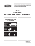
• FRAME—“POPPING/CREAKING”—FASTENER
REPLACEMENT
Article No.
97-3-10
• NOISE—“POPPING/CREAKING”—FRONT FRAME
OR SUSPENSION BRACKETS
FORD:
1980-1996 BRONCO, F-150, F-250 LD
1980-1997 F-250 HD, F-350
1988-1997 F SUPER DUTY, F-47
This TSB article is being republished in its entirety
to include vehicles built through the 1997 model
year and to update the Transmission Crossmember
Service Procedure.
ISSUE
A “popping/creaking” sound may come from the
area of the front frame or suspension brackets. This
may occur because of a slip/stick motion at a loose
rivet or bolt in a frame crossmember or a
suspension bracket (radius arm, spring tower, spring
shackle, etc.).
ACTION
Other underbody areas that produce similar noises
include:
• transfer case skid plate
• leaf spring bushings
• steering intermediate shafts
• shock bolts
• bumper brackets
• brakes
Other Service Bulletins have been published to
address the proper repair of these concerns.
DIAGNOSTIC PROCEDURE
Use the following Diagnostic Procedure to
determine the location of the noise. Replace the
suspected fastener(s) by referring to the following
Repair Procedure for details.
1.
a. Understand the customer’s description of the
noise and of the conditions under which it is
heard.
SOURCES OF VARIOUS FRONT UNDERBODY
NOISES
Various front underbody noises may originate from
several different sources and are often difficult to
locate and diagnose. Common noise locations
include:
• #1 (engine) crossmember rivets - primarily the
rivet or “huck fastener” at the lower left front,
behind the steering gear
• loose or improperly seated spring shock tower
rivets/bolts
• loose or misaligned transmission crossmembers
• loose or improperly seated front leaf spring
bracket rivets
• loose radius arm brackets
• loose axle pivot brackets
PROOF 3-APR-00
KTPL97003
INTERVIEW THE CUSTOMER
b. Road test the vehicle with the customer to
fully understand where, how, and when the
noise occurs.
2.
DUPLICATE THE NOISE CONCERN
a. Drive the vehicle around for at least 15
minutes to warm-up and exercise the frame
joints so that any frame noise is more likely
to be repeatable in the garage or on the
road.
b. Identify the conditions in which the noise is
repeatable. Does the noise occur:
• While parked and turning the wheels
lock-to-lock?
• Only when driving?
• While going straight over bumps?
• While on a lift with the suspension
unloaded?
• Only when the brakes are applied?
KTPL97003
PAGE 1
Article No. 97-3-10 Cont’d.
c. Identify the general location of the noise.
Can you “feel” the noise in the floorboard or
the steering wheel? Refer to Figure 9 for
likely locations for the noise.
NOTE
USE CHASSIS EARS AND/OR A STETHOSCOPE
TO DETERMINE THE LOUDEST POINT OF THE
NOISE. IF THE NOISE IS REPRODUCIBLE WHEN
STATIONARY, PUT THE VEHICLE ON A
DRIVE-ON LIFT AND “FEEL” FOR ANY
MOVEMENT OR VIBRATION AT THE JOINTS.
3.
INSPECT FRAME BOLTS FOR PROPER
INSTALLATION TORQUE
Inspect and tighten all front end components which
bolt to the frame to confirm that they are at the
proper torque (refer to the Repair Procedure section
of this article for proper torque requirements). This
includes, but is not limited to:
• radius arm bracket bolts
• axle pivot bracket bolts
• transmission crossmember bolts
• spring tower bolts
4.
INSPECT THE FRAME RIVETS
• Inspect all riveted frame and suspension
components in the general area of the noise
for loose or improperly seated rivets.
NOTE
TAP THE RIVETS WITH A SMALL HAMMER.
WHEN A RIVET IS NOT INSTALLED PROPERLY
IT WILL MAKE A DIFFERENT SOUND THAN A
“SNUG” RIVET.
• Service identified rivets according to the
procedure listed in the Repair Procedure
section.
5.
TEST DRIVE THE VEHICLE
Road test the vehicle again to duplicate the
concern. If the noise is still present, proceed to the
next Step.
6.
TEST JOINTS TO LOCATE NOISE
• Use a small pry bar as a “wedge” between
components suspected of causing the noise.
By pounding the wedge into a joint or behind
a bracket, the noise should change or be
eliminated if the noise is coming from that
location.
NOTE
USING A STETHOSCOPE, OR CHASSIS EARS,
WILL HELP TO IDENTIFY ANY NOISE CHANGE.
• If the source of the noise is identified,
proceed to the Repair Procedure section.
• If the source of the noise has not been
identified by this Step, investigate other
non-frame or suspension sources and/or
proceed to the next St ep.
7.
SERVICE THE VEHICLE
a. If the noise has been identified, proceed to
the specific component section in the Repair
Procedure.
b. If the noise source has not been identified,
refer to Figure 9 for general noise locations,
operating conditions and number of
occurrences. Proceed with repairing the
identified components.
REPAIR PROCEDURE - (A) THROUGH (H)
(A) “Huck Fastener” - Lower Left Front #1
Crossmember Rivet Replacement
This procedure should be done on flat ground or on
a drive-on lift, with the wheels pointed straight and
full weight resting on the wheels. This fastener
could be either a standard cold head rivet in light
duty applications or a large “huck” bolt which has
the appearance of a large “pop” rivet.
NOTE
USE WARRANTY DEALER CODING: 5020, AS
BASIC PART NO.
1.
Remove damaged or loose rivet:
COLD HEAD RIVETS:
• Drill a 3.175mm (1/8″) hole through the rivet.
• Redrill the same hole through the shank of the
rivet with a 9.525mm (3/8″) drill.
• Remove the rivet head with an air chisel.
• Drive out the rivet with a punch and hammer.
PAGE 2
KTPL97003
KTPL97003
PROOF 3-APR-00
Article No. 97-3-10 Cont’d.
“HUCK” RIVETS:
• Use a flat chisel and hammer (or air chisel) to
split the exposed collar of the huck fastener
(Figure 1).
• Knock the rivet pin out of the blind side with a
6.35mm (1/4″) drift punch and hammer (Figure 2).
• Cut the rivet’s head off with a hammer and flat
chisel (Figure 3).
• Knock the sleeve out of the blind side with a
9.525mm (3/8″) drift punch and hammer (Figure
4).
CAUTION
DO NOT REMOVE THE FASTENER WITH A
CUTTING TORCH BECAUSE DAMAGE TO THE
FRAME STRUCTURE IS LIKELY TO RESULT.
2.
3.
4.
After removing the rivet, verify the noise came
from this location by pounding a wedge
between the crossmember and the frame liner,
then driving the vehicle to reproduce the noise.
The wedge will lift the crossmember off of the
inner frame liner and eliminate any noise if the
lower left front #1 crossmember joint is the
source of the noise.
With the wedge still in place, insert the Bearing
Strip (F6TZ-5D033-BA) between the #1
crossmember and frame liner. Align the strip
approximately centered and extending well past
the hole location. Remove the wedge and drill a
11.113mm (7/16″) diameter hole through the
bearing strip.
Line ream the existing hole through the liner,
frame flange and crossmember to 14.288mm
(9/16″) (Figure 5). Remove any burrs after
reaming.
NOTE
TO PROPERLY REAM THE HOLE ON A VEHICLE
WITH LEAF SPRINGS, THE SPRING MUST BE
REMOVED TO PROVIDE VERTICAL ACCESS TO
THE RIVET HOLE.
5.
Install a 9/16″ Grade 8 torque prevailing Nut
(34990-S2) with a Washer (44880-S2) and a
Grade 8 Bolt (58698-S2) with a Washer
(44880-S2) (Figure 6).
a. Slide the bolt and washer into the “window”
opening on the outside of the frame siderail,
and insert it into the newly-reamed hole.
PROOF 3-APR-00
KTPL97003
NOTE
ON VEHICLES WITH QUAD SHOCK
ABSORBERS, IT MAY BE NECESSARY TO
REMOVE THE SHOCK/SPRING TOWER TO GAIN
ACCESS TO THE “WINDOW” IN THE SIDERAIL.
b. Install the washer and nut and torque nut to
190 ±4 N•m (140 ±3 lb-ft). Turn the wheels
lock-to-lock several times to seat the joint
and retorque. Tack weld the nut to the bolt
after tightening.
CAUTION
DO NOT WELD THE NUT/WASHER TO THE
FRAME.
NOTE
ON HEAVY DUTY VEHICLES, IT MAY BE
NECESSARY TO UPGRADE THE REPLACEMENT
FASTENER TO A 5/8″ GRADE 8 TORQUE
PREVAILING NUT (34991-S2), BOLT (58720-S100)
AND TWO (2) WASHERS (44881-S2) TORQUED
TO 250 ±6.8 N•m (185 ±5 LB-FT).
(B) Other #1 Crossmember Rivets
NOTE
USE WARRANTY DEALER CODING: 5020, AS
BASIC PART NO.
Follow the “Huck Fastener”/Repair Procedure A,
listed in this article for cold head rivets and replace
the rivet with a 9/16″ Grade 8 torque prevailing Nut
(34990-S2) with a Washer (44880-S2) and a Grade
8 Bolt (58698-S2) with a Washer (44880-S2).
(C) Other Rivets
NOTE
USE WARRANTY DEALER CODING: 5004, AS
BASIC PART NO.
Follow TSB 96-15-11 for proper rivet replacement
procedure.
(D) Transmission Crossmember
NOTE
USE WARRANTY DEALER CODING: 5060, AS
BASIC PART NO.
This procedure should be done on flat ground or on
a drive-on lift, with the wheels pointed straight and
full weight resting on the wheels.
NOTE
A SIMILAR NOISE CAN OCCUR AT THE
TRANSFER CASE SKID PLATE ATTACHMENTS
AND SHOULD BE INVESTIGATED IN
KTPL97003
PAGE 3
Article No. 97-3-10 Cont’d.
CONJUNCTION WITH THIS REPAIR
PROCEDURE.
c. Torque the crossmember-to-frame bolts
(Figure 7, Number 3).
1.
d. Torque the gusset-to-crossmember bolts
(Figure 7, Number 4).
Remove transmission weight:
a. Remove bolts attaching transmission mount
to the crossmember.
7.
b. Lift the transmission to remove any load to
the crossmember. The crossmember should
now be completely loose.
NOTE
YOU MAY NOTICE THE FRAME RAILS TWIST
SLIGHTLY AND “RELAX” AFTER THIS NEXT
STEP.
2.
a. Torque the gusset-to-frame bolts (Figure 8,
Number 1).
b. Torque the crossmember-to-frame bolts
(Figure 8, Number 2).
Loosen crossmember:
c. Torque the gusset-to-crossmember bolts
(Figure 8, Number 3).
a. Loosen all bolts attaching the crossmember
to the frame siderails.
b. Loosen all bolts attaching the crossmember
gusset(s) to the crossmember and to the
frame siderails. The crossmember should
now be completely loose.
3.
4.
Turn the steering wheel lock-to-lock and then
straighten the wheels. This helps to remove any
stress in the frame.
8.
5.
Secure the crossmember attaching hardware.
Determine which style of crossmember the
vehicle is equipped with, and follow Step 6 or
7.
6.
If the vehicle has a wraparound-style
crossmember (Figure 7), torque each grouping
of fasteners in the order listed in the following
Substeps to 70 ±10.5 N•m (52 ±8 lb-ft).
a. Torque all three (3) bolts/nuts at the
crossmember-to-frame siderail at the
wraparound side (Figure 7, Number 1).
b. Torque the gusset-to-frame bolts (Figure 7,
Number 2).
PAGE 4
KTPL97003
Reattach transmission:
a. Lower the transmission.
b. Reattach the transmission using new Nuts
(N621945-S2) and torque to 95 ±15 N•m
(70 ±11 lb-ft).
9.
Inspect gusset/crossmember joint:
a. Visually inspect the joint between the gusset
and crossmember. If all fasteners have been
torqued properly and any gap exists
between the two, shim joint with washers.
Install new crossmember fastening hardware
one at a time and replace each nut and bolt
with a new Nut (N800937-S427) and Bolt
(N802114-S2) and leave them loosely
assembled until all crossmember and gusset
fasteners have been replaced.
NOTE
IT IS IMPERATIVE THAT THE FOLLOWING
TIGHTENING SEQUENCE BE FOLLOWED.
If the vehicle has a double-gusseted
crossmember (Figure 8), torque each grouping
of fasteners in the order listed in the following
Substeps to 70 ±10.5 N•m (52 ±8 lb-ft) and
repeat for the other side.
b. Reattach the gusset with new Bolts
(N802114-S2) and Nuts (N800937-S427)
torqued to 70 ±10.5 N•m (52 ±7 lb-ft).
NOTE
ON HEAVY DUTY VEHICLES, IT MAY BE
NECESSARY TO UPGRADE THE REPLACEMENT
FASTENER TO A 9/16″ GRADE 8 TORQUE
PREVAILING NUT (34990-S2) AND BOLT
(58698-S2) TORQUED TO 190 ±4 N•m (140 ±3
LB-FT).
(E) Radius Arm Brackets
NOTE
USE WARRANTY DEALER CODING: 3B095, AS
BASIC PART NO.
1.
Inspect and retorque all radius arm bracket
bolt(s) to 135 ±20 N•m (100 ±15 lb-ft).
NOTE
IF THE BOLT IS VERY LOOSE AND THE
BRACKET IS NOT CLAMPED TIGHTLY, INSPECT
KTPL97003
PROOF 3-APR-00
Article No. 97-3-10 Cont’d.
THE FRAME AND BRACKET HOLES FOR
ELONGATION. IF A BRACKET HOLE IS
ELONGATED, THE BRACKET MUST BE
REPLACED. IF A FRAME HOLE IS ELONGATED,
THE ENTIRE FRAME MUST BE REPLACED, OR
THE FRAME AND BRACKET HOLES MUST BE
DRILLED OUT TO A LARGER SIZE, NOT TO
EXCEED 15mm (19/32″), AND A LARGER NUT
AND BOLT MUST BE INSTALLED.
2.
Inspect the rivets for looseness. Replace any
loose or poorly seated rivets using the following
procedure:
NOTE
MOST OFTEN, THE NOISE CAN BE ELIMINATED
BY REPLACING ONLY THE MIDDLE RIVET OF
THE THREE (3) SECURING THE BRACKET.
a. Remove damaged or loose rivet:
• Drill a 3.175mm (1/8″) hole through the
rivet.
• Redrill the same hole through the shank
of the rivet with a 9.525mm (3/8″) drill.
• Remove the rivet head with an air chisel.
• Drive out the rivet with a punch and
hammer.
CAUTION
DO NOT REMOVE THE FASTENER WITH A
CUTTING TORCH BECAUSE DAMAGE TO THE
FRAME STRUCTURE IS LIKELY TO RESULT.
b. Redrill the same hole through the shank of
the rivet with a 9.525mm (3/8″) drill.
c. Remove the rivet head with an air chisel.
d. Drive out the rivet with a punch and
hammer.
CAUTION
DO NOT REMOVE THE FASTENER WITH A
CUTTING TORCH BECAUSE DAMAGE TO THE
FRAME STRUCTURE IS LIKELY TO RESULT.
2.
Line ream the hole to the replacement bolt size
of 11.113mm (7/16″).
3.
Clean hole of burrs after reaming so that the
bolt head and nut will seat properly.
4.
Install a new Bolt (56561-S2) and Nut
(382400-S2), and torque to 89 ±13 N•m (66
±10 lb-ft).
(G) Front Leaf Spring Brackets
NOTE
USE WARRANTY DEALER CODING: 5340, AS
BASIC PART NO.
Inspect the rivets for looseness. Replace any loose
or poorly seated rivets using the following
procedure.
1.
a. Drill a 3.175mm (1/8″) hole through the
rivet.
b. Line ream the hole to the replacement bolt
size of 12.7mm (1/2″).
b. Redrill the same hole through the shank of
the rivet with a 8.731mm (11/32″) drill.
c. Clean hole of burrs after reaming so that
the bolt head and nut will seat properly.
c. Remove the rivet head with an air chisel.
d. Install a new Bolt (N802210-S2) and Nut
(N800937-S427), and torque to 133 ±20
N•m (98 ±15 lb-ft).
(F) Spring Towers
NOTE
USE WARRANTY DEALER CODING: 5A306, AS
BASIC PART NO.
Inspect the rivets for looseness. Replace any loose
or poorly seated rivets using the following
procedure.
1.
Remove damaged or loose rivet:
a. Drill a 3.175mm (1/8″) hole through the
rivet.
PROOF 3-APR-00
KTPL97003
Remove damaged or loose rivet:
d. Drive out the rivet with a punch and
hammer.
CAUTION
DO NOT REMOVE THE FASTENER WITH A
CUTTING TORCH BECAUSE DAMAGE TO THE
FRAME STRUCTURE IS LIKELY TO RESULT.
2.
Install a new Bolt (58634-S2), two (2) Washers
(44877-S2) and a Nut (34987-S2). Torque to 62
±15 N•m (46 ±11 lb-ft).
(H) Axle Pivot Brackets
NOTE
USE WARRANTY DEALER CODING: 3B178, AS
BASIC PART NO.
KTPL97003
PAGE 5
Article No. 97-3-10 Cont’d.
Inspect and retorque all axle pivot bracket bolts
(torque values may vary by model - refer to the
appropriate light truck Service Manual for proper
torque specifications).
NOTE
IF THE BOLT IS LOOSE AND THE BRACKET IS
NOT CLAMPED TIGHTLY, INSPECT THE FRAME
AND BRACKET HOLES FOR ELONGATION. IF A
FRAME HOLE IS ELONGATED, THE ENTIRE
FRAME MUST BE REPLACED. NO FRAME
REPAIRS ARE AUTHORIZED ON THESE #1
CROSSMEMBER HOLES.
PART NUMBER
34990-S2
44880-S2
58698-S2
34991-S2
44881-S2
58720-S100
N802114-S2
N800937-S427
N621945-S2
N802210-S2
56561-S2
382400-S2
58634-S2
44877-S2
34987-S2
F6TZ-5D033-BA
PART NAME
Grade 8 Torque Prevailing Nut - 9/16″
Washer - 9/16″ (Pk/12)
Grade 8 Bolt - 9/16″-12x1.75 (Pk/4)
Grade 8 Torque Prevailing Nut - 5/8″
Washer - 5/8″ (Pk/12)
Grade 8 Bolt - 5/8″ (Pk/4)
Bolt
Nut
Nut
Bolt
Bolt
Nut
Bolt
Washer
Nut
Low Friction Insert
OTHER APPLICABLE ARTICLES: 96-15-11
SUPERSEDES: 96-4-11
WARRANTY STATUS: Eligible Under The
Provisions Of Bumper To
Bumper Warranty Coverage
For 1992-96 Model Years,
Basic Warranty Coverage
For All Others
OPERATION DESCRIPTION
TIME
970310A
Perform Diagnostics 0.7 Hr.
Includes Road Test
970310B
“Huck Fastener” - Replace 1.1 Hr.
(Repair A) - Includes
Additional Road Test And
Transmission
Crossmember Repair
(Repair D) - Not To Be
Used With Operation D
970310CA
#1 Crossmember And
0.9 Hr.
Other Rivets - Replace
Two (Repairs B And C)
970310CB
#1 Crossmember And
1.3 Hrs.
Other Rivets - Replace
Three (Repairs B And C)
PAGE 6
KTPL97003
970310CC
970310CT
970310C
970310D
970310E
970310FT
970310F
970310GT
970310G
970310HA
970310HB
970310HC
970310HT
970310H
970310IA
970310IB
970310IC
KTPL97003
#1 Crossmember And
Other Rivets - Replace
Four (Repairs B And C)
#1 Crossmember And
Other Rivets - Replace
Five Or More (Repairs B
And C)
#1 Crossmember And
Other Rivets - Replace
One (Repairs B And C)
Transmission
Crossmember (Repair D) Not To Be Used With
Operation B
Radius Arm Bracket
(Repair E) - Inspect And
Check Fastener Torque
Radius Arm Bracket Replace Both (Repair E) Not To Be Used With
Operations G And GT
Radius Arm Bracket Replace One (Repair E) Not To Be Used With
Operations G And GT
Radius Arm Bracket Rivet
- Replace Both (Repair E)
- Not To Be Used With
Operations F And FT
Radius Arm Bracket Rivet
- Replace One (Repair E) Not To Be Used With
Operations F And FT
Spring Tower Rivet Replace Two (Repair F)
Spring Tower Rivet Replace Three (Repair F)
Spring Tower Rivet Replace Four (Repair F)
Spring Tower Rivet Replace Five Or More
(Repair F)
Spring Tower Rivet Replace One (Repair F)
Front Leaf Spring Bracket
Rivet - Replace Two
(Repair G)
Front Leaf Spring Bracket
Rivet - Replace Three
(Repair G)
Front Leaf Spring Bracket
Rivet - Replace Four
(Repair G)
1.7 Hrs.
2.1 Hrs.
0.5 Hr.
0.5 Hr.
0.2 Hr.
1.3 Hrs.
0.7 Hr.
0.9 Hr.
0.5 Hr.
1.0 Hr.
1.4 Hrs.
1.8 Hrs.
2.2 Hrs.
0.6 Hr.
0.9 Hr.
1.3 Hrs.
1.7 Hrs.
PROOF 3-APR-00
Article No. 97-3-10 Cont’d.
970310IT
Front Leaf Spring Bracket 2.1 Hrs.
Rivet - Replace Five Or
More (Repair G)
970310I
Front Leaf Spring Bracket
0.5 Hr.
Rivet - Replace One
(Repair G)
970310J
Axle Pivot Bracket 0.2 Hr.
Inspect And Check
Fastener Torque
DEALER CODING
CONDITION
BASIC PART NO.
CODE
3B095 FOR REPAIR PROCEDURE
E
56
3B178 FOR REPAIR PROCEDURE
H
56
5004 FOR REPAIR PROCEDURE C
56
5020 FOR REPAIR PROCEDURE A
56
5020 FOR REPAIR PROCEDURE B
56
5060 FOR REPAIR PROCEDURE D
56
5340 FOR REPAIR PROCEDURE G
56
5A306 FOR REPAIR PROCEDURE
F
56
OASIS CODES: 305000, 390000, 702000, 702100
Figure 2 - Article 97-3-10
Figure 3 - Article 97-3-10
Figure 1 - Article 97-3-10
PROOF 3-APR-00
KTPL97003
KTPL97003
PAGE 7
Article No. 97-3-10 Cont’d.
Figure 4 - Article 97-3-10
Figure 5 - Article 97-3-10
Figure 6 - Article 97-3-10
PAGE 8
KTPL97003
KTPL97003
PROOF 3-APR-00
Article No. 97-3-10 Cont’d.
Figure 7 - Article 97-3-10
Figure 8 - Article 97-3-10
PROOF 3-APR-00
KTPL97003
KTPL97003
PAGE 9
Figure 9 - Article 97-3-10
PAGE 10
KTPL97003
KTPL97003
PROOF 3-APR-00