1
For Husqvarna Parts Call 606-678-9623 or 606-561-4983
Workshop manual
ZTH
English
www.mymowerparts.com
For Husqvarna Parts Call 606-678-9623 or 606-561-4983
www.mymowerparts.com
Sve-5 225/232/235 Bruk
31
97-11-25, 08.46
Svenska –
31
For Husqvarna Parts Call 606-678-9623 or 606-561-4983
WORKSHOP MANUAL
RIDE-ON LAWN MOWER
ZTH
Contents
Contents ..................................................................1
Safety Instructions .................................................3
General Instructions.............................................3
Special Instructions..............................................3
Explanation of Symbols ........................................5
Tools .......................................................................6
Technical Data ........................................................7
Delivery and Dealer Service ................................11
Pre-delivery Service...........................................11
After the First 8 Hours........................................12
25 Hour Service .................................................12
50 Hour Service .................................................12
100 Hour Service ...............................................13
300 Hour Service ...............................................13
At Least Once a Year.........................................14
Maintenance Schedule ......................................15
Delivery Servicing ................................................19
To our Dealers ...................................................19
Removing the Mower from its Packaging ..........19
Delivery Service .................................................20
Test Running......................................................24
Administration ....................................................24
Design and Function ............................................25
General ..............................................................25
Mower Identification ...........................................25
Engine................................................................27
Drive and Control ...............................................27
Brakes................................................................27
Mower Deck .......................................................28
Repairs ..................................................................29
Engine................................................................29
Adjusting the Throttle Wire.................................31
Checking and Adjusting the Choke Wire ...........32
Fuel tank ............................................................33
Adjusting Motion Control Lever Linkages ..........34
Adjusting Motion Control Lever Spring-back......34
Adjusting the Park Brake ...................................34
Mower Deck .......................................................35
Spindle Blade Bearings.....................................36
Sharpening and Balancing Blades.....................37
Setting the Mower Deck ....................................38
Deck Belt............................................................38
Hydraulic Pump Belt ..........................................40
Front Wheel Bearings ........................................41
Electrical System ................................................ 43
Troubleshooting ................................................ 43
Wiring Assembly ............................................... 43
Battery............................................................... 46
Fuses ................................................................ 46
Relays ............................................................... 47
Starter Motor Contactor..................................... 47
Ignition and Start Switch ................................... 48
Hour Meter ........................................................ 48
Blade Switch ..................................................... 49
Mower Deck Clutch ........................................... 49
Motion Control Switches ................................... 50
Park Brake Interlock Switch .............................. 51
Welding ............................................................. 52
Hydraulic System ................................................ 53
Hydraulics Hygiene ........................................... 53
Hydraulic Oils .................................................... 54
Correct Oil Leaks .............................................. 54
Keep Hydraulic Oil Clean .................................. 54
Work Methods ................................................... 54
ZTH Hydraulic System ...................................... 55
Hydraulic Tank .................................................. 56
The Cooler for the Hydraulic System ................ 57
Hydraulic Filter .................................................. 57
Hydraulic Lines.................................................. 57
Hydraulic Pump................................................. 58
Hydraulic Motors ............................................... 60
Troubleshooting .................................................. 61
Engine ............................................................... 61
Wiring Harness.................................................. 61
Clutch ................................................................ 63
Hydraulic Pump................................................. 66
English-1
www.mymowerparts.com
For Husqvarna Parts Call 606-678-9623 or 606-561-4983
English-2
www.mymowerparts.com
For Husqvarna Parts Call 606-678-9623 or 606-561-4983
SAFETY INSTRUCTIONS
Safety Instructions
General Instructions
This workshop manual has been written for users who have a good understanding of the repair and
servicing of ride-on mowers.
The workshop where the ride-on mower is repaired must have have all the safety systems demanded by
local regulations.
No one is to attempt to repair the ride-on mower without having first read and understood the contents of
this manual.
The ride-on mower has been safety tested. Safety approval applies only when the ride on-mower uses
parts or equipment supplied or recommended by Husqvarna Turf Care.
Special Instructions
The fuel used in the ride-on mower is hazardous if used incorrectly. Pay particular attention to the following:
•
The fuel and the fumes it gives off are toxic.
•
Eye and skin complaints can result from incorrect exposure.
•
Breathing difficulties can result from incorrect exposure.
•
The fuel and fumes are highly flammable.
When using compressed air, users must not direct the air stream towards themselves or any other person.
Air may penetrate the blood stream and cause life-threatening damage.
Use hearing protectors when test driving.
After test driving, do not touch the muffler before it has cooled down (danger of burns). This especially
applies if the ride-on mower has a catalytic converter. If consumed, the lining on and in the catalytic
converter element can damage health. Wear protective gloves whenever working on the catalytic converter
or the silencer.
With the engine running, many engine and drive system components become hot and may cause burns if
touched. Do not touch such components before they have cooled down.
When draining oil from a hot engine or hot hydraulic system, be aware that the oil can be hot enough to
cause burns. Wear protective glasses whenever there is a risk of splashing.
The mower blades are sharp. To avoid cuts, always wear protective gloves when handling the blades.
Wear protective glasses when working with springs. Springs can detach from their mounts and fly with
great force into unprotected eyes.
Use the right tools for each job. Check all tools before using them and repair or replace as necessary.
English-3
www.mymowerparts.com
For Husqvarna Parts Call 606-678-9623 or 606-561-4983
SAFETY REGULATIONS
Keep the workplace clean and tidy. Ensure that illumination is good, that tools which are not being used
are stored appropriately and that all waste (scrap, swarf, etc.) is immediately placed in the appropriate
container. Pay particular attention to keeping the floor clean so that there is no risk of slipping or tripping.
Be extremely careful when handling battery acid. Severe burns may result if the acid touches the skin. If
acid is spilt on the skin, drench immediately with running water.
Always wear protective glasses when handling battery acid. Blindness may result if acid gets into the eyes.
If there is an accident, take immediate action and contact a doctor as soon as possible.
Be careful when working on the battery. Explosive gas is formed in the battery. Never handle the battery
when smoking or in the vicinity of naked flames or sparks (the battery may explode and cause severe
injuries).
During certain maintenance and service operations, it is required that the mower be rendered incapable of
starting. This is to prevent injury to those working on or standing near the mower.
Hydrostatic braking may be lost if there is a failure in the hydrostatic drive.
Certain solvents and cleaning agents are flammable. Do not use them whenever there is a less dangerous
alternative. Never use flammable solvents in areas where there is a risk of ignition. Dispose of used
cleaning agents in sealed containers.
Respect the environment. Ensure that all solvents, waste oil and used oil filters are handled in an
environment-friendly way. Observe all local regulations on the environment. A Husqvarna workshop must
look clean at all times!
In this workshop manual, “warning boxes” containing further safety instructions will be found next to certain
work instructions. Observe these safety instructions, they are there for your protection.
In this workshop manual, all locators (“right”, “left”, etc.) are judged as viewed from behind the forwardfacing mower (i.e. as if standing directly behind the mower when it is ready to drive forwards).
English-4
www.mymowerparts.com
For Husqvarna Parts Call 606-678-9623 or 606-561-4983
EXPLANATION OF SYMBOLS
Explanation of Symbols
The symbols below are used on the mower and in this manual. Study them carefully and be aware of what
they mean.
WARNING!
Xxxxxxx xxxx xxxxxxxx xxx x.
xxxx xxxxxx xx.
Is used in this manual to make the user aware that there is a danger of personal injury, especially if the
special instructions are not followed.
IMPORTANT INFORMATION
Xxxxxxx xxxx xxxxxxxx xxx x
xxxx xxxxxx xx.
Is used in this manual to make the user aware that there is a danger of material damage, especially if the
special instructions are not followed. It is also used where it is judged that there is a danger of incorrect
handling or incorrect assembly/fitting.
Reverse
Warning!
Neutral
Park brake
Fast
Slow
CE conformity
marking
Battery acid is corrosive, explosive and
flammable.
Choke
Warning! Rotating blades,
stand clear of the chute.
Do not stand here.
Fuel
Do not touch rotating
parts.
Max. sound emission.
Use ear protectors.
English-5
www.mymowerparts.com
For Husqvarna Parts Call 606-678-9623 or 606-561-4983
TOOLS
Tools
The mower’s special design means that most repair and maintenance work can be carried out using
standard tools.
Servicing of engines and hydraulic pumps requires special tools. These are listed in the service manuals of
the individual manufacturers.
The mower (engine excluded) has mainly UNC or UNF screw/bolt/nut threads. Certain nuts have special
stiffy threads for securing. It is vital that exactly the right size tools (i.e. imperial measurement) are used on
these.
Those working on the mower must have ready access to socket wrench sets and open end wrenches of the
following sizes:
•
3/8"
•
7/16"
•
1/2"
•
9/16"
•
5/8"
•
11/16"
•
3/4"
The following are also required:
•
Torque wrenches, 12 Nm - 110 Nm.
•
15/16" socket for torque tightening of blade bolts.
•
7/8" open end wrench or combination wrench for torque tightening of hydraulic lines.
•
A set of small, imperial measurement, Allen keys.
WARNING!
If metric or other unsuitable tools are used, there is a danger that they will slip
and cause personal injury. They may also damage the surfaces of the nut or bolt
in such a way that tools can no longer get a firm grip.
English-6
www.mymowerparts.com
For Husqvarna Parts Call 606-678-9623 or 606-561-4983
TECHNICAL DATA
Technical Data
Model
ZTH5223
Model part number
968 99 91 60
Engine (spec. number)
Kawasaki (FH680V-AS15)
Kawasaki (FH721V-AS04)
Cylinder diameter
75.2 mm (2.96 in.)
75.2 mm (2.96 in.)
Cylinder stroke
76 mm (2.99 in.)
76 mm (2.99 in.)
Cylinder volume
675 cc (41.19 cu.in.)
675 cc (41.19 cu.in.)
Power
23 hp
25 hp
Engine RPM
2,950 RPM
2,950 RPM
Idle RPM
1,550 RPM
1,550 RPM
Spark plugs (2)
NGK BPR4ES
NGK BRR1550
Oil capacity, engine (total)
1.8 litres (3.8 US pints)
1.8 litres (3.8 US pints)
Engine weight
40.5 kg (89.3 lbs)
41.2 kg (90.8 lbs)
Cutting width
1321 mm (52 in.)
1549 mm (61 in.)
Blade length
457.2 mm (18 in.)
533.4 mm (21 in.)
Tightening torque, blade bolt
122 Nm (90 ft/lb)
122 Nm (90 ft/lb)
Cutting height
Adjustable 38 mm (1.5") to
152 mm (6") in 64 mm
(0.25") increments
Adjustable 38 mm (1.5") to
152 mm (6") in 64 mm
(0.25") increments
Blade engagement
Warner Mag-Stop
Electromagnetic clutch
Warner Mag-Stop
Electromagnetic clutch
Slip torque, clutch
271 Nm (200 ft/lb)
271 Nm (200 ft/lb)
Clutch coil resistance
1.74 - 1.93 ohms at 23°C (68°F)
1.74 - 1.93 ohms at 23°C (68°F)
Supply voltage clutch
12 - 14 V
12 - 14 V
Tightening torque, clutch bolt
67 Nm (50 ft/lb)
67 Nm (50 ft/lb)
Blade tip speed
4,704 m/min.
4,541 m/min
Anti-scalp rollers
6, adjustable
6, adjustable
Tightening torque, bolt for
mower deck pulley
61 Nm (45 ft/lb)
61 Nm (45 ft/lb)
Hydrostatic drive
Dual Hydro-gear pumps and
Parker/Ross Wheel drive motors
Dual Hydro-gear pumps and
Parker/Ross Wheel drive motors
Tightening torque, pipe
couplings
41 Nm (30 ft/lb)
41 Nm (30 ft/lb)
Hydraulic pumps (2)
Hydro Gear BDP 10A 404
Hydro Gear BDP 10A 404
ZTH6125
English-7
www.mymowerparts.com
For Husqvarna Parts Call 606-678-9623 or 606-561-4983
TECHNICAL DATA
Model
ZTH5223
ZTH6125
Displacement
10.2 cc/r (0.623 cu. in./rev)
10.2 cc/r (0.623 cu. in./rev)
Nominal working pressure
70 bars (1000 PSI)
70 bars (1000 PSI)
Max. hydraulic pressure
145 bars (2,100 PSI)
145 bars (2,100 PSI)
Max. hydraulic oil temp
110°C (230°F)
110°C (230°F)
Weight, hydraulic pump
3.6 kg (8 lbs)
3.6 kg (8 lbs)
Hydraulic motors (2)
Parker Ross
Parker Ross
Tightening torque, wheel motor
hub nut
122 Nm (90 ft/lb)
122 Nm (90 ft/lb)
Hydraulic oil
1.9 litres (2 qt.), 15W-50
Synthetic
1.9 litres (2 qt.), 15W-50
Synthetic
Hydraulic oil cooler
Yes
Yes
Speed forward
Variable, max. 12.9 km/h
(8 mph)
Variable, max. 12.9 km/h
(8 mph)
Speed reverse
Variable, max. 3.23 km/h
(2 mph)
Variable, max. 3.23 km/h
(2 mph)
Rear tires
Carlisle 24" X 12.00 - 12 Tubeless
Turf Master
Carlisle 24" X 12.00 - 12 Tubless
Turf Master
Tightening torque, lug nuts
100 Nm (75 ft/lb)
100 Nm (75 ft/lb)
Front tires
Carlisle 13" X 5.00 - 6 Tubeless
Carlisle 13" X 5.00 - 6 Tubeless
Electrical system
12 V with 15 A charging system
12 V with 15 A charging system
Fuel capacity
44 litres (11.4 US Gal.), 22 litres/
tank
44 litres (11.4 US Gal.), 22 litres/
tank
Seat
Adjustable, high-back seat with
armrests
Adjustable, high-back seat with
armrests
Overall length
2057 mm (81 in.)
2057 mm (81 in.)
Overall width (chute up)
1346 mm (53 in.)
1575 mm (62 in.)
Overall width (chute down)
1600 mm (63 in.)
1829 mm (72 in.)
Overall height
1073 mm (42.25 in.)
1073 mm (42.25 in.)
Weight
464.5 kg (1024 lbs.)
464.5 kg (1024 lbs.)
1/4"
12 Nm (9 ft/lb)
12 Nm (9 ft/lb)
5/16"
25 Nm (18 ft/lb)
25 Nm (18 ft/lb)
3/8"
44 Nm (33 ft/lb)
44 Nm (33 ft/lb)
Tightening torque, standard
bolts
English-8
www.mymowerparts.com
For Husqvarna Parts Call 606-678-9623 or 606-561-4983
TECHNICAL DATA
Model
ZTH5223
ZTH6125
7/16"
70 Nm (52 ft/lb)
70 Nm (52 ft/lb)
1/2"
110 Nm (80 ft/lb)
110 Nm (80 ft/lb)
BioClip adapter
Optional
Optional
Foot controlled mower deck lift
Optional
Optional
Deluxe seat
Optional
Optional
Accessories
English-9
www.mymowerparts.com
For Husqvarna Parts Call 606-678-9623 or 606-561-4983
TECHNICAL DATA
English-10
www.mymowerparts.com
For Husqvarna Parts Call 606-678-9623 or 606-561-4983
DELIVERY AND DEALER SERVICE
Delivery and Dealer Service
Pre-delivery Service
1.
Charge the battery.
2.
Mount the rear tires.
3.
Check and adjust the tire pressure in all
tires. All tires should be1 bar (15 PSI).
4.
Fit the motion control levers in the normal
position.
5.
Connect the rod to the seat stop.
6.
Connect the contactor to the cable for the
seat’s safety switch.
7.
Fit the armrests to the seat’s back
support.
8.
Check that the engine has the right
quantity of oil.
9.
Check that the hydraulic tank has the
right quantity of oil.
10. Adjust the position of the motion control
levers.
11. Fuel the mower and open the gas valve.
12. Connect exhaust fume extraction.
13. Start the engine.
14. Vent the hydraulic system.
15. .Check that there is drive to both wheels
16. Check mower deck settings.
17. Check:
The park brake safety switch.
The seat safety switch.
The motion control lever safety switches.
Correct park brake operation.
Forward drive.
Reverse drive.
Blade engagement.
18. Check the idling speed (1,550 ±50 rpm).
19. Check max. engine speed (2,800 ±75
rpm).
English-11
www.mymowerparts.com
For Husqvarna Parts Call 606-678-9623 or 606-561-4983
DELIVERY AND DEALER SERVICE
20. Inform the customer of the:
Necessity and advantages of following
the maintenance schedules.
Necessity and advantages of having the
mower inspected every 300 hours.
The effect on resale value of regular
servicing and a fully stamped service
book.
The use of BioClip.
21. Complete the sales certificate, etc.
After the First 8 Hours
Change the motor oil.
25 Hour Service
1.
Check the fuel pump air filter.
2.
Check the oil level in the hydraulic
system.
3.
Check tire pressure.
4.
Lubricate the mower deck’s belt
tensioner.
5.
Lubricate the hydraulic pump’s belt
tensioner.
6.
Check/clean the engine’s cold air intake.
7.
Clean the air cleaner’s pre-filter (Oilfoam).
50 Hour Service
1.
Carry out a 25 hour service.
2.
Clean/change the air cleaner’s filter
cartridge (paper filter). Perfom more
reqularly in dusty operating conditions.
3.
Lubricate the bearings of the front
wheels.
4.
Lubricate the shafts of the motion control
levers.
5.
Lubricate the mower deck struts.
6.
Lubricate the cutting height regulator.
7.
Check/adjust the park brake.
English-12
www.mymowerparts.com
For Husqvarna Parts Call 606-678-9623 or 606-561-4983
DELIVERY AND DEALER SERVICE
100 Hour Service
1.
Carry out a 25 hour service.
2.
Carry out a 50 hour service.
3.
Change the engine oil.
4.
Check if the hydraulic oil needs changing
(every 300 hours).
5.
Check if the engine’s oil filter needs
changing (every 200 hours).
6.
Clean/change the spark plugs.
7.
Change the fuel filter in the fuel line.
8.
Clean the engine and transmission
cooling fins.
9.
Clean and check if the air filter’s paper
cartridge needs changing (every 200
hours).
300 Hour Service
1.
Inspect the machine. Reach agreement
with the customer on what additional
work is to be carried out.
2.
Carry out a 25 hour service.
3.
Carry out a 50 hour service.
4.
Carry out a 100 hour service.
5.
Change the oil and the filter in the
hydraulic system.
6.
Clean the combustion chamber and
grind the valve seats.
7.
Check the play in the engine valves.
8.
Change the air cleaner’s pre-filter (Oilfoam).
English-13
www.mymowerparts.com
For Husqvarna Parts Call 606-678-9623 or 606-561-4983
DELIVERY AND DEALER SERVICE
At Least Once a Year
1.
Clean the engine’s cold air intake (25
hours).
2.
Change the air cleaner’s pre-filter (Oilfoam).
3.
Change the paper cartridge in the air
filter (200 hours).
4.
Change the engine oil (100 hours).
5.
Change the engine’s oil filter (200 hours).
6.
Change the oil and the filter in the
hydraulic system.
7.
Check/adjust the cutting height regulator.
8.
Check/adjust the park brake (50 hours).
9.
Clean/change the spark plugs (100
hours).
10. Change the fuel filter in the fuel line (100
hours).
11. Clean the cooling fins (100 tim).
12. Check the play in the engine valves (300
hours).
13. A 300 hour service to be carried out by
an authorized workshop.
English-14
www.mymowerparts.com
For Husqvarna Parts Call 606-678-9623 or 606-561-4983
DELIVERY AND DEALER SERVICE
Maintenance Schedule
The table below lists the maintenance required by the ride-on mower. Several of the points not covered in
this workshop manual will be found in the Operating Instructions.
Daily
Maintenance
Weekly
Page Pre- After
use use
Check for fuel and oil leaks.
-
❍
Check the park brake.
-
●
21
●
Check engine oil level (every fueling).
▼
Check the fuel pump air filter.
-
Check the safety systems.
-
Check/clean the engine’s cold air intake.
-
▼
38
●
Check fasteners (bolts, nuts, etc.).
-
❍
Start engine and blades; check for abnormal
noise.
-
❍
Clean the underside of the mower deck.
-
▼
Check the mower deck.
▼
●
Check hydraulic system oil level.
22
Check the condition of belts, pulleys, etc.
38
●
-
❍
Check for any damage.
Check tire pressure.
At Maintenance intervals
in hours
least
once 25
50 100 300
a
year
●
20
-
❍
53
●
Clean thoroughly around belts, pulleys, etc.
-
❍
Lubricate mower deck belt tensioner.
-
▼
Lubricate belt tensioner for hydraulic pumps.
-
▼
Lubricate all wires.
-
▼
Lubricate driver’s seat mechanisms.
-
▼
Lubricate the throttle control.
-
▼
Clean the engine’s cold air intake.
-
Lubricate mower deck links.
-
Lubricate front wheel mounts (every 200 hours).
-
Lubricate front wheel bearings.
-
▼
Lubricate the shafts of the motion control levers.
-
▼
Lubricate mower deck struts.
-
▼
Lubricate the mower deck’s height regulator.
-
▼
Clean thoroughly around the engine.
Clean thoroughly around the hydraulic system.
▼
▼
❍
▼
English-15
www.mymowerparts.com
For Husqvarna Parts Call 606-678-9623 or 606-561-4983
DELIVERY AND DEALER SERVICE
Daily
Maintenance
Weekly
Page Pre- After
use use
At Maintenance intervals
in hours
least
once 25
50 100 300
a
year
38
●
-
▼
-
▼
22
●
56
●
Change the engine’s oil filter (every 200 hours).
-
▼
▼
Clean/change the spark plugs.
-
❍
❍
Change the fuel filter in the fuel line.
-
▼
▼
Clean the cooling fins.
-
❍
❍
Check the play in the engine valves 4) .
-
❍
❍
Change the air cleaner’s pre-filter (Oil-foam).
-
▼
▼
Change air filter (paper filter) 2) (every 200 hours).
-
▼
13
●
34
●
Check/adjust the cutting height regulator.
Clean the air cleaner’s pre-filter (Oil-foam).
Clean the air cleaner’s filter
2)
(paper filter).
Change the motor oil 1) .
Change the hydraulic oil (every 300 hours).
Carry out a 300 hour service
Check/adjust the park brake.
4)
.
▼
▼
●
●
▼
●
●
1)
First change after 8 hours. With heavy operating conditions or high ambient temperature, change every 50 hours. 2) In dusty conditions, clean and
change more frequently. 3) Where the mower is in daily use, lubrication must be carried out twice a week. 4) To be carried out by an authorized workshop.
● = Covered in this workshop manual.
❍ = Not coverd in this workshop manual or the Operating Instructions.
▼ = Covered in the Operating Instructions.
WARNING!
Service procedures may only be carried out on the motor or mower deck when:
• The motor has been switched off.
• The ignition key has ben removed.
• The ignition cables have been removed from the spark plugs.
• The park brake has been applied.
• The mower deck has been disengaged.
English-16
www.mymowerparts.com
For Husqvarna Parts Call 606-678-9623 or 606-561-4983
DELIVERY AND DEALER SERVICE
Service Records
Remember to enter all service work in the Service Log at the back of the Operating Instructions.
Record details of any major repairs.
Enter the meter reading and date. Stamp and sign the stamp field.
In your customer register, make a note of the work that has been carried out.
English-17
www.mymowerparts.com
For Husqvarna Parts Call 606-678-9623 or 606-561-4983
DELIVERY AND DEALER SERVICE
English-18
www.mymowerparts.com
For Husqvarna Parts Call 606-678-9623 or 606-561-4983
DELIVERY SERVICING
Delivery Servicing
To our Dealers
The quality of delivery servicing is vital to aftersales success. It is in everyone’s interest that the aftermarket
operates smoothly:
•
The customer will be satisfied with his/her mower and know who he/she can contact for help with any
problems.
•
You will gain a regular customer who recommends you and your company to others.
•
Together we will strengthen our brand and take joint responsibility for our products and customers.
Complete all the paperwork meticulously.
Fill in warranty and delivery documents, etc. and ensure that the customer receives the right operating
instructions for his/her mower.
Keep a register of customers and their mowers (with serial numbers, etc.). The information contained in the
customer register is invaluable for marketing and when ordering spare parts.
When supplying a mower, you should also give the customer all information necessary for the safe
operation and care of the machine. Pay particular attention to informing the customer about:
•
Safety instructions.
•
Mower controls.
•
Checking oil levels and the oil to be used when topping-up.
•
The first oil change after the running-in period.
•
The necessity and advantages of observing the maintenance schedules and regularly returning the
mower for servicing.
•
What type of fuel to use.
•
Ways of achieving the best results with the mower. The use of BioClip.
•
The accessories available for his/her mower.
•
Warranty conditions.
•
Your company and the person to be contacted if there are any problems.
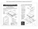
Removing the Mower from its
Packaging
Mowers are normally delivered from the
factory in special packaging - a wooden crate
with a solid bottom.
WARNING!
Handle the transport crate
carefully. Keep the goods as
level as possible.
Use long pallet forks.
8011-549
Mower on its delivery baseplate
English-19
www.mymowerparts.com
For Husqvarna Parts Call 606-678-9623 or 606-561-4983
DELIVERY SERVICING
The baseplate itself stands on a pallet and the whole assembly can be handled using a standard forklift
truck. To keep the goods as level as possible, two people should assist the truck driver. Driving and lifting
must both be performed with care.
Remove the upper part of the crate from the wooden baseplate.
The mower (rear wheels not fitted) is secured to the baseplate by plastic straps and wooden blocks. Certain
components that are to be fitted to the mower, or handed to the purchaser on delivery, are wrapped
separately in plastic bags.
Remove the plastic sheeting covering the mower.
When unpacking the mower, check that there is no transport damage. Any damage is to be reported to the
transport company in the normal way.
The packaging is not to be returned.
Delivery Service
1.
Charge the battery. The mower is
normally delivered with a charged
battery topped-up with electrolyte.
2.
Raise the rear of the mower until it is
clear of the baseplate and the rear
wheels can rotate freely. Hold firmly in
position using blocks or jack stands.
3.
With the valves facing outwards, fit the
rear wheels. Fit and tighten the wheel
nuts on the wheel bolts.
4.
Check and adjust the pressure in all the
tires. The recommended pressure is 1
bar (15 PSI).
8011-503
Fitting the rear wheels
5.
On both motion control levers, remove
the lower bolts and loosen the upper
bolts. Swing the levers to the upright
position. Hand tighten the lower bolts in
the rectangular holes. The levers are
adjusted at a later stage.
6.
Push the levers out into their neutral
slots.
8011-502
Lever mount
English-20
www.mymowerparts.com
For Husqvarna Parts Call 606-678-9623 or 606-561-4983
DELIVERY SERVICING
7.
In the space to the left of the hydraulic
tank, cut the cable tie holding the rod to
the top of the seat. Remove the split
cotter, swing the seat backwards and
connect the rod to the seat. Replace the
split cotter.
Check that the contactor on the cable to
the bottom of the seat is connected.
Swing the seat down and check that it is
held by the catch on the left.
8011-504
Connnecting the rod to the seat
IMPORTANT INFORMATION
Risk of incorrect assembly/fitting
8.
Fit the armrests. Position the armrests
with the greatest possible distance
between them. The bolt heads should be
on the inside (i.e. towards the seat back)
and washers and nuts on the outside.
Armrests, bolts, washers and anti-slip
nuts are packed in a plastic bag
accompanying the mower.
8011-505
Fitting the armrests
9.
Check the engine oil level.
With the mower standing on a flat
surface, check the engine oil level.
Unscrew the dipstick and pull it out. Wipe
the dipstick dry and push it back.
Do not screw the dispstick down.
Pull the dipstick up again and read the oil
level.
8011-501
Checking the engine oil level
English-21
www.mymowerparts.com
For Husqvarna Parts Call 606-678-9623 or 606-561-4983
DELIVERY SERVICING
The oil level must be between the
markings on the dipstick. If the level is
near the “ADD” mark, top up with oil to
the “FULL” mark.
ADD
Oil is topped up via the hole in which the
dipstick sits.
FULL
Use grade SC-SH engine oil with a
viscosity as per the chart below.
The engine (excluding oil filter) holds 1.5
litres of oil.
ADD
FULL
8009-159
Engine dipstick
-20 C
-10 C
0C
10 C
20 C
30 C
40 C
SAE40
SAE30
SAE10W-30/SAE10W-40
SAE5W-20
-4 F
14 F
32 F
50 F
68 F
86 F
104 F
8009-140
Viscosity chart
10. Check the oil level in the hydraulic tank.
The level must be 19 - 25 mm below the
top of the tank. Top up if necessary.
8011-565
Hydraulic tank
11. Adjust the motion control levers.
a.
Set the seat longitudinally in a
comfortable position and swing the levers
into the drive channel.
b.
Hold one of the levers at a comfortable
midpoint and tighten the retaining bolts.
c.
Hold the other lever as far forward as the
first and tighten the bolts.
8011-522
Adjusting the motion control levers
English-22
www.mymowerparts.com
For Husqvarna Parts Call 606-678-9623 or 606-561-4983
DELIVERY SERVICING
WARNING!
Gasoline is highly flammable.
Take great care.
12. Fill the gasoline tanks (unleaded
gasoline with no oil and a minimum
octane rating of 87).
Environment-friendly, acrylate gas , e.g.
Aspen, can be used to good advantage.
8011-550
Fueling
13. Select tank by moving the selector to the
appropriate position.
8011-506
WARNING!
Never run the engine indoors in
confined or poorly ventilated
areas. Exhaust fumes contain
carbon monoxide (poisonous).
Selecting the gasoline tank
14. Connect exhaust fume extraction.
15. Start the engine.
16. Check that there is drive to both wheels.
17. Vent the hydraulic system.
18. Check that, with the motion control levers
in the neutral position, both rear wheels
are stationary.
19. Remove the blocks supporting the back
end.
20. Raise the mower deck to its highest
position.
8011-507
21. Raise the back of the baseplate and
drive the mower forwards and off.
Air relief screw for the hydraulic system
22. Check mower deck settings as per the
instructions (see ”Adjusting Motion
Control Lever Linkages” on page 34).
English-23
www.mymowerparts.com
For Husqvarna Parts Call 606-678-9623 or 606-561-4983
DELIVERY SERVICING
Test Running
Check that the engine will not start with the park brake engaged.
Check that the engine will not start with the blade engagement button pulled out.
Check that the engine will not start without someone sitting on the driver’s seat.
Start the engine.
Check that the engine stops if, with the park brake engaged, a motion control lever is folded inwards (i.e.
across the operator). Test both the left and the right motion control levers.
Check that the engine stops if, with the park brake disengaged, the operator gets up from the driver’s seat.
Check that, with the drive in neutral and the park brake disengaged, the mower does not move on flat
ground. Increase the throttle setting - the mower must still remain stationary.
Check that the park brake operates correctly.
Check that the mower moves straight forwards/backwards when both motion control levers are
simultaneously moved an equal distance forwards/backwards.
Check that the mower turns normally when driving forwards and backwards.
Check that the mower deck operates correctly and that there is no abnormal noise.
Check that engine idling speed is 1,550 ±50 rpm.
Check that the speed regulator gives a maximum engine speed of 2,800 ±75 rpm.
Administration
Fill in the sales certificate and customer
register, etc. Remember to fill in the serial
number on page 4 and to sign the delivery
service in the Operating Instructions.
English-24
www.mymowerparts.com
For Husqvarna Parts Call 606-678-9623 or 606-561-4983
DESIGN AND FUNCTION
Design and Function
General
The Husqvarna ZTH is a compact, ride-on mower specially designed for mowing large areas of grass. It is
operated via two motion control levers and has hydrostatic drive to the rear wheels. Each rear wheel is
driven by an independent hydrostatic drive system comprising a hydraulic pump and a hydraulic motor. The
hydraulic pumps are driven by a belt from the engine’s crankshaft.
The mower is steered by the independent adjustment of the speed and direction of each rear wheel. The
front wheels are free to turn in whichever direction is most suitable.
The mower deck is mounted underneath the mower and is supplied with a side discharge chute as
standard. The range of accessories includes a BioClip kit of guide plates and blades for mounting beneath
the mower deck casing.
8011-591
ZTH ride-on mower
Mower Identification
Each mower is individually identified by the
details given on plate sited between the
battery and the engine.
Reading downwards, the plate gives:
•
The model number
•
The I.D. code.
•
The serial number.
Quote these when ordering spare parts.
8011-593
Mower identification
English-25
www.mymowerparts.com
For Husqvarna Parts Call 606-678-9623 or 606-561-4983
DESIGN AND FUNCTION
The engine identifiers are located on a
barcoded decal. This is sited on the left side
of the crankcase, directly opposite the starter
motor. The decal gives:
•
The engine code.
•
The engine number.
Quote these when ordeing spare parts.
8009-205
Engine identification
The hydraulic pump identifiers are located on
a bardcoded decal. This is sited on the left
side of the pump housing. The decal gives:
•
The pump type code (BDP-10....).
•
The pump serial number.
8011-594
Hydraulic pump identification
The hydraulic motor identifiers are located on
a round, metal plate. This is sited on the end
of the motor housing. The plate gives:
•
The hydraulic motor type code and
model.
•
The hydraulic motor serial number.
8011-595
Hydraulic motor identification
English-26
www.mymowerparts.com
For Husqvarna Parts Call 606-678-9623 or 606-561-4983
DESIGN AND FUNCTION
Engine
Husqvarna’s ride-on mowers for professional users have two-cylinder, air-cooled engines from Kawasaki.
Major engine repairs are not covered in this workshop manual. Users are referred to Kawasaki’s own
manuals. These contain detailed information on the adjustment and repair of the engines. The manuals can
be ordered from authorized service workshops.
The table below shows the information to be quoted when ordering engine manuals:
Model
Kawasaki’s
engine type
Power
Publication
Kawasaki no.
ZTH5223
FH680V-AS15
17.5 kW (23 hp)
99924-2045-03
ZTH6125
FH721V-AS04
18.6 kW (25 hp)
99924-2045-03
When repairing engines, use genuine spare parts only. The warranty will be invalidated if other parts are
used.
Drive and Control
Via a belt, the engine supplies direct, clutchles, drive to two hydraulic pumps. The pumps have axial
pistons.
Each pump feeds oil to a fixed (non-adjustable) hydraulic motor (one by each drive wheel). The rate and
direction of oil flow is steplessly adjusted (via a mechanical linkage) by the motion control levers.
Adjustment is actuated by a swash plate that regulates the stroke length of the hydraulic pistons. The swash
plate is an integral part of each pump. The mower can be made to turn or reverse by controling the rate and
direction of flow to the hydraulic motors. The hydraulic motors control the speed and direction of the drive
wheels. To swing the mower around its center, simply drive one wheel forwards and the other backwards.
Hydrostatic braking occurs whenever there is no flow of oil from the pumps.
Instructions for the repair of the hydraulic pumps are given in the “Hydro-Gear BDP-10A/21L Service &
Repair Manual”.
Brakes
Hydrostatic braking (see “Drive and Control”)
provides brake control when the mower is
being powered by its engine. Putting the
motion control levers in the neutral position
brakes the mower. To move the mower
manually, open the air screws on the
hydraulic pumps. Oil is then circulated by the
hydraulic motors and the machine can be
moved short distances at low speed.
The mower also has a park brake. This
operates on both rear wheels. A brake band
on each rear wheel is engaged by a lever on
the left of the mower operator. The lever and
the brake bands are mechanically linked.
8011-507
Air screw on hydraulic pump
English-27
www.mymowerparts.com
For Husqvarna Parts Call 606-678-9623 or 606-561-4983
DESIGN AND FUNCTION
Mower Deck
WARNING!
The engine must not be started if the operator’s floor plate or any of the guards for
the mower deck’s belt is/are not securely in position.
The blades are driven by a V-belt from the
engine crankshaft (1). The crankshaft has an
electromagnetic clutch. This locks the deck
pulley to the shaft when current is applied to
the clutch (i.e. when the appropriate control
panel switch is operated).
The belt is automatically adjusted by a spring
(2) operating on the pulley (3) attached to the
top of the mower deck casing. Via vertical
shafts, three other pulleys (4,5,7) each drive a
separate blade. Two idler pulleys (6,8) serve
as belt guides. The outermost pulleys are
shielded by removable guards attached to the
top of the mower deck casing. The operator’s
floor plate acts as a guard preventing contact
with the belt and the other pulleys.
8011-580
Belt routing for the mower deck
WARNING!
The mower blades are extremely sharp. To prevent personal injury, wear protective
gloves when handling the blades.
The blades do not require shear pins. Impact protection is provided by the blades skating on their shafts if
they hit an immoveable object.
The discharge chute is on the right side of the mower deck. It is spring-loaded and can be raised.
For mulching, a BioClip kit is available as an accessory. The kit comprises guide plates and BioClip blades.
It is fitted to the underside of the mower deck.
The mower deck is suspended to the bottom of the mower via two backward inclined struts and four
adjustable chains.
Six anti-scalp rollers on the underside of the mower deck prevent the casing catching on the ground.
Cutting height is set by a lever on the right of the operator. Inserting a pin through the holes in the deck
height adjustment plates sets a limit to the downward movement of the lever.
English-28
www.mymowerparts.com
For Husqvarna Parts Call 606-678-9623 or 606-561-4983
REPAIRS
Repairs
Engine
Removing
1.
Close the fuel valve.
2.
Disconnect the positive cable (red) from
the battery.
3.
If necessary, drain the motor oil.
4.
Disconnect the gas and choke wires from
the carburetor.
5.
Disconnect the fuel line (with its filter)
from the fuel pump.
6.
Disconnect the connecting cable (pigtail)
from the frame harness connector at the
side of the starter motor.
7.
Disconnect the cable from the starter
motor.
8.
Disconnect the cables from the ground
bolt in front of the starter motor.
9.
8011-621
Engine assembly
Raise and support the back of the mower
on blocks or similar.
10. Remove the clip holding the oil drain
hose.
11. Remove the deck belt and clutch (see
Electrical System\Mower deck clutch).
12. Loosen the bolt (2) and twist the clutch
tie down (10) aside (see the “Engine
mounts” diagram).
13. Using a square, 1/2" ratchet wrench,
loosen the pump belt. Roll the belt off the
pulley on the engine crankshaft.
14. Remove the four outer bolts in the engine
mounts.
WARNING!
Heavy lift (40.5 kg).
Handle the engine with care.
Place it safely where it cannot
topple over.
8011-606
Engine mounts
15. Lift the motor directly upwards and
secure it in a safe place.
English-29
www.mymowerparts.com
For Husqvarna Parts Call 606-678-9623 or 606-561-4983
REPAIRS
Fitting
1.
When changing engines, transfer the
necessary components to the new
engine.
The chamfered side of the spacer (3) on
the crankshaft above the pump pulley
must face the engine.
The hub collar of the pulley (5) must face
downwards.
2.
Put the four upper engine mount
isolators (22) in the engine bed (small
diameter end in the engine bed hole).
3.
Check that the clutch tie down (10) is not
deformed (straighten if necessary) and
lower the engine into position. The
engine weighs 40.5 kg.
4.
Inserting the spacers (22), washers (28,
21) and bolts (19) from below, fit the
engine mounts. The tightening torque for
the retaining nuts (20) is 110 Nm (80 ft/
lb).
5.
Fit the pump belt on the pulley. Attach the
spring and use a square, 1/2" ratchet
wrench to cancel the force exerted by the
belt tensioner.
6.
Fit the washer (6) and mower deck clutch
(7). Connect the cable to the connector.
The tightening torque for the bolt (9) is 67
Nm (50 ft/lb).
8011-606
Engine mounts
With the bolt (9) tightened, there should
be perceptible play between the clutch
and the clutch tie down (10) when the
clutch flange is turned by hand. Adjust/
twist the tie down and, using the nut (1),
tighten the bolt (2).
Ensure that the cable cannot be
damaged and secure it with a cable tie.
7.
Roll the mower belt into place on the
clutch pulley. Check that the belt is
routed as per the diagram and that it is
not twisted.
8.
Fit the operator’s foot plate.
9.
Fit the clip for the oil drain hose.
10. Connect the 3 cables to the ground bolt.
11. Connect the cable to the starter motor.
8011-580
Belt routing for the mower deck
12. Connect the pigtail to the frame harness.
13. Connect the fuel line to the fuel pump
English-30
www.mymowerparts.com
For Husqvarna Parts Call 606-678-9623 or 606-561-4983
REPAIRS
inlet.
14. Connect and adjust the gas and choke
wires (see below).
15. Check that the oil drain valve is closed
and fill the engine with oil (see Delivery
Servicing\Delivery Service).
16. Connect the positive cable (red) to the
battery’s positive terminal.
17. Open the fuel valve.
Dismantling and Assembling
Adjustments and Specific Repairs
See the Kawasaki Service Manual for the engine and auxiliary systems.
Troubleshooting
See section 8 of the Kawasaki Service
Manual.
The above section contains a troubleshooting guide for the engine and auxiliary systems. It also has
separate troubleshooting instructions for the starter motor.
Adjusting the Throttle Wire
Adjusting Throttle Lever Tension
If there is insufficient throttle lever friction,
throttle settings can alter while the mower is
being operated. This can be corrected via the
lever’s pivot bolt.
1.
Free the control console and pull
forwards.
2.
Tighten the throttle lever’s pivot bolt.
8011-599
Freeing the controle console
Checking and Adjusting the Throttle Wire
Check that the engine responds to the throttle
control and that the correct engine speed is
achieved at full throttle.
If adjustment is necessary, adjust the lower
wire as follows:
1.
Loosen the clamping screw holding the
wire’s outer casing and set the lever to
the full throttle position.
2.
Check that the throttle wire is attached to
the correct hole in the lower lever, see
8011-554
Checking and adjusting the throttle wire
English-31
www.mymowerparts.com
For Husqvarna Parts Call 606-678-9623 or 606-561-4983
REPAIRS
the diagram.
3.
Pull the throttle wire casing to the far
right and tighten the clamping screw.
Checking and Adjusting the Choke
Wire
If the engine produces black smoke or is
difficult to start, the choke wire (upper wire)
may be incorrectly adjusted.
To adjust the choke, proceed as follows:
1.
Release the clamping screw that secures
the wire casing and set the choke control
to maximum choke.
2.
Check that the throttle wire is attached to
the upper lever, see the diagram.
3.
Pull the choke wire casing to the far right
and tighten the clamping screw.
8011-555
Checking and adjusting the choke wire
English-32
www.mymowerparts.com
For Husqvarna Parts Call 606-678-9623 or 606-561-4983
REPAIRS
Fuel tank
Removing
Before removing the tank on the right of the mower, the rear wheel and the bolts holding the oil cooler for
the hydraulics must be removed.
1.
Close the fuel valve (13).
WARNING!
Fire and health hazard.
Avoid spills.
Wipe dry if necessary.
2.
Drain the tank that is to be removed.
Keep the drained fuel in a closed
container.
3.
Remove the hose clamp (5) from the fuel
line (6).
4.
To catch any spills, position a container
below the outlet from the tank to the fuel
line. To ensure no damage is caused,
hold the hose barb (4) with pliers and pull
the fuel line away. Even when the tank is
empty, a small amount of fuel may leak
out.
5.
The tank is fitted to the splashguard by a
bolt and two studs. Remove the bolt (16)
and three nuts (10) - all with washers (8)
and springs (9) - located on the
underside of the splashguard.
6.
Remove the bolt (12) and tank spacer
located on the inside of the splashguard.
7.
Lift the fuel tank (2) away.
8011-607
Fuel tank
Fitting
The fitting procedure is the reverse of the removal procedure.
Working from the underside of the splashguard, tighten each washer (8) spring (9) washer (8) combination
using the appropriate nut (10) or bolt (16). Tighten until the spring starts to compress and then a further 1.5
turns.
English-33
www.mymowerparts.com
For Husqvarna Parts Call 606-678-9623 or 606-561-4983
REPAIRS
Adjusting Motion Control Lever
Linkages
See “Hydraulic system\Hydraulic pump\Adjusting the linkages”.
Adjusting Motion Control Lever
Spring-back
See “Hydraulic system\Hydraulic pump\Adjusting the Reverse Detent Spring”.
Adjusting the Park Brake
Spring
1/8 - 1/4" Space
1.
Raise the rear of the unit and place it on
stable jack stands. Engage the parking
brake and remove both rear tires/wheels.
2.
With the parking brake still engaged,
remove all spring tension by loosening
the spring locknut. Unlock the jam nut
against the yoke and loosen the bolt until
the head is about 1/2 inch away from the
trunnion. Relock the jam nut against the
yoke. Tighten the spring locknut until bolt
head/trunnion gap closes to 1/8 to 1/4
inch.
Yoke
3.
Disengage the parking brake hand lever
and check that the spring is still under
tension. This is important in order to hold
the linkage from going over-center.
Adjusting the park brake
Jam nut
Trunnion
8011-581
4.
Repeat steps 2 and 3 on the opposite
brake band.
5.
If the brake band is making noise while in operation, rattling, squealing, etc, it may be necessary to
readjust the parking brake band.
IMPORTANT INFORMATION
This brake system has been designed as a parking brake and is intended to hold the unit
in place when it is not being operated. It must not be used as an emergency stopping
brake, or brake and linkage damage may occur.
This brake system is not designed to be the only means of holding the unit in place while
transporting in a truck or on a trailer. The unit must be tied down at all times while it is
being transported, or brake and linkage damage may occur
English-34
www.mymowerparts.com
For Husqvarna Parts Call 606-678-9623 or 606-561-4983
REPAIRS
Mower Deck
WARNING!
No work is to be done on the mower deck or belts until the engine has been
rendered incapable of starting. Remove the ignition key or both spark plug cables.
Removing
1.
Drop the deck as far as it will go and lock
the control lever in position with a pin.
2.
Remove the operator’s foot plate.
3.
Remove the deck belt outer guards.
4.
Using a 9/16" socket on the bolt of the
idler pulley, loosen the deck belt. Roll the
belt off the deck pulleys.
5.
Remove the deck’s rear anti-scalp
rollers.
WARNING!
Danger of personal injury (crushed fingers or limbs, etc.).
If the deck height control lever is not secured by a locking pin, the deck will spring
upwards when the chains are released.
6.
Release the four chains from their
mounts on the lift arms (top of chain).
7.
On both sides of the deck, remove the
bolts (17) and pivot pins (50) of the rear
bearings (see the “ZTH mower deck”
diagram).
8.
Pull the deck out.
Fitting
1.
Slide the deck into position under the
mower.
2.
Using two lengths of 2" x 4" (one towards
the edge of each of the deck’s short
sides) support the deck 4" off the ground.
3.
Grease the pivot pins (50) of the rear
bearings with copious amounts of
corrosion preventing grease. Line up the
shaft bearings and slide the pivot pins
into place. Fit the bolts and nuts (17, 5)
holding the pivot pins in place (see the
“ZTH mower deck” diagram).
8011-601
Supporting the deck on lengths of 2” x 4”
English-35
www.mymowerparts.com
For Husqvarna Parts Call 606-678-9623 or 606-561-4983
REPAIRS
4.
Fit the deck’s rear anti-scalp rollers.
5.
Attach the chains to the lift arms.
6.
Fit the belt as per the routing diagram.
7.
Check that the belt is not twisted and that
it runs correctly around all the pulleys.
8.
Check deck height and horizontality as
per “Setting the mower deck”.
9.
Fit the operator’s foot plate.
10. Fit the deck belt outer guards.
8011-580
Belt routing of the mower deck
Spindle Blade Bearings
WARNING!
Wear protective gloves when
working on or with blades.
To remove a blade, undo the retaining bolt
(25).
When fitting a blade, tighten the bolt to 122
Nm (90 ft/lb).
Removing Bearings
1.
Roll the belt off (see “Changing Belts”).
2.
Remove the bolt (28) and the pulley (3).
Lock the pulley using a bolt through the
hole in the pulley and a holding tool.
3.
Raise the mower deck to its highest
position. Lift the front end of the mower
and support it on blocks or similar.
4.
Remove the bolts (12) and nuts (5) and
pull downwards to remove the bearing
and blade.
5.
Separate the blade from its bearing.
Repairing Bearings
If there is too much play, the bearing (44) can
be replaced if the bearing surfaces of the
housing (46) have not been damaged.
8011-618
ZTH mower deck
Pressing downwards, remove the spindle
(41).
If there is extensive damage, replacement of
the complete bearing assembly (2) is
recommended.
To ensure safe transport, the bearing
English-36
www.mymowerparts.com
For Husqvarna Parts Call 606-678-9623 or 606-561-4983
REPAIRS
assembly is supplied with an “O” ring (47) .
The “O” ring must be removed before the
pulley is fitted.
Replacing Bearings
The fitting procedure is the reverse of the
removal procedure.
Tightening torques:
•
Blade bolts 122 Nm (90 lb/ft).
•
Pulley bolts 61 Nm (45 lb/ft).
Sharpening and Balancing Blades
WARNING!
Blades with any cracking must
not be used. Do not straighten
a damaged blade if there is any
danger of crack formation.
•
Remove the blades.
•
Check that the blades do not have cracks
or any other damage. If they do, scrap
them.
•
6012-088
Grinding a blade
Clamp in a screw vice (see diagram) and
file until sharp.
Balancing is as follows:
•
Fix a mandrel (for example) horizontally
in a screw vice (see diagram).
•
Push a blade onto the mandrel and
check that it is evenly balanced. The
diagram shows a blade which needs
adjusting. This blade should be ground at
the edge indicated by the straight arrow.
•
The fitting procerdure is the reverse of
the removal procedure.
The tightening torque for the blade bolts
is 122 Nm (90 lb/ft).
6012-089
Balancing a blade
English-37
www.mymowerparts.com
For Husqvarna Parts Call 606-678-9623 or 606-561-4983
REPAIRS
Setting the Mower Deck
Leveling
1.
Position the mower on a level, preferably
concrete, surface.
2.
Check the pressure in all four tires. This
should be 15 psi.
3.
Raise the mower on lengths of 2" x 4"
placed edgewise under the cutting deck
from front to rear (see diagram).
4.
Place a 0.635 cm (1/4") shim between
the 2" x 4" and the rear edges of the
deck. This will allow the correct down
angle at the front of the deck.
5.
8011-601
Leveling the mower deck
Adjust the four lower chain bolts so that
they are centered in the oblong slots.
IMPORTANT INFORMATION
Ensure that all four bearings suspending
the deck to the mower are tightly bolted to
the frame.
6.
Check that all the chains are equally
tensioned. If they are not, adjust the
appropriate lower chain bolt in its slot.
Adjusting Cutting Height
Raise and secure the deck height lever to the
transport position (6"). Measure from the
cutting edge of the blades to the flat level
surface. The distance should be150 mm (6").
Drop and secure the lever at (for example)
the 2" cutting height. Measure as above. The
distance should be 50 mm (2").
Deck Belt
Check the belt every 75 to 100 hours of
operation. Inspect carefully for large cracks
and significant damage. The small cracks that
arise from normal use do not make it
necessary to change the belt.
Changing Belts
1.
Drop the deck to its lowest position.
2.
Remove the operator’s foot plate.
3.
Remove the outer deck belt guards.
8011-622
Slackening the belt tensioner
English-38
www.mymowerparts.com
For Husqvarna Parts Call 606-678-9623 or 606-561-4983
REPAIRS
4.
Using a 9/16" socket on the bolt of the
idler pulley, loosen the deck belt. Roll the
belt off the deck pulleys.
5.
Roll the belt off the clutch pulley on the
crankshaft.
6.
Remove the old belt.
7.
Fitting the new belt is the reverse of the
procedure given above. Ensure that belt
routing is as per the accompanying
diagram.
8.
Check that the belt is not twisted and that
it runs correctly around all the pulleys.
8011-580
Belt routing for the mower deck
Belt Tensioning Assembly
The belt is automatically tensioned by a
spring (18). To cancel the force of the spring ,
use a 9/16" socket on the bolt (33) when
removing or fitting the belt.
Check that there is no abnormal noise
indicating that the idler pulley is loose on its
shaft. If it is loose, tighten the bolt (33) or
change the idler pulley.
Check that the idler arm is not loose on its
bearing. If it is, tighten the nut (34) or change
the bushing (38).
8011-617
Belt tensioning assembly
English-39
www.mymowerparts.com
For Husqvarna Parts Call 606-678-9623 or 606-561-4983
REPAIRS
Hydraulic Pump Belt
Check the belt every 75 to 100 hours of
operation. Inspect carefully for large cracks
and significant damage. The small cracks that
arise from normal use do not make it
necessary to change the belt.
Changing Pump and Deck Belts
1.
Drop the deck to its lowest position.
2.
Remove the operator’s foot plate.
3.
Remove the outer deck belt guards.
4.
Using a 9/16" socket on the bolt of the
idler pulley, loosen the deck belt. Roll the
belt off the deck pulleys.
5.
Roll the belt off the clutch pulley on the
crankshaft.
6.
Loosen the bolt (2) and twist the clutch
tie down (10) aside (see the “Engine
mounts” diagram).
7.
Using a square, 1/2" ratchet wrench,
slacken the pump belt and roll it off the
pulley for one of the hydraulic pumps.
8.
Remove the old belt.
9.
Fit the new belt on the crankshaft pulley.
8011-623
Slackening belt tension
10. Swing the idler pulley towards the engine
and fit the belt.
11. Fit the belt around the pulley on the right
(looking upwards from below the mower).
12. Attach the spring and use a square, 1/2"
ratchet wrench to cancel the force
exerted by the belt tensioner.
13. Fit the belt around the left pulley (looking
upwards from below the mower).
14. Check that the belt is not twisted and that
it runs correctly around all the pulleys.
15. Check that there is perceptible play
between the clutch and the clutch tie
down (10) when the clutch flange is
turned by hand (see the “Engine mounts”
diagram). Adjust/twist the tie down and,
using the nut (1), tighten the bolt (2).
8011-624
Belt routing for the hydraulic pumps
16. Fit the deck belt. Check that the belt is
not twisted and that it runs correctly
around all the pulleys.
17. Fit the operator’s foot plate.
18. Fit the outer deck belt guards.
English-40
www.mymowerparts.com
For Husqvarna Parts Call 606-678-9623 or 606-561-4983
REPAIRS
Pump Belt Tensioning Assembly
The belt is automatically tensioned by a
spring (37). To cancel the force of the spring
when removing or fitting the belt, use a 1/2"
ratchet wrench in the square hole in the idler
arm (45).
Check that there is no abnormal noise
indicating that the idler pulley is loose on its
shaft. If it is loose, tighten the bolt (42) and
the set screws (41), or change the bushing
(44).
Check that the idler arm is not loose on its
bearing. If it is, tighten the bolt (49) or change
the bushing (47).
8011-616
Pump belt tensioning assembly
Front Wheel Bearings
Dismantling
1.
Remove the grease cap (26).
2.
Raise and support the front of the mower
on blocks or similar.
3.
Remove the cotter pin (30).
4.
Remove the castle nut (27) and, pulling
downwards, remove the front fork.
5.
Remove the upper bearing (28).
6.
Taking great care not to damage the seal
(31), use a hammer and a suitable rod
(or similar) to knock the lower bearing out
in a downwards direction.
8011-619
Front wheel bearing
Assembling
The assembly procedure is the reverse of the
dismantling procedure.
Lubricate the bearings with ball bearing
grease.
Taking great care not to damage it, tap the
seal into position.
Adjust the castle nut (27) until there is zero
play in the bearings. Loosen the castle nut to
the nearest hole and fit the cotter pin.
English-41
www.mymowerparts.com
For Husqvarna Parts Call 606-678-9623 or 606-561-4983
REPAIRS
English-42
www.mymowerparts.com
For Husqvarna Parts Call 606-678-9623 or 606-561-4983
ELECTRICAL SYSTEM
Electrical System
Troubleshooting
See the “Troubleshooting” section towards the back of this manual.
Wiring Assembly
The diagram below shows the structure of the electrical system.
A. To the engine ground bolt
B. To the solenoid
C. To the electric clutch
D. To the pigtail
E. To the park brake
F. To motion control lever
G. To the seat
H. Console harness
J. Frame harness
8011-584
ZTH electrical system
To connect the engine to the frame harness (13), there is a pigtail. This plugs into connector “D” (see
diagram above). The Kawasaki pigtail is illustrated below.
Vio = Violet
Wht = White
Gra = Gray
8011-587
Kawasaki pigtail
English-43
www.mymowerparts.com
For Husqvarna Parts Call 606-678-9623 or 606-561-4983
ELECTRICAL SYSTEM
The console harness (1) connects the console controls to the frame harness.
Blk = Black
Blu = Blue
Gra = Gray
Grn = Green
Pur = Purple
Wht = White
Yel = Yellow
A
B
C
D
E
F
8011-629
ZTH console harness
English-44
www.mymowerparts.com
For Husqvarna Parts Call 606-678-9623 or 606-561-4983
ELECTRICAL SYSTEM
There are two connectors connecting the frame harness (13) to the console harness (1).
Blk = Black
Blu = Blue
Gra = Gray
Grn = Green
Pur = Purple
Wht = White
Yel = Yellow
8011-628
ZTH frame harness
The engine pigtail (page 43) plugs into the “Engine Pigtail” socket of the frame harness.
English-45
www.mymowerparts.com
For Husqvarna Parts Call 606-678-9623 or 606-561-4983
ELECTRICAL SYSTEM
Battery
The battery is maintenance-free and the cells are sealed. Breaking the seal invalidates the warranty. To
avoid exposing the battery terminals to dangerous stress, use two wrenches when connecting or
disconnecting the battery cables.
WARNING!
The battery contains corrosive acid. Wear goggles. Do not tip the battery over.
The battery gives off explosive fumes. Keep it away from all naked sparks and
flames. Never smoke in the vicinity of the battery.
Never let children or untrained staff handle or work on the battery.
Procedures in the Event of Acid Contact
External: Drench with running water.
Internal: Drink copious quantities of water or milk. See a doctor as soon as possible.
Eyes: Drench with running water. See a doctor as soon as possible.
Fuses
Refer to the “ZTH electrical system” diagram.
The fuses (23, 24) plug into a holder on the
left of the hydraulic tank. They are of the flat
pin type commonly used in automobiles.
There are two active fuses and sockets for
two spares.
Fuse rating and function (working along the
holder from right to left) is:
•
20 A, main fuse.
•
7.5 A, deck clutch.
•
Socket for spare fuse.
•
Socket for spare fuse.
8011-596
Fuses
English-46
www.mymowerparts.com
For Husqvarna Parts Call 606-678-9623 or 606-561-4983
ELECTRICAL SYSTEM
Relays
Refer to the “ZTH electrical system” diagram.
The relays (22) plug into a holder under the
seat (on the left). The three relays are
identical and can be plugged into any of the
sockets in the holder.
Relay function (working along the holder from
right to left) is:
•
Brake relay
•
Run relay
•
Start relay
Removing
Pull relays directly upwards. If necessary,
carefully work a screwdriver under the relay
and lever upwards.
8011-597
Relays
Fitting
The relays have an asymetric pin pattern and will fit into the sockets in one way only. Press each relay down
until the body contacts the holder.
Starter Motor Contactor
Changing
1.
Disconnect the cable connecting the
battery to the chassis. To avoid
damaging the battery terminals, use two
wrenches.
2.
Pull the cables off the contactor.
3.
Remove the contactor (the nuts are
under the frame plate).
4.
Position the new contactor so that the pin
for the control cable is towards the
chassis wall. The black cable connects to
the front binding screw.
5.
Connect the control cable (yellow) to its
pin.
6.
Connect the wires to to the battery and
starter motor as shown in the diagram.
Replace the connector guards.
7.
Connect the cable between the battery
and the chassis.
8011-598
Starter motor contactor
English-47
www.mymowerparts.com
For Husqvarna Parts Call 606-678-9623 or 606-561-4983
ELECTRICAL SYSTEM
Ignition and Start Switch
Refer to the “ZTH electrical system” diagram.
Changing
1.
Free the control console and pull
forwards.
2.
Disconnect the wires at the back of the
ignition switch (10).
3.
Remove the ignition key and the rubber
cap (20).
4.
Remove the nut (19) and the ignition
switch (10).
5.
Thread the toothed plate connector onto
the throat of the new ignition switch.
Feed the switch into the console from the
rear. Turn the switch so that the single pin
faces towards the blade switch.
6.
Start the nut (19) off on its thread and
twist the switch to the correct position in
the console panel. Try the key in the
switch and then tighten the nut.
7.
Remove the key and fit the rubber cap
(20). Reinsert the key.
8.
Reconnect the wires at the back of the
ignition switch.
9.
Refit the control console.
8011-599
Freeing the control console
Hour Meter
Refer to the “ZTH electrical system” diagram.
Changing
1.
Free the control console and pull forwards.
2.
Disconnect the wires at the back of the hour meter (12).
3.
Prise the catches apart and remove the hour meter’s locking plate.
4.
Pull the hour meter out of the console panel.
5.
Ensuring that the numbers are turned to the correct position to be seen by the operator, insert the new
hour meter in the console panel.
6.
Fit the locking frame (push in manually and check that the catches have fastened).
7.
Connect the two violet wires to the right pin and the black to the left.
8.
Refit the control console.
English-48
www.mymowerparts.com
For Husqvarna Parts Call 606-678-9623 or 606-561-4983
ELECTRICAL SYSTEM
Blade Switch
Refer to the “ZTH electrical system” diagram.
Changing
1.
Free the control console and pull forwards.
2.
Disconnect the wires at the back of the switch (11).
3.
Push in the plastic catch on the switch’s short side and draw the switch out through the console panel.
4.
With the plastic catch and two contact pins facing upwards, push the new switch into the console panel
unitl it is correctly seated.
5.
Reconnect the wires at the back of the switch.
6.
Refit the control console.
Mower Deck Clutch
Measuring the Supply Voltage
See the “Troubleshooting” section towards
the back of this manual.
Measuring Coil Resistance
See the “Troubleshooting” section towards
the back of this manual.
Troubleshooting Guide
See the “Troubleshooting” section towards
the back of this manual.
8011-592
Deck clutch
Removing
1.
Drop the deck to its lowest position.
2.
Remove the operator’s foot plate.
3.
Using a 9/16" socket on the bolt of the
idler pulley, loosen the deck belt. Roll the
belt off the deck pulleys.
4.
Roll the belt off the clutch pulley on the
crankshaft.
5.
Disconnect the cable feeding the clutch.
The connector is located next to the left
engine mount.
6.
Remove the bolt (9) and the lock washer
(8).
7.
Remove the clutch (7) and the spacer
(6).
8011-6022
Loosen the deck belt
English-49
www.mymowerparts.com
For Husqvarna Parts Call 606-678-9623 or 606-561-4983
ELECTRICAL SYSTEM
Fitting
The fitting procerdure is the reverse of the removal procedure.
Pay particular attention to the following:
•
The tightening torque for the bolt (9) is 67 Nm (50 ft/lb).
•
With the bolt (9) tightened, there should be perceptible play between the clutch and the clutch tie down
(10) when the clutch flange is turned by hand. If necessary, adjust/twist the tie down.
•
Ensure that the cable cannot be damaged and secure it with a cable tie.
Motion Control Switches
These micro switches are difficult to access. By pulling the control console forwards, it is possible to change
the right switch without any other major dismantling. However, this does require two people. When
changing the left switch, the tubular shafts (31, 33) of the motion control levers must be lowered or
removed. The procedure for doing this is detailed below and may also be used for the right switch.
8011-589
Hydraulic pump linkages
English-50
www.mymowerparts.com
For Husqvarna Parts Call 606-678-9623 or 606-561-4983
ELECTRICAL SYSTEM
Removing
1.
Swing the seat completely out of the way.
2.
Release the mechanical link between the left park brake and the brake lever.
3.
Release the dampeners (23) and springs (17) from the tubular shafts (31, 33) by removing the bolts
(16) - each with two nuts (22) - spacers (21) and washers (11).
4.
Release the front end of the ball joints (32) from the tubular shafts (31, 33) by removing the bolts (14),
nuts (22) and washers (11).
5.
Remove the control lever by removing the bolts (3) and spring washers (4).
6.
Remove the bolt to the park brake arm (on the right side of the park brake shaft). Remove the arm and
the released washers from the park brake shaft.
7.
Pull out the park brake shaft and lever to the left. When the shaft is pulled out, the tubular shafts, first
(33) and then (31), will be freed.
8.
Disconnect the cable connection to the switch and remove the tubular shaft.
9.
Remove the switch from the tubular shaft.
Fitting
The fitting procedure is the reverse of the removal procedure.
Pay particular attention to the following:
•
Check and position the switches before fitting the tubular shaft.
•
Position the switches so that there is a click when the inner flat surface of the arm continuation shaft (5)
passes over the outside corner of the tubular shaft’s lever mount.
•
Check the setting of the linkages (see Hydraulic System\Hydraulic Pump\Linkage Adjustment).
•
Check the setting of the reverse detent spring (see Hydraulic System\Hydraulic Pump\Reverse Spring
Detent Adjustment).
Park Brake Interlock Switch
Refer to the “ZTH electrical system” diagram.
Changing
1.
Disengage the park brake.
2.
Drop the deck to its lowest position.
3.
Remove the bolts (9). The tapped plate
(8) is freed when the switch is loosened.
4.
Separate the connector from the switch
(7). Pull it directly upwards.
5.
Push the connector onto the new switch
(there is only one way for the parts to
mate).
6.
Using the bolts (9) and tapped plate (8),
fasten the switch securely to its bracket.
7.
Check that the start interlock functions
correctly.
8011-600
Park brake interlock switch
English-51
www.mymowerparts.com
For Husqvarna Parts Call 606-678-9623 or 606-561-4983
ELECTRICAL SYSTEM
Welding
The following applies to arc, MIG, TIG and all other electrical welding methods.
IMPORTANT INFORMATION
When performing electric welding on the
mower, take all necessary precautions to
prevent damage to the electrical system.
The engine’s ignition system has sensitive electrical components. Electrical welding must not, therefore, be
carried out on the engine. Remove the component to be welded (e.g. the muffler) or the ignition system.
Before carrying out welding on any other part of the mower:
1.
Remove the battery cables.
2.
Disconnect the connector between the engine pigtail and the frame harness.
3.
Connect the welding earth lead as near as possible to the point of welding.
English-52
www.mymowerparts.com
For Husqvarna Parts Call 606-678-9623 or 606-561-4983
HYDRAULIC SYSTEM
Hydraulic System
Hydraulics Hygiene
If they are to operate well, hydraulic systems must be kept free from all impurities. During operation,
particles that can cause both wear and malfunction are generated inside hydraulic systems. To separate
these particles from the hydraulic fluid, filters are used. Filters are dimensioned to cope with particles
developed within the system. If impurities enter from outside, filters tend to clog quickly and become
ineffective. Any dirt entering a hydraulic system accelerates the production of further impurities. A vicious
circle arises; there is much disruption and a lot of time is lost in cleaning.
The particles causing most damage are those which are of roughly the same size as the play between the
moving parts in system components. Normal play in pumps and valves is from 3 - 5 µm and upwards (1 µm
= 0.001 mm). It should be noted that a particle measuring 40 µm can only just be seen by the naked eye.
The main impurities generated in system operation are:
•
Wear particles (mainly from components with moving parts, e.g. pumps and hydraulic motors).
•
Dust entering the hydraulic oil tank via air vents.
•
Water formed by condensation (water vapor enters with air from outside).
•
Particles of dirt entering the system via moving piston rods, etc.
•
Sediments, etc. produced by the breaking down of the hydraulic oil.
•
Corrosive matter produced in the system as a result of oil not being changed in time. Old oil tends to be
rich in water and other aggressive substances.
•
Dirt entering the system during service or repair work, e.g.:
- Contamination during the changing or topping-up of oil.
- Dust in the workshop.
- Sealing agents and similar.
- Dirt from storage and handling prior to fitting.
- Fibers from rags, filters, etc.
- Dirt from parts not cleaned prior to dismantling.
- Dirt and dust entering the system from contaminated protective plugs.
Especially if the system is not regularly used, even microscopic quantities of water will accelerate the
rusting of ground and polished surfaces. This hastens the formation of sediments that can clog filters and
give rise to circulation and cavitation problems in hydraulic pumps.
Minute fibers and threads from cleaning rags or clothing can form fluff which will obstruct nozzles and other
narrow apertures. The fibers themselve do not cause significant damage, but the clogging they generate
greatly accelerates component wear.
Every particle of dirt in hydraulic systems acts as a grinding agent. Abrasion is increased, more impurities
are produced and permanent damage is caused. Particle quantity increases every time work is done on
hydraulic systems. Although most particles will have been trapped by the filters after a few hours operation,
it is obviously good practice to avoid all unnecessary opening of hydraulic systems, even if carried out by
professionals.
English-53
www.mymowerparts.com
For Husqvarna Parts Call 606-678-9623 or 606-561-4983
HYDRAULIC SYSTEM
Hydraulic Oils
The oil is as important as any other part of the hydraulic system. It has been shown that 70% of all
problems with hydraulics are due either to the use of unsuitable oil grades or filling/topping-up with
contaminated oil.
Contamination from outside is responsible for by far the greater part of the impurities in the oil in hydraulic
systems.
Correct Oil Leaks
Cavitation from injested air can cause internal hydraulic pump and wheel motor damage. Air can enter the
system anywhere there is an oil leak. Therefore it is very important that oil leaks be repaired immedately.
Keep Hydraulic Oil Clean
Dirt and other forms of contamination are the greatest enemies of hydraulic systems. Long system life and
high efficiency very much depend on hydraulic oil being kept in good condition. Use only the grade of oil
stated in the lubrication chart. Make sure that hydraulic oil is inspected at regular intervals and that levels
are kept topped-up.
All high-quality hydraulic oils are supplied in clean containers and have been filtered as free from impurities
as possible. It is when the containers are opened or stored that problems arise. Do not open a container
before the area around the cap, seal or similar has been wiped clean of all dust, dirt, fibers and water. Any
other container, funnel or hose used when filling the hydraulic system must be clean.
Work Methods
Cleanliness is also vital for any components being removed from or fitted to a hydraulic system. However, it
must be borne in mind that used components sent to a workshop will often be specially inspected and/or
tested. Such components should be dispatched in the condition they were prior to removal. Otherwise, the
true reason for the fault may be difficult to ascertain and testing may give false results. Furthermore,
returned components that have been cleaned may mistakenly be presumed to be free from defect and sent
back without the appropriate action being taken.
The following are suggested as routine steps when working on hydraulic systems:
1.
Perform general cleaning as necessary.
2.
Protect the point/area where the repair is to be carried out from dust and other impurities in the air.
Plastic covers and the suchlike can be used.
3.
Clean thoroughly using white spirit or an equivalent. It is not sufficient to clean only those parts
directly affected. Places from where dirt can fall onto the work point must also be cleaned. The
same applies to any tools used at the site of the intervention. Clean with a suitable brush, wipe
with a rag and repeat if necessary. Finally, spray the site, hose connections, etc. with clean white
spirit.
4.
Fit suitable protector plugs/caps immediately after removing a hose or pipe. Components (even
those being replaced), hoses, pipes, etc. should all be suitably protected.
5.
If they are not exchanged for new, all old pipe connector parts must be cleaned with fresh white
spirit and then blown with compressed air before refitting.
6.
Maintain strict hygiene when measuring pressures. Before joining them, spray both parts of quick
couplings with white spirit. Ensure that any protective plugs/caps are clean before they are used
again.
English-54
www.mymowerparts.com
For Husqvarna Parts Call 606-678-9623 or 606-561-4983
HYDRAULIC SYSTEM
ZTH Hydraulic System
8011-588
ZTH hydraulic system
The hydraulic pumps are controlled (via mechanical links) by the motion control levers.
8011-589
Hydraulic pump linkages
English-55
www.mymowerparts.com
For Husqvarna Parts Call 606-678-9623 or 606-561-4983
HYDRAULIC SYSTEM
Hydraulic Tank
Draining
1.
The drain cap (29) is located on the
underside of the tank in the front left
corner (see the “ZTH hydraulic system”
diagram). Drained hydraulic oil must be
handled in accordance with the
regulations governing the disposal of
waste oil. Do not put drained oil back into
the system.
2.
It is not necessary to drain the entire
hydraulic system when performing
scheduled hydraulic system oil changes.
Change only the oil in the tank.
3.
Anytime the hydraulic oil is changed, the
oil filter should also be changed.
8011-590
Hydraulic tank drain cap
Filling
Fill the tank with clean oil direct from the
manufacturer’s container. For oil type, refer to
the hydraulic tank decal or the lubrication
chart. The use of non-approved oils can
invalidate the warranty.
The level must be around 19 - 25 mm (3/4" 1") below the top of the tank. Vent the system
using the air screws on the hydraulic pumps
and top-up as necessary.
Removing
1.
Drain the hydraulic tank as above.
2.
Disconnect the 7" tube (25) and “O” ring (33) from the tank.
3.
Disconnect the hose (27) and “O” ring (33) from the tank.
4.
Remove the bolts (10) - nuts located beneath the bracket - and their washers (13). Lift the tank
away.
Fitting
The fitting procedure is the reverse of the removal procedure.
Use new “O” ring flares.
English-56
www.mymowerparts.com
For Husqvarna Parts Call 606-678-9623 or 606-561-4983
HYDRAULIC SYSTEM
The Cooler for the Hydraulic System
Removing
1.
Remove the right rear wheel.
2.
To eliminate any excess pressure, remove then replace the hydraulic tank cap.
3.
Loosen the hose clamps (16) but leave the hoses attached to the cooler.
4.
Remove the bolts (14), spacers (15) and nuts (12).
5.
Hold the bottom of the cooler higher than the hydraulic tank and disconnect the hoses (27, 28)
from the cooler.
Fitting
The fitting procedure is the reverse of the removal procedure.
Hydraulic Filter
Use genuine Husqvarna filters only. The use of pirate parts can invalidate the warranty.
Changing Filters
When changing the oil in the hydraulic tank, change the filter also. Dispose of the used filter in accordance
with the environmental regulations relating to engine oil filters.
An oil filter chain may be used for removal but not for fitting.
1.
Screw the filter (3) from the filter head (4) - refer to the “ZTH hydraulic system” diagram.
2.
Smear the new filter’s gasket with clean hydraulic oil.
3.
Screw on the new filter until the gasket contacts the filter head.
4.
Manually turn the filter a further one and a half turns.
Removing
1.
Drain the hydraulic tank as per the instructions given above.
2.
Disconnect the hoses (25, 26) and “O” rings (33) from the filter head (4).
3.
Remove the bolts (10) and washers (11). Remove the entire filter unit.
Fitting
The fitting procedure is the reverse of the removal procedure.
Use new “O” ring flares.
Hydraulic Lines
Two types of hydraulic lines are used - high pressure hoses and pipes. For pipes (earlier mower models),
the fitting instructions given below apply (they do not need to be observed for mowers with hyrdaulic hoses
between pumps and motors).
English-57
www.mymowerparts.com
For Husqvarna Parts Call 606-678-9623 or 606-561-4983
HYDRAULIC SYSTEM
Fitting
IMPORTANT INFORMATION
Pipes between hydraulic pumps and hydraulic motors must not be subjected to bending or
compression. To avoid pipe fatigue and the resultant leaks and fractures, the fitting
procedures below must be observed.
1.
Clean the surfaces mating pumps and motors to their mounts.
2.
Bolt the hydraulic pump loosely into place - it must still be possible to move the pump.
3.
Bolt the hydraulic motor loosely into place - it must still be possible to move the motor.
4.
Using new “O” rings (34), and only hand tightening the fittings at either end, connect the pipe
between pump and motor.
5.
Tighten the hydraulic pump bolts.
6.
Tighten the hydraulic motor bolts.
7.
Tighten the pipe fittings to a torque of 41 Nm (30 ft/lb).
Hydraulic Pump
Removing
1.
Drain the hydraulic tank as per the instructions given above.
2.
Raise the mower and support on blocks or jack stands.
3.
Remove the rear wheel on the side with the faulty pump.
4.
Using a swivel-jointed socket handle, hold the idler pulley so that the belt can be rolled off the
pulley beneath the pump (see “Changing belts”).
5.
Loosen the two lock screws holding the pump pulley and remove it from its shaft.
6.
Clean as set out in the instructions.
7.
Remove the hydraulic lines (21, 22 or 23, 24) and “O” rings (34) from both pump and motor.
8.
Be careful not to damage the cooler when working on the right hydraulic pump. Release the ball
joint (10) from the pump lever (12) - refer to the “Hydraulic pump linkages” diagram.
9.
Disconnect the hose (28) and “O” ring (33) from the pump.
10. Disconnect the hose (26) and “O” ring (33) from the pump.
11. Remove the pump’s retaining bolts and lift it away.
Dismantling and Assembling
Refer to Hydro-Gear Service Manual for Bantam Duty Pump models 10A and 21L.
Fitting
The fitting procedure is the reverse of the removal procedure.
Use new “O” rings.
Pay particular attention to the following:
•
Fit hydraulic pipes as per the instructions under “Hydraulic Lines”.
English-58
www.mymowerparts.com
For Husqvarna Parts Call 606-678-9623 or 606-561-4983
HYDRAULIC SYSTEM
•
Ensure that the pump pulley aligns with the crankshaft pulley and the pulley for the other pump.
•
Ensure, on both sides, that the link between the motion control lever and the hydraulic pump is
correctly adjusted.
•
Vent the hydraulic system before operation.
Linkage Adjustment
WARNING!
Ensure the mower is securely supported on blocks or jack stands.
Keep hands, feet and clothing away from rotating tires.
This adjustment must be made with the rear wheels rotating. Raise the rear of the mower and support it
securely on blocks or jack stands so that the wheels are free to rotate.
1.
Remove the seat rod so that the seat can swing down onto the frame.
2.
Tilt the seat forward and, to engage the seat safety switch, place a length of 2" x 4" between the foot
plate and the center of the seat.
3.
Loosen the jam nuts (20) directly behind each ball joint (10, 32) on the pump control links. These
links can now be rotated using the other nuts (9). The jam nuts have a left-hand thread.
4.
Start the engine (the park brake must be engaged and the motion control levers in the neutral
slots). Run the engine at approximately half throttle.
5.
Release the park brake so that the rear wheels can rotate.
6.
Working on one side at a time, put the motion control lever into the neutral position in the drive
channel. Adjust the motion control linkage by turning the two nuts (9) in the proper direction. Turn
these nuts far enough to just stop the wheel rotating.
7.
Move the motion control lever forward, then into the neutral position and then into the neutral slot.
The wheel must stop completely at this point.
8.
Now move the motion control lever into the reverse position and release it. The lever should return
to neutral on its own. If not, the reverse spring detent must be adjusted, check below.
9.
Tighten the jam nuts directly behind each ball joint (10, 32).
10. Adjust the linkage on the other side in the same way.
11. Reattach the seat rod to the seat.
Reverse Spring Detent Adjustment
1.
Stop the engine and remove the key.
2.
Pull the motion control lever back to the reverse position and then release it. The lever should
spring back and stop centrally in line with the neutral slot (i.e. it should be possible to move the
lever directly back to the locked neutral position without touching the sides of the slot).
3.
If adjustment is required, move the seat to the back of its slide rails before tilting it forward and
removing the rod from the seat frame. Swing the seat down onto the frame.
4.
Sufficient to allow the bolt to slide in its slot, loosen the nut (27) fastening the spring (17) to its
upper mount.
5.
Swing the motion control lever out into the neutral slot. While it is there, pull it against the back
face of the neutral slot.
English-59
www.mymowerparts.com
For Husqvarna Parts Call 606-678-9623 or 606-561-4983
HYDRAULIC SYSTEM
6.
Holding the lever, adjust the spring by sliding the bolt (37) in the slot to remove all the slop.
Retighten the bolt.
7.
Check the adjustment by pulling the motion control lever back to the reverse position and
releasing it.
8.
If necessary, make the same adjustment on the other side.
9.
Reattach the seat rod to the seat frame.
Hydraulic Motors
Removing
1.
Drain the hydraulic tank as per the instructions given above.
2.
Raise the mower and support on blocks or jack stands.
3.
Remove the rear wheel on the side with the faulty motor.
4.
Remove the cotter pin and hub nut. Using an extractor if necessary, pull the hub off the axle.
5.
Remove the park brake as a single unit.
6.
Clean as set out in the instructions.
7.
Disconnect the hydraulic lines (21, 22 or 23, 24) and “O” rings from both the pump and the motor.
8.
Remove the hydraulic motor from its bracket.
Dismantling and Assembling
Refer to Parker Hydraulics TorqlinkTM Service Procedure for TE Hydraulic Motors.
Fitting
The fitting procedure is the reverse of the removal procedure.
Use new “O” rings.
Pay particular attention to the following:
•
Fit hydraulic pipes as per the instructions under “Hydraulic Lines”.
•
The tightening torque for the hub nut is 122 Nm (90 ft/lb). After tightening, align the nut with the cotter
pin hole.
•
Adjust the park brake as set out in the instructions.
•
Vent the hydraulic system before operation.
English-60
www.mymowerparts.com
For Husqvarna Parts Call 606-678-9623 or 606-561-4983
TROUBLESHOOTING
Troubleshooting
Engine
Check section 8 of the Kawasaki Service Manual.
The above section contains a troubleshooting guide for engine and auxiliary systems. It also has a special
section on troubleshooting the starter motor.
Wiring Harness
•
Symptom: The starter motor works but the engine does not turn over.
Suggested procedure:
1.
Check the fuel level and the position of the fuel valve lever.
2.
If OK, disconnect the hose, hold the end in a container and crank the engine. If no fuel comes out,
the fuel pump is faulty or the line is blocked. If fuel does come out;
3.
Remove the air filter cover and air filter. The fuel valve can be seen in front of the carburetor. With
the seat switch depressed, hold a finger against the valve and turn the ignition switch to RUN. A
sharp click will be felt if the valve opens (the carburetor will then be getting fuel). If not;
4.
Disconnect the main harness from the engine. Locate the red and violet wires in the main harness
connector. Attach the red (+) lead from a voltmeter to this connector, and ground the black (-) lead
to the mower chassis. With an operator in the seat and the ignition turned to RUN, the voltmeter
should register 12 volts. If it does, the fuel valve is faulty. If there is no voltage, the problem may be
in the harness wires, the connectors or the ignition switch.
•
Symptom: The starter motor does not work.
Suggested procedure:
1.
Check that the brake lever is in the on position, that the blade engagement switch is pushed in,
that the motion control levers are in the neutral slots and that there is someone on the driver’s
seat. If all correct;
2.
Check the 20-amp fuse. If OK;
3.
Check the battery for charge (should be 12 to 13 volts) and that the battery cables are making
good contact at both ends. If OK;
4.
With all levers and switches properly positioned for start and an operator on the seat, hold index
finger and thumb against the start relay, and turn the ignition switch to RUN. A sharp click should
be felt in the relay. If not, change the relay and try again. If a click is felt;
5.
Check that all harness connections to the various switches and the engine are properly
connected. If all OK;
6.
Disconnect the yellow lead from the starter’s contactor; attach the red (+) lead of a voltmeter to
this wire, and ground the black (-) lead to the mower chassis. With all levers and switches properly
positioned for start and an operator on the seat, turn the ignition to RUN. The voltmeter should
read 12 to 13.5 volts. If there is no voltage, the harness may have a broken wire, a connection in a
cable connector may be damaged or a switch broken/incorrectly set.
•
Symptom: The ignition fuse blows with the ignition switch at RUN, but does not blow if the engine
connector is disconnected.
Suggested procedure:
1.
With engine connector connected, disconnect the seat and brake switches and the blue and violet
lead from the hour meter. Does the 20-amp ignition fuse still blow when the ignition is now turned
English-61
www.mymowerparts.com
For Husqvarna Parts Call 606-678-9623 or 606-561-4983
TROUBLESHOOTING
to RUN?
2.
If yes, the problem is probably in the engine harness, engine components or ignition switch.
Disconnect the fuel valve. If the fuse does not blow, the problem is probably in the fuel valve.
3.
If, from point 1 above, the fuse does not blow, reattach the hour meter connectors. If the fuse
blows, the hour meter is probably faulty.
4.
If the hour meter is OK, reconnect the brake switch and pull the brake on. If the fuse holds,
reconnect the seat switch and turn the ignition to RUN.
5.
If the fuse holds, remove and then replace the relays one at time and try again. A blown fuse here
indicates that the relay is faulty.
6.
If it has been established that the problem is in one of the safety interlock circuits, that the battery
is delivering 12 volts and that the main fuse is OK, but that the engine will not turn over, the brake
relay can be easily tested as set out below.
IMPORTANT INFORMATION
Disconnecting the brake relay bypasses that part of the interlock system which
prevents the mower moving with the brake on.
Engage the brake, disconnect the brake relay and attempt to start the engine. If the engine now
turns over and the main fuse holds, the brake relay is probably faulty.
•
Symptom: Clicking under the console; the engine runs poorly and surges.
Suggested procedure:
1.
Disconnect the hour meter. If the symptoms disappear, replace the hour meter.
English-62
www.mymowerparts.com
For Husqvarna Parts Call 606-678-9623 or 606-561-4983
TROUBLESHOOTING
Clutch
•
Measuring clutch coil resistance.
1.
Turn the engine and PTO switch off.
2.
Disconnect the clutch at the clutch
connector.
3.
Set the meter to read ohms.
4.
Connect the meter leads to the clutch.
5.
Check the meter reading.
CMS-175 (237 Nm) = 2.45 - 2.71 Ω.
CMS-200 (271 Nm) = 1.74 - 1.93 Ω.
The values above are at 23°C (68°F).
If the reading falls within the acceptable
range, measure the supply voltage at the
clutch. If not, replace the clutch.
1. Connector
Ω. Ohmmeter
8011-567
Measuring resistance
•
Measuring the supply voltage at the
clutch.
1.
Turn the engine off.
2.
Connect the meter leads at the clutch
connector.
3.
Set the meter to read volts.
4.
Ensure that the wires will not become
entangled in the rotating parts of the
clutch.
5.
Start the engine and engage the PTO
switch.
6.
Measure the voltage across the leads at
the connectors.
7.
8.
1. Connector
V. Voltmeter
The voltage should be 12 - 14 volts DC. If
the clutch still fails to operate, replace the
clutch.
If voltage is not within the 12 - 14 volt
range, measure input voltage and output
voltage at the clutch switch. Any drop in
voltage is unacceptable.
8011-568
Voltage measurement
English-63
www.mymowerparts.com
For Husqvarna Parts Call 606-678-9623 or 606-561-4983
TROUBLESHOOTING
Problem
Possible causes
Solution
•
Low coil resistance.
Replace with new MagStop unit.
•
Defective battery.
Replace.
•
Faulty charging system.
Repair or replace.
•
Bad wiring or connections,
PTO switch
Repair or replace.
•
Defective battery.
Replace.
•
Faulty charging system.
Repair or replace.
•
Bad wiring or connectors,
PTO switch.
Repair or replace.
Incorrect coil resistance.
•
Damaged coil.
Replace with new MagStop unit.
Inadequate current supply
•
Broken clutch lead wire.
Repair.
•
Faulty electrical system.
Measure coil resistance and supply
voltage at the clutch. If both are
correct, electrical system is faulty.
Repair or replace.
•
Rotor/armature wear. End of
useful life.
Replace with new MagStop unit.
Armature/brake poles
worn out.
•
End of useful life.
Replace with new MagStop unit.
Contaminated friction
surfaces.
•
Engine oil leak on brake.
Repair leak.
Replace with new MagStop unit.
•
Defective battery.
Replace.
•
Faulty charging system.
Repair or replace.
•
Bad wiring or connectors,
PTO switch
Repair.
•
•
Broken clutch lead wire.
Faulty electrical system.
Repair.
Measure clutch coil resistance and
supply voltage at the clutch. If both
are correct, electrical system is
Clutch will not engage
Blown fuse.
Low voltage supply.
Rotor/armature air gap too
large (more than
0.125"/3.18 mm)
Brake will not engage
Clutch slips
Low voltage supply.
Inadequate
current supply.
English-64
www.mymowerparts.com
For Husqvarna Parts Call 606-678-9623 or 606-561-4983
TROUBLESHOOTING
faulty. Repair or replace.
Overloaded clutch.
•
Clogged deck, faulty spindle, etc.
Remove excess grass.
Replace spindle.
Contaminated friction
surfaces.
•
Engine oil leak on clutch.
Repair leak.
Replace with new MagStop unit.
•
Loose mounting (bolt not tightened
to the correct torque).
Replace, tighten to specification.
•
Insufficient play at the adapter plate
Check, clean, adjust.
Adapter plate rattles
against anti-rotation pin.
•
Some noise is normal.
If noise is excessive, repair or
replace anti-rotation pin device.
Clutch loose on shaft
•
Loose mounting (bolt not tightened
to the correct torque).
Tighten mounting bolt to
specification.
•
Mounting bolt too long and
bottoms on the crankshaft before
the clutch bites.
Use correct length bolt.
•
Mounting washer too thin and
deforms when bolt is tightened.
Use correct washer.
•
Shaft bottoms on the clutch.
Use proper spacer, at least1/4"
thick
Clutch not mounted square. •
Ground drive spacer mounting
shoulder not square.
Replace.
•
Clutch integral key hitting
end of keyway in engine shaft.
Space clutch away from radius
in shaft keyway.
•
Incorrect or no chamfer on ground
drive spacer.
Increase chamfer on ground drive
spacer.
•
Loose mounting.
Replace clutch.
Noisy clutch/vibrations
Failed bearing.
.
Broken spring.
WARNING!
A clutch with broken rivets or springs may separate from the shaft and
cause personal injury.
English-65
www.mymowerparts.com
For Husqvarna Parts Call 606-678-9623 or 606-561-4983
TROUBLESHOOTING
Hydraulic Pump
In most cases, problems with the drive
system are not due to a defective pump but to
slipping drive belts, partially engaged bypass
valves, loose or damaged control linkages,
etc. Be sure to check all of these before
assuming a pump is faulty.The
troubleshooting checklist below is designed to
help determine the cause of problems.
WARNING!
Do not attempt any servicing or
adjustments with the engine
running. Take great care when
inspecting drive belts, pulleys and
motion control lever linkages!
Troubleshooting Checklist, Hydraulic
Pump
Problem
Cause
Corrective action
Vehicle does not drive/track straight.
Unit is noisy.
Unit has no/low power.
•
Vehicle tires improperly inflated.
Adjust to proper pressure.
•
Pump linkage bent, loose or
incorrectly adjusted.
Repair, adjust or replace the
linkages on both sides.
•
Bypass loose.
Tighten the bypass.
•
Inlet leak.
Check all connections and
hoses for leaks.
•
Engine RPM high.
Adjust the speed regulator.
•
Oil level low or oil contaminated.
Fill to proper level or change oil.
•
Excessive loading (long grass).
Raise the cutting height, drive
more slowly.
•
Air trapped in the hydraulic system.
Aerate the system.
•
Bypass loose.
Tighten bypass.
•
Inlet leak.
Check all connections and
hoses for leaks.
•
Clogged/damaged hydraulic filter.
Replace filter.
•
Engine RPM low.
Adjust the speed regulator.
•
Pump linkage bent, loose or
incorrectly adjusted linkage system.
Repair or adjust the linkages
on both sides.
•
Drive belt slipping or pulley
damaged.
Repair/clean or replace drive belt.
•
Oil level low or oil contaminated.
Fill to proper level or change oil.
•
Excessive loading (long grass).
Raise the cutting height, drive more
slowly.
•
Air trapped in the hydraulic system.
Aerate the system.
English-66
www.mymowerparts.com
For Husqvarna Parts Call 606-678-9623 or 606-561-4983
TROUBLESHOOTING
Unit operating hot.
External oil leak
•
Bypass loose.
Tighten the bypass.
•
Inlet leak.
Check all connections and
hoses for leaks.
•
Clogged/damaged hydraulic filter.
Replace hydraulic filter.
•
Defective hydraulic pump.
Replace pump.
•
Build-up of of grass cuttings.
Clean the exterior of the mower,
especially the cooler.
•
Hydraulic cooler clogged or
damaged.
Replace hydraulic cooler.
•
Oil level low or oil contaminated.
Fill to proper level or change oil.
•
Excessive loading (long grass).
Raise the cutting height, drive
more slowly.
•
Air trapped in the hydraulic system.
Aerate the system.
•
Inlet leak.
Check all connections and
hoses for leaks.
•
Loose connection/seal.
Tighten, clean, test run.
•
Damaged seal or gasket.
Replace seal, test run.
Replace seal and gasket.
•
Hose leaking but oil reaching
the pump.
Replace hose, seal and gasket.
English-67
www.mymowerparts.com
For Husqvarna Parts Call 606-678-9623 or 606-561-4983
114 00 80-26
´+H("¶6D¨
2002W20
www.mymowerparts.com