1
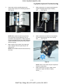
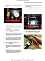
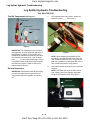
www.mymowerparts.com
Log Splitter Hydraulic Troubleshooting
Log Splitter Hydraulic Troubleshooting
Test Kit # 759-3742
Test Kit Components. See Figure 1.
1.
As a standard service procedure, replace the
hydraulic oil filter._____ See Figure 1.
Flow Meter
Needle Valve
Pressure Gauge
Filter
Figure 1
IMPORTANT: The following test kit information
and systematic questioning allows diagnoses of
the hydraulic log splitter. Proper testing and
maintenance procedures provide safe and effective methods to do these tests. Use the blank
lines “_____” to verify a performed step or record
a test result. Make certain all the test results are
recorded, there will be a need to refer back to
them throughout this test.
General Inspection
IMPORTANT: Always disconnect the spark plug
wire from the spark plug and ground it to the
engine block when the log splitter is not being
run.
Figure 1
NOTE: When installing the hydraulic oil filter,
lubricate the seal with hydraulic fluid, rotate the
filter clockwise by hand until it is snug and complete the installation by rotating the filter 1/8 of a
turn clockwise beyond the snug position.
2.
Check the fluid level and add (or remove) fluid as
required._____
NOTE: Check with the owner to find out what
fluid is being used in the hydraulic log splitter.
DO NOT mix hydraulic fluids. See Figure 2.
Steel Rule
Filler Opening
Figure 2
9 - 14
K&T Saw Shop 606-678-9623 or 606-561-4983
www.mymowerparts.com
Log Splitter Hydraulic Troubleshooting
3.
Inspect the coupler assembly between the
engine and the pump in the following sequence:
See Figure 3.
5.
Make certain there is a square key between the
engine crankshaft and the upper coupling
half._____ See Figure 4.
Set Screw
Coupler
Assembly
Square Key
Figure 4
Figure 3
NOTE: Make certain the spark plug wire has
been removed from the spark plug, and it is
grounded to the engine block. Simply grasp the
coupling assembly by hand and make certain the
engine crankshaft and pump input shaft rotates
with the coupling.
4.
6.
Make certain there is a half-moon key between
the pump input shaft and the lower coupling
half._____ See Figure 5.
Make certain the set screws in the upper and
lower coupling halves are tight using an 1/8”
allen wrench._____
NOTE: Remove and loctite the set screws if they
are loose.
Half Moon Key
Nylon “Spider”
Figure 5
NOTE: Refer to the Flexible Coupler Adjustment
Section for instructions.
7.
Make certain there is a nylon “spider” insert
between the upper and lower coupling
halves._____
9 - 15
K&T Saw Shop 606-678-9623 or 606-561-4983
www.mymowerparts.com
Log Splitter Hydraulic Troubleshooting
8.
12.
Loosen the hose clamp securing the suction
hose to the hydraulic gear pump using a 5/16”
socket or a flat-blade screw driver. See Figure 6.
Start the engine and verify that the engine is
operating between 3500 and 3600 RPM using a
tachometer._____ See Figure 8.
Pump
Clamp
Hose
Figure 8
Figure 6
9.
NOTE: See the engine service manual for correct RPM specifications and procedures.
Momentarily remove the suction hose from the
bottom of the pump and lower it into an oil drain
container, making certain there is sufficient flow
from the reservoir._____ See Figure 7.
13.
Shut the engine off.
Pump Troubleshooting
Pump
1.
Latch the log splitter in the horizontal position._____ See Figure 1.
High
Pressure
Hose
Low Pressure Hose
Latch
Figure 7
10.
Quickly reconnect the suction hose and secure it
in place using a 5/16” socket._____
11.
Check the fluid level and replace the lost
fluid._____
Figure 1
9 - 16
K&T Saw Shop 606-678-9623 or 606-561-4983
www.mymowerparts.com
Log Splitter Hydraulic Troubleshooting
2.
Test Kit Installation Procedures
With the log splitter off, cycle the control valve
forward and rearward several times to relieve
any pressure in the hydraulic system._____ See
Figure 2.
NOTE: The pressure gauge side of the test kit
connects to the pump’s high pressure hydraulic
hose, and the flow gauge side of the test kit connects to the inlet port of the control valve. See
Figure 1.
Male Union to control valve
Control Valve
Female union to high
pressure hose
Figure 2
3.
Male union
Remove the high pressure hydraulic hose from
the inlet port of the control valve using channel
locks and a (1 and 1/8”) wrench._____
Figure 1
Control Valve to Flow Meter Connector
NOTE: Make certain that any dirt or debris is
removed from the hydraulic connections before
they are loosened.
4.
Set the high pressure hydraulic hose into an oil
drain container.
1.
Secure the male union to the inlet side of the
control valve using a 1-1/8” wrench and a large
adjustable wrench to hold the control
valve._____
2.
Secure the male union to the flow meter connector using a 1-1/8” wrench and a 7/8”
wrench._____ See Figure 2.
Control Valve Inlet
Pressure
Gauge
Pressure
Line
Flow Valve
Figure 2
9 - 17
K&T Saw Shop 606-678-9623 or 606-561-4983
www.mymowerparts.com
Log Splitter Hydraulic Troubleshooting
High Pressure Hydraulic Hose to Pressure
Gauge Connector
1.
Secure the male union, female union, and high
pressure hydraulic hose connector to the pressure gauge connector using a 1-1/8” wrench, 11/16” wrench, 7/8” wrench, and a large adjustable wrench._____
2.
Double check all connectors and make certain
they are tight before performing the test procedures._____
valve that is used on the test kit, the GOLD ring
below the needle valve knob will be exposed, or
the number “4” will be showing on the center indicator. See Figure 2.
Test Procedures
IMPORTANT: When instructed to close the needle valve, extreme caution must be exercised.
Leaving the needle valve closed can blow seals
and damage the log splitter. See Figure 1.
Gold Ring
High PSI when running
Figure 2
2.
Start the engine and move the throttle (if
equipped) to fast._____
NOTE: Most log splitters do not have a throttle
control, they are set to run at full throttle at all
times.
Needle Valve Closed
Figure 1
1.
Open the needle valve completely by turning the
knob counter-clockwise._____
NOTE: The needle valve MUST be open before
starting the log splitter. Depending on the needle
9 - 18
K&T Saw Shop 606-678-9623 or 606-561-4983
www.mymowerparts.com
Log Splitter Hydraulic Troubleshooting
3.
Check the engine RPM with a tachometer and
make certain the engine is running between
3500 and 3600 RPM._____ See Figure 3.
6.
Record the pressure of the fluid at the pressure
gauge._____
NOTE: The pressure gauge should read 0 PSI
(pounds-per-square-inch) if the pump is operating correctly.
7.
Slowly close the needle valve clockwise until the
engine begins to labor._____
8.
Continue to close the needle valve slowly until
the high volume check valve closes and the
engine RPM returns to normal._____ See Figure
5.
Figure 3
NOTE: If the engine is not running to specifications, the test results will not be valid. See the
engine service manual to correct the engine
RPM.
4.
The log splitter must be run for a short time to
bring the hydraulic fluid up to 130 degrees Fahrenheit before continuing this test._____
5.
Record the GPM of the fluid flow at the flow
meter._____ See Figure 4.
1-3 GPM
300 -700 PSI
Figure 5
9.
Record the PSI._____
NOTE: The PSI reading should be between 300
and 700 PSI.
10.
8-14 GPM
Record the GPM._____
NOTE: The GPM reading should be between 1
and 3 GPM.
IMPORTANT: If the check valve does not close,
the engine will bog down and stall. (REPLACE
THE PUMP).
11.
0 PSI
Figure 4
If all the recorded data meets the specifications
above, proceed._____
CAUTION: The next test requires the needle
valve to be almost fully closed. It must be
opened immediately after recording the test
results to avoid damage._____
NOTE: The flow meter should read between 8
and 14 GPM (gallons-per-minute) if the pump is
operating correctly.
9 - 19
K&T Saw Shop 606-678-9623 or 606-561-4983
www.mymowerparts.com
Log Splitter Hydraulic Troubleshooting
Final Pump Pressure Test
1.
•
Continue to close the needle valve slowly until
the flow gauge reads approximately 1
GPM._____ See Figure 1.
Scan the Final Pump Pressure Test section and
enter the recorded test result from PSI “A”_____
and GPM “A”_____
Test Procedures
1.
Make certain the needle valve is fully
open._____ See Figure 1.
1500-3200 PSI
1-3 GPM
Figure 1
Needle valve “Open”
NOTE: DO NOT close the needle valve fully.
This is the main pressure hose, and the pump
does not have a relief valve.
2.
Figure 1
Record the PSI._____ This is PSI “A”
NOTE: The PSI “A” should be between 1500 and
3200 PSI.
3.
2.
Start the log splitter._____
3.
Move the control valve handle to the forward
position until the wedge assembly is at the end of
its travel._____ See Figure 2.
Record the GPM._____ This is GPM “A”
NOTE: The GPM “A” should be approximately 1
GPM.
4.
Immediately open the needle valve._____
NOTE: Damage to the pump can be avoided by
opening the needle valve immediately after
recording the test results.
5.
If the PSI reading is below 1500 PSI and the
GPM is above 1 to 2, the pump is defective.
(REPLACE THE PUMP).
6.
Shut the log splitter off.
7.
If all the recorded data meets the specifications
above, perform the following section.
Hold control valve in FORWARD position
Control Valve and Hydraulic Cylinder Troubleshooting
Figure 2
NOTE: This section is to be used after the General Inspection and Pump Troubleshooting sections have been performed._____
4.
Hold the control valve handle in the forward position.
9 - 20
K&T Saw Shop 606-678-9623 or 606-561-4983
www.mymowerparts.com
Log Splitter Hydraulic Troubleshooting
5.
Record the PSI._____ (This is PSI “B”) See Figure 3.
13.
Move the control valve to reverse and retract the
wedge assembly.
14.
Shut the log splitter off and relieve the pressure
in the hydraulic system by cycling the control
valve handle forward to reverse several times.
15.
Remove the test kit from the log splitter using a
7/8” wrench, 1-1/8”, 1-1/16” and a large adjustable wrench.
Low flow, high pressure
Needle valve “Open”, wedge bottomed out
Figure 3
NOTE: The PSI “B” recorded should be equal to
or GREATER than the PSI “A” recorded earlier in
the Pump Troubleshooting section - Final Pump
Pressure Test.
6.
Record the GPM._____ (This is GPM “B”)
7.
Enter the recorded test results from GPM
“A”_____ and GPM “B”_____
8.
If the recorded GPM “B” is equal to or LESS than
the (GPM “A”) recorded earlier in the Pump Troubleshooting section - Final Pump Pressure Test,
the hydraulic fluid flow is correct.
9.
If the recorded GPM “B” is GREATER than the
(GPM “A”) recorded earlier in the Pump Troubleshooting section - Final Pump Pressure Test,
there may be a problem with the control valve,
pressure relief valve, or hydraulic cylinder.
10.
Enter the recorded test results from PSI
“A”_____ and PSI “B”_____
11.
If the (PSI “B”) is equal to or greater than the
recorded (PSI “A”) in the Final Pump Pressure
Test, the hydraulic system is functioning correctly.
12.
Remove Test Kit
Figure 4
16.
Install the high pressure hydraulic hose in the
inlet port of the control valve using a 1-1/16”
wrench and channel locks. See Figure 5.
High pressure line
re-installed
If the (PSI “B”) is less than the recorded (PSI “A”)
in the Final Pump Pressure Test, there may be a
problem with the control valve, pressure relief
valve or hydraulic cylinder. Continue through this
section to determine which part is faulty.
Figure 5
9 - 21
K&T Saw Shop 606-678-9623 or 606-561-4983
www.mymowerparts.com
Log Splitter Hydraulic Troubleshooting
Control Valve, Pressure Relief Valve and
Hydraulic Cylinder Testing
1.
Install the Test Kit in the following
sequence
Make certain the wedge assembly is in the fully
retracted position._____ See Figure 1.
To rear port of
hydraulic cylinder
(Flow side of kit)
To control valve outlet
(Pressure side of kit)
Figure 1
NOTE: The pressure gauge side of the test kit
connects to the control valve, and the flow gauge
side of the test kit connects to the rear port of the
hydraulic cylinder.
Figure 1
2.
3.
Place the log splitter in the vertical position and
lock it in._____
Rear Cylinder Port to Flow Meter Connector.
Remove the steel hydraulic tube that connects
from the rear port of the hydraulic cylinder to the
90 degree fitting on the control valve using two 7/
8” wrenches._____ See Figure 2.
1.
Secure the flow gauge connector directly to the
rear port of the hydraulic cylinder using a 7/8”
wrench._____
Rear of
hydraulic cylinder
90 degree fitting
Steel hydraulic tube
Figure 2
9 - 22
K&T Saw Shop 606-678-9623 or 606-561-4983
www.mymowerparts.com
Log Splitter Hydraulic Troubleshooting
Control Valve 90 Degree Fitting to Pressure Gauge Connector:
1.
Secure the male to female union, male union and
small high pressure hydraulic hose to the pressure gauge connector using a 1-1/8” wrench, 11/16” wrench, 7/8” wrench, and a large adjustable wrench._____
2.
Double check all connectors and make certain
they are tight before performing the test procedures._____
3.
6.
Momentarily close the needle valve completely,
record the PSI gauge and immediately open the
needle valve back up._____ See Figure 1.
Close needle valve slowly,
then open quickly after
taking reading.
Secure the open end of the small high pressure
hydraulic hose to the 90 degree fitting on the
control valve using two 7/8” wrenches.
Test Procedures
IMPORTANT: When instructed to close the needle valve, extreme caution must be exercised.
Leaving the needle valve closed for more than a
few seconds can blow seals and damage the log
splitter.
1.
Scan the above section and enter the recorded
test result from PSI “B”_____
2.
Rotate the needle valve counter-clockwise to the
completely open position._____
3.
Start the engine and move the throttle (if
equipped) to fast._____
Figure 1
CAUTION: This step must be performed very
quickly or damage may occur to the hydraulic
system.
NOTE: Most log splitters do not have a throttle
control, they are set to run at full throttle.
4.
Move the control valve handle to the forward
position until the wedge assembly is at the end of
its travel._____
5.
Hold the control valve handle in the forward position and begin to close the needle valve.
7.
Record the PSI._____ This is (PSI “C”).
8.
Enter the recorded test results from PSI
“B”_____ and PSI “C”_____
9.
If the recorded PSI “C” is equal to the PSI
recorded earlier (PSI “B”), the pressure relief
valve is functioning correctly._____
10.
If the recorded PSI “C” is equal to the PSI
recorded earlier (PSI “B”), but exceeds the 3200
PSI limit, the Pressure Relief Valve Adjustment
section must be performed to lower the
PSI._____
11.
If the recorded PSI “C” is below the PSI recorded
earlier (PSI “B”), the Pressure Relief Valve
Adjustment section must be performed in an
attempt to bring the PSI back into the correct
specifications before condemning the control
valve.
12.
Shut the log splitter off._____
9 - 23
K&T Saw Shop 606-678-9623 or 606-561-4983
www.mymowerparts.com
Log Splitter Hydraulic Troubleshooting
Pressure Relief Valve Adjustment
6.
Depending on the log splitter pressure, turn the
adjustment screw clockwise or counterclockwise
1/8 of a turn using a flat-blade screw driver. See
Figure 2.
Screwdriver
Clockwise
INCREASES
pressure
Pressure relief valve cap
Counterclockwise
DECREASES
pressure
Figure 1
Figure 2
IMPORTANT: This adjustment is extremely sensitive. Slowly turn the adjustment screw one
eighth of a turn at time and recheck the pressure.
1.
Enter the recorded test results from PSI
“B”_____
2.
Rotate the needle valve counter-clockwise to the
completely open position._____
3.
Remove the hex bolt covering the pressure relief
valve using a 5/8” wrench.
4.
Inspect the “O” ring on the hex bolt for damage
or wear._____
5.
Mark the orientation of the adjustment screw on
the outer housing using a flashlight and a sharp
object.
NOTE: Turning the adjustment screw clockwise
increases the pressure. Turning the adjustment
screw counter-clockwise decreases the pressure.
7.
Start the engine and move the throttle (if
equipped) to fast._____
NOTE: Most log splitters do not have a throttle
control, they are set to run fast all the time.
8.
Move the control valve handle to the forward
position until the wedge assembly is at the end of
its travel._____
9 - 24
K&T Saw Shop 606-678-9623 or 606-561-4983
www.mymowerparts.com
Log Splitter Hydraulic Troubleshooting
9.
Hold the control valve handle in the forward position and begin to close the needle valve. See
Figure 3.
17.
Repeat the above section and continue to make
eighth turn adjustments until the correct pressure
relief specifications have been achieved.
NOTE: Always shut the log splitter off when making adjustments.
Close needle valve slowly,
then open quickly after
taking reading.
18.
If the pressure relief valve has been adjusted to
the correct specifications, the control valve is
good. Perform the Hydraulic Cylinder Troubleshooting section.
19.
If the pressure relief valve will not adjust to the
correct specifications, REPLACE THE CONTROL VALVE. See Figure 4.
Figure 3
10.
Momentarily close the needle valve completely,
record the PSI gauge and immediately open the
needle valve back up._____
CAUTION: This step must be performed very
quickly or damage may occur to the hydraulic
system.
11.
Record the PSI._____ The new pressure reading is (and replaces the previous reading) (PSI
“C”).
12.
Enter the recorded test results from PSI
“B”_____ and the new PSI “C”_____
13.
If the recorded PSI “C” is equal to the PSI
recorded earlier (PSI “B”), the pressure relief
valve is functioning correctly, and this is now the
Final PSI “C”._____ Continue to the Hydraulic
Cylinder Troubleshooting section.
14.
If the recorded PSI “C” is equal to the PSI
recorded earlier (PSI “B”), but exceeds the 3200
PSI limit, the Pressure Relief Valve Adjustment
section must be performed to lower the
PSI._____
15.
If the recorded PSI “C” is below the PSI recorded
earlier (PSI “B”), the Pressure Relief Valve
Adjustment section must be performed in an
attempt to bring the PSI back into the correct
specifications before condemning the control
valve.
16.
Shut the log splitter off.
Figure 4
20.
Shut the log splitter off.
Hydraulic Cylinder Troubleshooting.
IMPORTANT: This section is to be performed
after all the other Test Kit sections have been
performed.
1.
Enter the recorded test results from the reading
Final PSI “C”_____.
9 - 25
K&T Saw Shop 606-678-9623 or 606-561-4983
www.mymowerparts.com
Log Splitter Hydraulic Troubleshooting
2.
Rotate the needle valve counter-clockwise to the
completely open position._____ See Figure 5.
NOTE: Seal kits are available from your parts
suppliers. See Figure 6.
Needle valve in
“Open” position
Seals
Cylinder
Piston
Figure 5
3.
Retaining Ring
Figure 6
Start the engine and move the throttle (if
equipped) to fast._____
NOTE: Most log splitters do not have a throttle
control, they are set to run at full throttle.
4.
Move the control valve handle to the forward
position until the wedge assembly is at the end of
its travel._____
5.
Hold the control valve handle in the forward position.
6.
Record the PSI._____ (This is PSI “D”)
7.
Record the GPM._____
8.
Enter the recorded test results from Final PSI
“C”_____ and PSI “D”_____
9.
If the recorded PSI “D” is EQUAL to the PSI
recorded earlier (PSI “C”), and the recorded
GPM is between 0 and 1, the cylinder is good.
10.
If the recorded PSI “D” is LESS than the PSI
recorded earlier Final (PSI “C”), and the recorded
GPM is 2 to 3 or more, the hydraulic cylinder
needs to be repaired.
11.
Replace the hydraulic cylinder ONLY if repairs
are not possible.
12.
Remove the hydraulic log splitter test kit using a
7/8” wrench, 1 - 1/16” wrench, 1 - 1/8” wrench,
and a large adjustable wrench._____
13.
Install the steel hydraulic tube that connects from
the rear port of the hydraulic cylinder to the 90
degree fitting on the control valve using two 7/8”
wrenches._____
9 - 26
K&T Saw Shop 606-678-9623 or 606-561-4983