Download Three-Phase Motors - Franklin Electric
Transcript
Three-Phase Motors
MOTOR APPLICATION
Reduced Voltage Starters
All Franklin three-phase submersible motors are suitable for full-voltage starting. Under
this condition the motor speed goes from zero to full speed within a half second or less.
The motor current goes from zero to locked rotor amps, then drops to running amps
at full speed. This may dim lights, cause momentary voltage dips to other electrical
equipment, and shock power distribution transformers.
In some cases the power companies may require reduced-voltage starters to limit this
voltage dip. There are also times when reduced-voltage starters may be desirable
to reduce motor starting torque thus reducing the stress on shafts, couplings, and
discharge piping. Reduced-voltage starters also slow the rapid acceleration of the water
on start-up to help control upthrust and water hammer.
Reduced-voltage starters may not be required if the maximum recommended cable
length is used. With maximum recommended cable length there is a 5% voltage drop
in the cable at running amps, resulting in about 20% reduction in starting current and
about 36% reduction in starting torque compared to having rated voltage at the motor.
This may be enough reduction in starting current so that reduced-voltage starters are
not required.
Three-Lead Motors: Autotransformer or solid-state reduced-voltage starters may be
used for soft-starting standard three-phase motors.
Six-Lead Motors: Wye-Delta starters are used with six-lead Wye-Delta motors. All
Franklin 6" and 8" three-phase motors are available in six-lead Wye-Delta construction.
Consult the factory for details and availability. Part winding starters are not compatible
with Franklin Electric submersible motors and should not be used.
Wye-Delta starters of the open-transition type, which momentarily interrupt power
during the starting cycle, are not recommended. Closed-transition starters have no
interruption of power during the start cycle and can be used with satisfactory results.
Reduced-voltage starters have adjustable settings for acceleration ramp time,
typically preset at 30 seconds. They must be adjusted so the motor is at full voltage
within THREE SECONDS MAXIMUM to prevent excessive radial and thrust bearing wear.
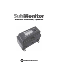
If Subtrol-Plus or SubMonitor is used the acceleration time must be set to TWO
SECONDS MAXIMUM due to the 3 second reaction time of the Subtrol-Plus or
SubMonitor.
Solid-state starters AKA soft starts may not be compatible with Subtrol-Plus/
SubMonitor. However, in some cases a bypass contactor has been used. Consult the
factory for details.
During shutdown, Franklin Electric’s recommendation is for the power to be removed,
allowing the pump/motor to coast down. Stopping the motor by ramping down the
voltage is possible, but should be limited to three (3) seconds maximum.
When autotransformer starters are used, the motor should be supplied with at least
55% of rated voltage to ensure adequate starting torque. Most autotransformer starters
have 65% and 80% taps. Setting the taps on these starters depends on the percentage
of the maximum allowable cable length used in the system. If the cable length is less
than 50% of the maximum allowable, either the 65% or the 80% taps may be used.
When the cable length is more than 50% of allowable, the 80% tap should be used.
Inline Booster Pump Systems
Franklin Electric offers three different types of motors for non-vertical applications.
1.
2.
The Booster motors are specifically designed for booster applications. They are
the “Best Choice” for sealed Reverse Osmosis applications. These motors are
the result of two years of focused development and bring additional value and
durability to booster module systems. These motors are only available to OEMs or
Distributors who have demonstrated capability in Booster Module systems design
and operation and adhere to Franklin’s Application Manual requirements.
The Hi-Temp motors have many of the internal design features of the Booster
motor. It’s additional length allows for higher temperature handling and the Sand
Fighter sealing system provides greater abrasion resistance. One or both of these
conditions are often experienced in open atmosphere applications such as lakes,
ponds, etc.
3.
The Standard Vertical Water Well (40-125 hp) motors can be adapted to nonvertical applications when applied per the below guidelines. However, they will
be more sensitive to application variances than the other two designs.
All of the above motors must be applied per the guidelines listed below. In addition,
for all applications where the motor is applied in a sealed system, a Submersible
Motor Booster Installation Record (Form 3655) or its equivalent must be completed at
start-up and received by Franklin Electric within 60 days. A sealed system is one where
the motor and pump intake are mounted in a sleeve and the water feeding the pump
intake is not open to the atmosphere.
Continued on next page
36
Three-Phase Motors
MOTOR APPLICATION
Inline Booster Pump Systems (Continued)
Design And Operational Requirements
2. Motor, Sleeve, and Pump Support System: The booster sleeve ID must be sized
according to the motor cooling and pump NPSHR requirements. The support system
must support the motor’s weight, prevent motor rotation, and keep the motor and
pump aligned. The support system must also allow for thermal axial expansion of
the motor without creating binding forces.
3. Motor Support Points: A minimum of two support points are required on the
motor. One in the motor/pump flange connection area and one in the bottom end
of the motor area. The motor castings, not the shell area, are recommended as
support points. If the support is a full length support and/or has bands in the shell
area, they must not restrict heat transfer or deform the shell.
4. Motor Support Material and Design: The support system shall not create any areas
of cavitation or other areas of reduced flow less than the minimum rate required
by this manual. They should also be designed to minimize turbulence and vibration
and provide stable alignment. The support materials and locations must not inhibit
the heat transfer away from the motor.
5. Motor and Pump Alignment: The maximum allowable misalignment between the
motor, pump, and pump discharge is 0.025 inch per 12 inches of length (2 mm per
1000 mm of length). This must be measured in both directions along the assembly
using the motor/pump flange connection as the starting point. The booster sleeve
and support system must be rigid enough to maintain this alignment during
assembly, shipping, operation, and maintenance.
6. Lubrication and Heat Resistance: The best motor lubrication and heat resistance
is obtained with the factory based propylene glycol fill solution. Only when an
application MUST HAVE deionized (DI) water should the factory fill solution be
replaced. When a deionized water fill is required, the motor must be derated as
indicated on the below chart. The exchange of the motor fill solution to DI water
must be done by an approved Franklin service shop or representative using a
vacuum fill system per Franklin’s Motor Service Manual instruction. The motor shell
then must be permanently stamped with a DI closely behind the Serial Number.
The maximum pressure that can be applied to the motor internal components
during the removal of the factory fill solution is 7 psi (0.5 bar.)
1.8
1.75
1.7
Pump Load Multiplier
1. Non-Vertical Operation: Vertical Shaft-up (0°) to Horizontal (90°) operation is
acceptable as long as the pump transmits “down-thrust” to the motor within
3 seconds after start-up and continuously during operation. However, it is best
practice to provide a positive slope whenever it is possible, even if it is only a
few degrees.
Derating Factor for Motors That Must Have Their Factory Fill
Replaced With Deionized Water 8" Encapsulated Motor
1.65
1.6
1.55
1.5
1.45
1.4
1.35
1.3
1.25
1.2
1.15
1.1
1.05
1
1.00 Service Factor
1.15 Service Factor
40
35
(50Hz)
(60Hz)
30
25
20
15
10
Feed Water Temperature (°C)
FIG. 9
First:
Determine maximum Feed Water Temperature that will be experienced in this
application. If the feed water exceeds the maximum ambient of the motor, both
the DI water derating and a hot water application derating must be applied.
Second:
Determine the Pump Load Multiplier from the appropriate Service Factor curve.
(Typical 1.15 Service Factor is for 60 Hz ratings & 1.00 Service Factor for
50 Hz ratings).
Third:
Multiply the Pump Load Requirement times the pump load multiplier number
indicated on the vertical axis to determine the Minimum Motor Nameplate Rating.
Fourth:
Select a motor with a nameplate equal or higher than the above calculated value.
7. Motor Alterations - Sand Slinger & Check Valve Plug: On 6" and 8" motors, the
rubber sand slinger located on the shaft must be removed. If a pipe plug is
covering the check valve, it must be removed. The special Booster motor
already has these modifications.
8. Frequency of Starts: Fewer than 10 starts per 24-hour period are recommended.
Allow at least 20 minutes between shutdown and start-up of the motor.
9. Controls-Soft Starters and VFDs: Reduced voltage starters and variable speed
drives (inverter drives) may be used with Franklin three-phase submersible
motors to reduce starting current, upthrust, and mechanical stress during start-up.
The guidelines for their use with submersible motors are different than with
normal air cooled motor applications. Refer to the Franklin Electric Application,
Installation, and Maintenance (AIM) manual Reduced Voltage Starters section or
Variable Speed Submersible Pump Operation, Inverter Drives sections for specific
details including required filtering.
Continued on next page
37
Three-Phase Motors
MOTOR APPLICATION
Inline Booster Pump Systems (Continued)
Motor Overload Protection: Submersible motors require properly sized ambient
compensated Class 10 quick-trip overloads per Franklin’s AIM manual guidelines
to protect the motor. Class 20 or higher overloads are NOT acceptable. Franklin’s
SubMonitor is strongly recommended for all large submersibles since it is
capable of sensing motor heat without any additional wiring to the motor.
Applications using Soft Starters with a SubMonitor require a start-up bypass consult the factory for details. SubMonitor can not be used in applications using
a VFD control.
10.
Motor Surge Protection: Properly sized, grounded, and dedicated motor surge
arrestors must be installed in the supply line of the booster module as close
to the motor as possible. This is required on all systems including those using
soft-starters and variable speed drives (inverter drives).
11.
Wiring: Franklin’s lead assemblies are only sized for submerged operation
in water to the motor nameplate maximum ambient temperature and may
overheat and cause failure or serious injury if operated in air. Any wiring
not submerged must meet applicable national and local wiring codes and
Franklin Cable Chart Tables 16-21. (Notice: wire size, wire rating, and insulation
temperature rating must be known when determining its suitability to
operate in air or conduit. Typically, for a given size and rating, as the
insulation temperature rating increases its ability to operate in air or conduit
also increases.)
12.
14.
Pressure Relief Valves: A pressure relief valve is required and must be selected to
ensure that, as the pump approaches shut-off, it never reaches the point that the
motor will not have adequate cooling flow past it.
15.
System Purge (Can Flooding): An air bleeder valve must be installed on the
booster sleeve so that flooding may be accomplished prior to booster start-up.
Once flooding is complete, the booster should be started and brought up to
operating pressure as quickly as possible to minimize the duration of an upthrust
condition. At no time should air be allowed to gather in the booster sleeve
because this will prevent proper cooling of the motor and permanently
damage it.
16.
System Flush – Must Not Spin Pump: Applications may utilize a low flow
flushing operation. Flow through the booster sleeve must not spin the pump
impellers and the motor shaft. If spinning takes place, the bearing system will be
permanently damaged and the motor life shortened. Consult the booster pump
manufacturer for maximum flow rate through the pump when the motor is
not energized.
17.
Open Atmosphere Booster Pump Systems: When an open booster is placed
in a lake, tank, etc. that is open to atmospheric pressure, the water level must
provide sufficient head pressure to allow the pump to operate above its NPSHR
requirement at all times and all seasons. Adequate inlet pressure must be
provided prior to booster start-up.
Check Valves: Spring-loaded check valves must be used on start-up to minimize
motor upthrusting, water hammer, or in multiple booster (parallel) applications
to prevent reverse flow.
13.
Table 38 Franklin Cable Chart (See item 12 Wiring above)
CABLE
TEMP.
RATING
(°C)
75
90
125
#10 AWG
#8 AWG
#6 AWG
#4 AWG
#2 AWG
MOTOR
NAMEPLATE RATED
AMPS FULL LOAD
IN AIR
IN
CONDUIT
IN AIR
IN
CONDUIT
IN AIR
IN
CONDUIT
IN AIR
IN
CONDUIT
IN AIR
IN
CONDUIT
3-LEAD (DOL)
6-LEAD (Y-∆)
3-LEAD (DOL)
6-LEAD (Y-∆)
3-LEAD (DOL)
6-LEAD (Y-∆)
40A
69A
44A
76A
66A
114A
28A
48A
32A
55A
46A
80A
56A
97A
64A
111A
77A
133A
40A
69A
44A
76A
53A
91A
76A
132A
84A
145A
109A
188A
52A
90A
60A
104A
75A
130A
100A
173A
112A
194A
153A
265A
68A
118A
76A
132A
105A
181A
136A
236A
152A
263A
195A
337A
92A
159A
104A
180A
134A
232A
Based on 30 °C maximum ambient with cable length of 100 feet or less.
Continued on next page
38
Three-Phase Motors
MOTOR APPLICATION
Inline Booster Pump Systems (Continued)
Four Continuous Monitoring System Requirements for Sealed
Booster Systems.
1.
2.
39
Water Temperature: Feed water on each booster must be continuously
monitored and not allowed to exceed the motor nameplate maximum
ambient temperature at any time. IF THE INLET TEMPERATURE EXCEEDS THE
MOTOR NAMEPLATE MAXIMUM AMBIENT TEMPERATURE, THE SYSTEM MUST
SHUTDOWN IMMEDIATELY TO PREVENT PERMANENT MOTOR DAMAGE. If feed water
temperatures are expected to be above the allowable temperature, the motor
must be derated. See Franklin’s AIM manual Hot Water Applications section for
derating guidelines. (The high temperature feed water derating is in addition
to the exchange to DI water derating if the motor factory fill solution was
exchanged to DI water.)
Inlet Pressure: The inlet pressure on each booster module must be continuously
monitored. It must always be positive and higher than the NPSHR (Net Positive
Suction Head Requirement) of the pump. A minimum of 20 PSIG (1.38 Bar) is
required at all times, except for 10 seconds or less when the motor is starting and
the system is coming up to pressure. Even during these 10 seconds the pressure
must remain positive and be higher than the NPSHR (Net Positive Suction Head
Requirement) of the pump.
PSIG is the actual value displayed on a pressure gauge in the system piping. PSIG
is the pressure above the atmospheric conditions. If at any time these pressure
requirements are not being met, the motor must be de-energized immediately
to prevent permanent damage to the motor. Once the motor is damaged, it is
usually not immediately noticeable, but progresses and results in a premature
motor failure weeks or months after the damage occurred.
Motors that will be exposed to pressure in excess of 500 psi (34.47 Bar) must
undergo special high pressure testing. Consult factory for details
and availability.
3.
Discharge Flow: The flow rate for each pump must not be allowed to drop below
the motor minimum cooling flow requirement. IF THE MOTOR MINIMUM COOLING
FLOW REQUIREMENT IS NOT BEING MET FOR MORE THAN 10 SECONDS, THE SYSTEM
MUST BE SHUT DOWN IMMEDIATELY TO PREVENT PERMANENT MOTOR DAMAGE.
4.
Discharge Pressure: The discharge pressure must be monitored to ensure that
a downthrust load toward the motor is present within 3 seconds after start-up
and continuously during operation. IF THE MOTOR DISCHARGE PRESSURE IS
NOT ADEQUATE TO MEET THIS REQUIREMENT, THE SYSTEM MUST BE SHUT DOWN
IMMEDIATELY TO PREVENT PERMANENT MOTOR DAMAGE.


