1
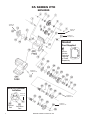
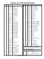
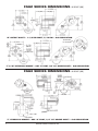
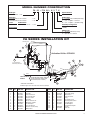
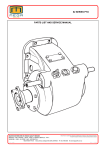
FA SERIES
FORD AUTOMATIC PTO
PARTS LIST AND SERVICE MANUAL
Muncie Power Products, Inc.
FA SERIES PTO
EXPLODED
Torque To
18 Ft. Lb.
Torque To
5 Ft. Lb.
Torque To
18-25 Ft. Lb.
Gasket
Ford Supplied
44
Reuse
Gasket
Found on
Opening
or Order
Separately
Torque To
18-25 Ft. Lb.
Bearing Removal
Location
Torque To
16 Ft. Lb.
Exhaust
Port
2
Torque To
18-25 Ft. Lb.
Torque To
18-25 Ft. Lb.
Activation
Port
MUNCIE POWER PRODUCTS, INC.
PARTS LIST AND DESCRIPTION
ITEM
ITEM
QTY
PART NO.
DESCRIPTION
22
1
1
49T36288
49T37342
Piston Cup (FA62 Only)
Piston Cup (FA64 Only)
23
1
1
12T36863
12T36540
Piston O-ring (FA62 Only)
Piston O-ring (FA64 Only)
24
1
1
7
8
6
1
1
1
2
1
1
49T36287
49T37341
49T36259
27T36286
49T36258
21T37085
02T36254
10T37008
21T29017
10T37009
24T35480
Piston (FA62 Only)
Piston (FA64 Only)
Friction Disc
Wave Spring
Spacer Disc
Thrust Washer
Output Bell Gear
Bearing
Thrust Washer
Thrust Bearing
Snap Ring
34
1
1
1
1
1
06T36295
06T36253
06T38823
06T39154
06T37325
Output Shaft “B” (FA62 Only)
Output Shaft “T” (FA62 Only)
Output Shaft “Q” (FA62 Only)
Output Shaft “R” (FA64 Only)
Output Shaft “T” (FA64 Only)
35
1
1
36
1
1
26T01627
25T37387
25T35724
25T35520
10T21017
10T37229
Woodruff Key “B” (FA62 Only)
Cap Plug “T” (Both)
Cap Plug “Q” (FA62 Only)
Cap Plug “R” (FA64 Only)
Bearing (FA62 Only)
Sealed Bearing (FA64 Only)
37
38
39
40
41
42
43
44
45
N.S.
1
1
4
3
1
1
2
1
1
1
12T36751
See Table A
19T39257
19T32740
25T21684
25T37702
25T34029
13T37386
19T37726
43TK3890
Cover O-ring (FA62 Only)
Flange/Seal Kit
Capscrew
Capscrew
Pipe Plug
Cap Plug
Cap Plug
Ford Transmission Gasket
Storage Capscrew (FA64 Only)
Lube Kit
QTY
PART NO.
DESCRIPTION
1
2
1
03T36247
10T36244
18T36282
1
18T36281
1
18T36257
1
18T36256
1
18T36255
Input Gear
Input Bearing
Input Bearing Spacer
(.110/.106")(Blue)
Input Bearing Spacer
(.116/.112")(Beige)
Input Bearing Spacer
(.122/.118")(Red)
Input Bearing Spacer
(.128/.124")(Alum.)
Input Bearing Spacer
(.134/.130")(White)
4
2
12T37037
O-ring
5
1
07T36243
Input Idler Shaft
6
1
19T36249
Set Screw
7
1
08T37194
Idler Shaft
25
26
27
28
29
30
31
32
33
8*
2
10T40073
Tapered Roller Bearing
9*
1
18T37245
1
18T37246
1
18T37247
1
18T37248
1
18T37249
1
18T37250
1
18T37251
1
18T37252
1
18T37253
10*
1
04T37190
Idler Bearing Spacer
(.2526/.2496")(White)
Idler Bearing Spacer
(.2476/.2446")(Yellow)
Idler Bearing Spacer
(.2426/.2396”)(Pink)
Idler Bearing Spacer
(.2376/.2346")(Orange)
Idler Bearing Spacer
(.2326/.2296")(Green)
Idler Bearing Spacer
(.2276/.2246")(Brown)
Idler Bearing Spacer
(.2226/.2196")(Red)
Idler Bearing Spacer
(.2176/.2146")(Blue)
Idler Bearing Spacer
(.2126/.2096")(Black)
Reverse Idler Gear
11
1
12T37701
O-ring
12
1
12T37203
O-ring
13
1
22T37322
Flange Nut
1
2
3*
14
15
16
17
18
19
21
1
15T36568
Cover (FA62 Only)
1
15T37289
Cover (FA64 Only)
1
1
1
2
1
1
1
1
2
2
12T36280
12T36279
12T37278
10T21017
10T37320
01T37306
01T37238
24T23937
24T37625
12T36877
12T37321
N.S.
O-ring
Cover O-ring (FA62 Only)
Cover O-ring (FA64 Only)
Bearing (FA62 Only)
Bearing (FA64 Only)
Housing (FA62 Only)
Housing (FA64 Only)
Snap Ring (FA62 Only)
Snap Ring (FA64 Only)
O-ring (FA62 Only)
O-ring (FA64 Only)
1
20TK4070
Stud Kit (FA62 Only)
1
20TK4071
Stud Kit (FA64 Only)
N.S.
1
52TK3963
Instruction Packet
N.S.
1
13T37626
N.S.
1
49TK4557
H.E.G.O. Sensor Gasket
(FA64 Gas Engine Only)
Pump Seal Kit (FA64 Only)
* Reverse Idler Gear, Idler Bearing, and Shim are sold as an
assembly only. The Shim color code listed is a paint mark which
is found on the edge of the Spacer.
TABLE A - Flange/Seal Kit (Item 38)
14TA5160
“B” Flange/Seal Kit (Includes 15T34576 Bearing Cap &
14TA3997
“Q”, “R”, & “T” Flange/Seal Kit
14T37781
“W” Hydraulic Flange
11T37790 Oil Seal)
(Includes 14T39141
Hydraulic Flange & 11T37790 Oil Seal)
MUNCIE POWER PRODUCTS, INC.
(Requires 11T37790 Oil Seal)
3
IN INCHES (MM) FA62
SERIES DIMENSIONS
IN INCHES (MM)
“B” OUTPUT SHAFT • 1-1/4 RD SHAFT, 5/16 KW • 4x2 APPLICATION
ORIENTATION
“W” HYD OPTION
“T”or “W” HYDRAULIC MOUNT • SAE “A” PILOT, 3/4" 11T SPLINE SHAFT • 4x2 APPLICATION
IN INCHES (MM) FA64
SERIES DIMENSIONS
IN INCHES (MM)
“T” HYDRAULIC MOUNT • SAE “A” PILOT, 3/4" 11T SPLINE SHAFT • 4x4 APPLICATION
4
MUNCIE POWER PRODUCTS, INC.
MODEL NUMBER CONSTRUCTION
FA 62 – F14 06 – H 3 T X
PTO Type
Special Feature
Ford Automatic — FA
X — None
Mounting
Output Type
SAE 6 Bolt Mount 4x2 Chassis
SAE 6 Bolt Mount 4x4 Chassis
— 62
— 64
Trans.
FA Gear Data
Ford
14.2P 15.9°PA 18° LH
B — 1-1/4 Round 5/16 KW (FA62 Only)
T — 3/4 - 11 Spline - 2 Bolt “A”
W — 3/4 - 11 Spline - (Tandem Pump)
Assembly Arrangement
— F14
2 (FA64)
3 (FA62)
Speed Ratio
06 — .62:1
Shifter Type
H — Electric/Hydraulic (12 Volt)
Z — Special 2 Pos Switch
FA SERIES INSTALLATION KIT
WEATHER-PACK
ORANGE
BLACK
4
18
METRI-PACK
5
27
26
12
6
TO TRANSMISSION
MAIN PRESSURE PORT
12
26
Activation Kit No. 43TK4521
11
26
IN
9
BLACK
GREEN
11
8
24
10
21
*
2 25
BLUE
GREEN
BLACK
FORD VEHICLE
WIRING
1
20
4-WIRE
CONNECTOR
14
23
Circuit #640 (Red w/Yellow) or
Circuit #295 (Blue w/Pink) 1999-2001
Circuit #294 (White w/Blue) 2002
Circuit #322 (Blue w/Yellow)
22
## Green light to turn "ON" when PTO switch is activated.
QTY
PART NO.
DESCRIPTION
1
2
3
4
5
6
8
9
10
11
12
14
1
1
1
1
1
1
2
1
1
2
2
1
36MA1005
36T36271
30T37620
35T37928
30T37954
43T36231
43T68014
44MB0222
43T37503
45T36274
45M4R528
43T37385
Switch Bracket
Face Plate
Rocker Switch 12v
12v Solenoid Valve
Pressure Switch
Tee Fitting
Elbow, 1/8 JIC To JIC
Male Elbow 1/8 NPT
1/8 JIC Adapter
Hose Assembly 28"
Pressure Hose Assembly
Orifice Elbow
##
RED
* GROUND TO BATTERY
ITEM
3
BLACK
ITEM
QTY
PART NO.
DESCRIPTION
18
19
20
21
22
23
24
25
26
N.S.
N.S.
N.S.
1
1
1
1
1
3
1
1
5
1
1
6
31T37602
32T37370
34T37601
37T35674
37T37621
19T37518
36T37517
36T37516
43T36431
Temperature Sensor
Temperature Gauge
Wire Harness
Rubber Grommet
Relay
Sheet Metal Screw
Mounting Bracket, Dash
Face Plate, Dash
1/8 ODT Adapter
Solenoid Mounting Kit
Bolt Kit
Cable Ties
MUNCIE POWER PRODUCTS, INC.
36MK1007
28T35442
5
TWO POSITION ONLY ROCKER SWITCH INSTALLATION
(SHIFT CODE OPTION “Z”)
1. The 2 position switch option does not
change the way the harness or the rocker
switch are installed. Refer to Steps 27
thru 41 of the FA Series PTO Owner’s
Manual (IN97-05) for the basic instructions. In this “Z” option the relay (PN
37T37621) is not used, and the socket
remains on the harness unused.
2. When installing “Z” option the rocker
switch note that the wire harness connector has a green wire, which should be positioned at the top; this will line up with the green light on the rocker switch (PN 30T37752).
3. Installation does not require any modification to the existing wiring harness.
PTO INSTALLATION
WITH FORD
SUPPLIED APCM
(DEALER OPTION ONLY)
Optional 36MK1210-A Light Kit
1. Muncie harness PN 34T38267.
2. Connect the new harness as shown in the
figure.
3. The standard rocker switch is not used,
install a PTO indicator light in clear view
of operator while seated in driver’s seat.
Order 36MK1210-A separately.
PTO INSTALLATION WITH SPD-1001A SPEED SWITCH
Orange Green
1. Make the PTO installation as described in
Blue
White
Steps 1-41 of the FA Series
Ground
PTO Owner’s Manual (IN97-05).
Ground
Black
Black
Red
2. Find the 4-wire connector on the Muncie
Engine
SPD-1001A
PTO Harness and plug in the wire harness
Compartment
adapter 34T37753. The adapter is designed
Grommet
Blue
Ground
to assemble only in one direction.
Overspeed Light
Diagram "A"
To Battery
3. Find the Red wire on this adapter harness
which goes to the 4-wire connector and
connect this wire to the SPD harness Red
Red
Ford 294
wire as shown in Diagram “A”.
White/Blue
Ford 322
OR
Blue/Yellow
4. Connect the SPD Blue wire to the Green
Ford 295
Black
Blue/Pink
wire on the adapter harness as shown in
OR
Ford 294
Diagram “A”.
Red/Yellow
5. The Ford supplied alternator should have a
three wire connector plugged into it with a
Light Green w/Red, an Orange w/Light
Blue, and a White w/Black Stripe. The
To Transmission
White w/Black is the wire to splice into for Main Pressure Port
the Orange SPD wire. For 2002 model year,
there is a clean tachometer output circuit
located with body builder pass-through
wires at left of steering column. Circuit
#76, Light Green w/White trace, connect
Diagram A
Blue Wire
this to the Orange SPD wire.
Red Wire SPD-1001A
6. Connect the Black SPD wire to a good ground at the fuse panel or battery (not to the cab).
Green Wire
Red Wire
FA PTO
7. Connect the White wire to the Overspeed light provided. Ground the other terminal of the Light.
4 Wire Connector
4 Wire Connector Wiring Harness
8. Mount the SPD after making the calibration setting as described in the SPD installation manual
34T37753
To FA PTO
To Rocker Switch
Harness Adapter
(IN07-04).
X
Relay
IN
6
MUNCIE POWER PRODUCTS, INC.
FA SERIES DISASSEMBLY AND REASSEMBLY
(REFERENCE EXPLODED VIEW & PARTS LIST ON PAGES 2 & 3)
DISASSEMBLY PROCEDURE
INPUT GEAR
1. Remove set screw #6.
2. Drive idler shaft #5 from PTO.
3. Remove input gear #1 and bearings #2 and shim #3.
INTERMEDIATE GEAR
1. Remove the Input gear set first.
2. Remove hex nut #13 from idler shaft #7. Note position of slot on shaft.
3. Using brass hammer or soft drift drive the idler shaft #7 from the
housing #18. Be careful not to damage shaft end.
4. Remove the idler gear #10 and bearings #8 from unit.
OUTPUT GEAR
1. On the FA62 remove the output bearing cover #39.
2. Remove the 3 cap screws #41 from closed bearing cover #14.
3. Using brass hammer or soft drift drive output shaft #34 from housing
#18 in the direction of clutch pack. Closed bearing cover #14 will go
with the shaft.
4. Remove the output bearing #36 if it stays in the housing #18 when
you drive the shaft #34 out.
5. Remove the pipe plug #43 from the end cover #14. Remove plastic
plug #45 or any fittings in cover.
6. Using a punch with a small enough end to fit through the holes in flat
of bearing cover #14. Drive the bearing #17 from the cover.
7. Using a bearing puller remove the bearings #17 & #36 (if Req.) from
both ends of the output shaft #34.
8. Remove snap ring #19 from piston end #22 & #24 of shaft by pushing in on piston cup #22 and using a snap ring tool to remove ring #19.
9. Slide piston #24 and piston cup #22 from the end of shaft #34.
10. Remove the fiction disks #25, spacer disks #27 and wave springs
#26 from the shaft #34.
11. Remove snap ring #33 from gear side of bell gear #29 and remove
gear #29, roller bearing #30, thrust washers #31 and thrust bearing #32.
12. Remove O-rings #4, #11, #12, & #15 from within housing #18.
13. Remove the O-rings #21 from the output shaft #34.
REASSEMBLY PROCEDURE
Lubricate O-rings prior to installation
1. Place the bell gear #29 thrust washer #28 on to output shaft #34.
2. Place bell gear roller bearing #30 on to shaft #34.
3. Place bell gear #29 over the roller bearing #30 and slide against the
thrust washer #28.
4. Place thrust washer #31 on to shaft and against bell gear #29.
5. Place thrust bearing #32 against thrust washer #31.
6. Place 2nd thrust washer #31 against thrust bearing #32.
7. Install snap ring #33 on output shaft #34 to hold thrust bearing #32
and bell gear #29 in place.
8. Install clutch plates into bell gear #29 by placing wave spring #26 on
first, then a friction disk #25, then a spacer plate #27 and continuing
until you have placed eight wave springs, seven friction disks, and six
spacer disks in bell gear. Finish with a wave spring.
9. Install O-rings #21 on to the output shaft #34.
10. Install piston O-ring #23 onto piston #24 and push piston #24 all the
way into piston cup #22. Piston #24 has a hub on it and it should be
facing out as piston is installed into piston cup #22.
11. Push the piston/piston cup assembly onto the output shaft #34.
12. Push down on piston cup assembly while installing #19 snap ring.
13. Install O-ring #15 and #16 into bearing cover #14.
14. Install Ball bearing #17 into rear cover #14.
15. Install output shaft assembly into bearing cover #14 by taping bearing onto shaft evenly.
16. Install output shaft assembly into housing #18. Install output bearing
#36 (FA64 must use sealed bearing) into housing and onto output
shaft #34.
17. Install the 3 bearing cover cap screws #41.
18. Install output bearing cover #39 on FA62 series w/4 cap screws #40.
19. Install pipe plug #43 into bearing cover. It doesn’t matter which pipe port.
INSTALLING INTERMEDIATE SHAFT
Lubricate O-rings prior to installation.
Idler Gear is sold as an assembly only, and includes shim
and bearings with pre-load established from the factory.
1. Proper shimming of the tapered roller bearings are critical. Be sure to
purchase gear and bearing as an assembly from factory.
2. Place tapered roller bearings #8 into intermediate gear #10 with
spacer #9 and place this setup into housing #18.
3. Place O-rings #11 & #12 into intermediate gear location of housing
and grease.
4. When installing idler shaft #7 make sure the groove for clearance to
input gear is positioned towards aperture opening. Draw a line perpendicular to middle of slot. This line should point to center of input
idler shaft.
5. Insert intermediate idler shaft #7 through the large hole in side of
housing into gear and bearing set and press into place. Do not use
nut to pull idler shaft into place.
6. Using lock nut #13, tighten on idler shaft #7 and torque to 18-25 Ft.Lb.
INPUT GEAR ASS’Y
Lubricate O-rings prior
to installation
1. Install input shaft ass’y Orings #4. Place input bearings #2 into input gear #1.
2. Place input gear #1 into
housing #18 so that gear
clears internal interference
on idler shaft #7 as
described earlier in
step 6 above.
3. Note location of set screw hole in
housing and align hole in idler
shaft as shaft is installed. Press
idler shaft #5 from set screw side
of housing #18 and install shaft
#5 through the two input bearings #2. Then drive shaft in the
opposite direction approximately 1" until shaft #5 is just
below #2 bearing surface.
Using one of the shims #3
find largest shim that will
push in between bearing and
housing without having to
hit it into place. This should
give a clearance between
shim #3 and housing #18
of .002" to .006" loose.
4. When proper pre-load is
established, continue installing
idler shaft #5 until set screw #6
hole lines up.
5. Install set screw #6.
MUNCIE POWER PRODUCTS, INC.
7
FA SERIES STUD KITS
FA64 Series
FA62 Series
STUD KIT
STUD KIT
20TK4071
20TK4070
ITEM QTY PART NO.
1
2
3
4
2
2
19T37727
20T37914
22T39282
ITEM QTY PART NO.
DESCRIPTION
12 pt. Metric Capscrew 25mm
Alignment Stud
Hex Nut
FA SERIES SOLENOID VALVE
1
2
3
4
5
6
N.S.
FA Series PTO Solenoid
requires diode protection
by vehicle manufacturer.
Included in this kit is a
Jumper Connector which
contains a diode. Install
this into the Wire
Connector prior to connecting to the PTO
Activation Wiring Harness.
1
3
2
1
1
2
1
DESCRIPTION
20M39045
22T39282
19T37727
20T37224
22T37605
20T37914
13T37626
10mm Stud
Hex Nut
12 pt. Metric Capscrew 30mm
Step Stud
Lock Nut
Alignment Stud
Hego (O2) Sensor Gasket
VAVLE ASSEMBLY
FOR ALL FA SERIES
ITEM QTY PART NO. DESCRIPTION
34T39811
DIODE
CONNECTOR
FA64 PUMP SEAL KIT - 49TA4557
1
1
35T37928
2
1
35T36092
3
4
5
N.S.
1
1
1
1
Valve Assembly, Manifold
Valve Cartridge Assembly
(Inc. Item 3 , 4 , 5 & Seals)
22T36498 Retaining Nut
37T36496 12V Coil
35T37997 Valve Stem
12TK3902 Seal Kit
FA64 SERIES PTO PUMP MODIFICATION INSTRUCTIONS
This kit is used to convert the FA64 series PTO coupled to a Muncie
PF2 Series pump to a “Wet Spline” configuration.
The enclosed parts include an o-ring that goes on the pump pilot, and
a brass ball that is to be driven into the weep hole of the pump flange.
Perform this modification with the pump removed from the PTO:
1. Check the pump weep hole for a brass ball already inserted into
hole (photo 2). If it is there, then discard ball provided.
2. The brass ball is slightly larger than the hole and will deform during the installation, effectively sealing the hole.
Install this ball into the hole as shown (photos 1 and 2). A small
hammer is required.
3. Place the o-ring around the pump pilot as shown in photo 3.
1
4 - 5 ft.lb.
4
2
B
3*
A
20 ft.lb.
PS
photo 1
photo 2
photo 3
Muncie Power Products, Inc. Member of the Interpump Hydraulics Group
General Offices and Distribution Center • P.O. Box 548 • Muncie, IN 47308-0548
(765) 284-7721 • FAX (765) 284-6991 • E-mail [email protected]
Web site http://www.munciepower.com
SP97-03 (Rev. 4-10) Printed in the U.S.A.
© Muncie Power Products, Inc. 2010
Drive Products, Exclusive Agents for Canada, ISO Certified by an Accredited Registrar
CL
4