1
CS6, CS8, CB6 & CB8 SERIES
CLUTCH SHIFT PTO
PARTS LIST AND SERVICE MANUAL
Muncie Power Products, Inc.
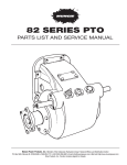
CS6 & CS8 SERIES
EXPLODED VIEW
Cover Detail
See Page 7
input gear assembly
See Page 4
Clutch pack
disk locations
output shaft
See Page 6
MUNCIE POWER PRODUCTS, INC.
PARTS LIST AND DESCRIPTION
item qtypart no.description
item qtypart no.description
1
2
2a
3
4
4a
5
6
7
8
8a
9
10
10a
11
12
13
14
15
16
17
18
18a
19
20
20b
21
22
23
24
25
26
27
28
29
30
31
32
1
2
2
1
4
1
2
4
1
1
1
1
1
1
1
4
1
1
1
1
2
2
1
1
1
1
1
8
7
2
1
1
2
2
1
1
1
2
1
1
1
10T34006
10T35776
18T34622
21T34621
10T34620
19T35237
15T36717
15T36860
15T39966
11T36124
24T36894
12T34003
10T21017
10T21017
10T38248
26T36175
21T36473
21T36511
21T36512
24T27240
24T35480
21T29017
10T36285
10T37008
02T38792
24T37951
49T33564
49T33563
27T38791
49T36560
49T38878
49T38387
49T38758
12T36054
12T36472
12T36471
12T36053
49T36561
49T36464
49T36115
49T38757
24T36470
24T36040
12T35949
12T35774 19T35785
07T35947
07T37071
01T36713
01T36706
01T37073
01T37072
01T37107
01T37106
01T37966
01T37965
01T39816
01T39817
01T38337
01T38338
See Gear Data Chart Page 5 (Table A)
Input Bearing (03-04) – (A6705)
Input Bearing (05-14)
Spacer (03-04) – (A6705)
Thrust Race (03-04)
See Chart Page 5 (Table B)
Thrust Bearing (03-04) – (A6705)
Capscrew
Closed Cover Std.
Closed Cover (CS6G)
Closed Cover CB Series (see page 8)
Seal
Snap Ring
O-Ring
Bearing
Bearing (std.)
Bearing (I, D or Z)
Roll Pin (not included CS_G or CB_)
Plate (not included CS_G or CB_)
Thrust Washer (not included CS_G or CB_)
Plate (not included CS_G or CB_)
Snap Ring
Snap Ring
Thrust Race
Bearing
Bearing (2 or 4 Assy - requires 18 & 18a) (see pg.4)
See Output Gear Chart Page 5 (Table C)
Clutch Hub
Snap Ring (I, D or Z)
Friction Disc
Spacer Disc
Spring
Piston (CS8)
Piston (CS6)
Piston (I, D or Z)
Piston (2 & 4 Assy)
O-Ring (CS8)
O-Ring (CS6)
O-Ring
O-Ring (I, D or Z)
Piston Cup — (CS8 ) (5.25” O.D.)
Piston Cup — (CS6 ) (4.5” O.D.)
Piston Cup (I, D or Z) (5.25” O.D.)
Piston Cup (2 & 4 Assy) (5.25” O.D.)
Snap Ring
Snap Ring (I, D or Z)
O-Ring (03-04) + (A6705)
O-Ring (05-14)
Setscrew
Idler Shaft (03-04) + (A6705)
Idler Shaft (05-14)
6 Bolt Housing (03-04) ‘1’ STD & (A6705)
6 Bolt Housing (03-04) ‘3’ STD & (A6705)
6 Bolt Housing (05-14) ‘1’, ‘2’ STD
6 Bolt Housing (05-14) ‘3’, ‘4’ STD
6 Bolt “N” Housing (05-14) ‘1’ “N”
6 Bolt “N” Housing (05-14) ‘3’ “N”
6 Bolt “F” Housing (05-14) ‘1’ ‘F’ F84
6 Bolt “F” Housing (05-14) ‘3’ ‘F’ F84
6 Bolt Housing (03-04) ‘1’ (I, D or Z)
6 Bolt Housing (03-04) ‘3’ (I, D or Z)
6 Bolt Housing (05-14) ‘3’ (I, D or Z)
6 Bolt Housing (05-14) ‘1’ (I, D or Z)
33
34
35
36
37
38
41
42
48
49
50
1
1
1
1
1
4
1
4
1
1
1
2
2
1
1
1
2
01T39411
01T36715
01T36711
01T37075
01T37074
01T38350
01T38351
01T38856
01T38857
16T41119
19T41118
13M13541
13M35091
13M35092
13M35151
13M35152
13T35198
13T35199
43T37385
26T37992
6 Bolt Housing Special (39409)
8 Bolt Housing (03-04) ‘1’ STD
8 Bolt Housing (03-04) ‘3’ STD
8 Bolt Housing (05-14) ‘1’, ‘2’ STD
8 Bolt Housing (05-14) ‘3’, ‘4’ STD
8 Bolt Housing (05-14) ‘3’ (I, D or Z)
8 Bolt Housing (05-14) ‘1’ (I, D or Z)
8 Bolt Housing (05-14) ‘3’ (E)
8 Bolt Housing (05-14) ‘1’ (E)
Output Shaft See Page 6
Woodruff Key See Page 6
O Ring See Page 6
Seal See Page 6
Output Flange See Page 6
Capscrew See Page 6
Cover
Capscrew
Allison Gasket .031 (U60)
Gasket .010 6-Bolt
Gasket .020 6-Bolt
Gasket .010 8-Bolt
Gasket .020 8-Bolt
Gasket .010 (I85)
Gasket .020 (I85)
Orifice Fitting (P - Special Option)
Dowel Pin (F84 Only)
GASKET/SEAL KITS AND REBUILD KITS See Page 13
NOTE: A68 input is replaced by A67 input options.
MUNCIE POWER PRODUCTS, INC.
2
5
CS6 & CS8 SERIES
INPUT GEAR ASSEMBLIES
4
4
4
5
5
2
4
1
1
3
2
3
4
4
2
2a
4
4
2
1
2a
5
5
4a
Ratios 03,04
Ratio A6705 (after 6/07)
1 or 3 Arrng.
2a
2a
2a
1
1
1
2a
2a
4a
Ratios 05, 06, 07, 09, 12, 14
Ratio A6805 (before 6/07)
1 or 3 Arrng.
2a
4a
Ratios 05, 06, 07, 09, 2 or 4 Arrng
4
ITEM QTY PART NO.
DESCRIPTION
1
2a
2
2a
3
4
4a
Input Gear – Page 5
Input Bearing (03 & 04)+(A6705)
Input Bearing (05 - 14)
Spacer (03 & 04)+(A6705)
Thrust Race (03 & 04)+(A6705)
1 Bearing Shims – Page 5
Input
1
2
2
1
4
1
1
See TABLE A
2a
10T34006
10T35776
18T34622
21T34621
SEE TABLE B
2a
4a
2a
MUNCIE POWER PRODUCTS, INC.
4a
4a
GEAR DATA
TABLE A — INPUT GEAR - ITEM 1
Desig. Part No. Teeth Gear Data
A6703 A6704 A6705 **A6805 *A6907 C6112 C7009 C7012 F1012 F1107 F6107 F6307 F6309 F6312 F6607 F6609 F6612 F7005 F7007 F7009 F8405 F8407 F8409 F8412 F8507 F8607 F8609 I8403 I8404 I8405 I8407 I8505 I8507 M6504 M6505 03T41318 03T41319 03T41320 03T40699 03T37980 03T37067 03T37652 03T37068 03T37984 03T37156 03T37147 03T37086 03T38356 03T37087 03T38502 03T38503 03T38504 03T38195 03T38194 03T40234 03T37741 03T37742 03T37743 03T37908 03T37066
03T39447 03T39448 03T37329 03T37330 03T37331 03T37332 03T37091 03T37092 03T36775 03T37070 26/14 26/17 26/18 26/18 30/23 20/30 23/26 23/30 42/30 42/23 21/23 24/23 24/26 24/30 24/23 24/26 24/30 26/18 26/23 26/26 28/18 28/23 28/26 28/30 34/23 28/23 28/26 34/14 34/17 34/18 34/23 38/18 38/23 26/17 26/18 6.86P 20º PA SPUR
6.86P 20º PA SPUR
6.86P 20º PA SPUR
6.86P 20º PA SPUR ≠
6.86P 20º PA SPUR
6.1P 25º PA 32.28º LH
7P 25º PA 30.78º LH
7P 25º PA 30.78º LH
10.1P 20º PA SPUR
10.1P 21.5º PA SPUR
6.1P 20.5º PA 29 LH
6.35P 20º PA 22º LH
6.35P 20º PA 22º LH
6.35P 20º PA 22º LH
6.65P 20º PA 21.5º LH
6.65P 20º PA 21.5º LH
6.65P 20º PA 21.5º LH
7P 23º PA 26 LH
7P 23º PA 26 LH
7P 23º PA 26 LH
8.38P 18º PA 33.1 LH
8.38P 18º PA 33.1 LH
8.38P 18º PA 33.1 LH
8.38P 18º PA 33.1 LH
8.55P 21º PA SPUR
8.38P 18º PA 33.1 RH
8.38P 18º PA 33.1 RH
8.46P 20º PA SPUR
8.46P 20º PA SPUR
8.46P 20º PA SPUR
8.46P 20º PA SPUR
8.46P 20º PA SPUR
8.46P 20º PA SPUR
6.48P 17.65º PA SPUR
6.48P 17.65º PA SPUR
Desig.
Part No.
M6507
M6509
M6512
M8306
M8307
M8309
S6007
S6807
S6809
S6812
S6814(8-Bt)
S7009
S7107
S7109
S7307
S7309
S7312
U6003
U6004
U6005
U6806
U6807
U6809
U6812
U6814(8-Bt)
U6005
U6809
03T37058
03T37059
03T37060
03T38760
03T38761
03T38762
03T37061
03T37062
03T37063
03T37064
03T37110
03T37065
03T37149
03T37134
03T37919
03T38171
03T38170
03T36737
03T36738
03T37069
03T38262
03T37038
03T37039
03T37040
03T37042
03T38803
03T38801
TeethGear Data
26/23
26/26
26/30
30/20
30/23
30/26
21/23
26/23
26/26
26/30
26/33
24/26
29/23
29/26
28/23
28/26
28/30
24/14
24/17
24/18
24/20
24/23
24/26
24/30
24/33
24/18
24/26
6.48P 17.65º PA Spur
6.48P 17.65º PA Spur
6.48P 17.65º PA Spur
8.38P 19.16ºPA 24 º 58’ LH (2&4 Assy)
8.38P 19.16ºPA 24 º 58’ LH (2&4 Assy)
8.38P 19.16ºPA 24 º 58’ LH (2&4 Assy)
6P 17.5º PA 26.17º LH
6/8P 20º PA Spur
6/8P 20º PA Spur
6/8P 20º PA Spur
6/8P 20º PA Spur
7P 17.5º PA 28.07º LH
7P 17.5º PA 18º LH
7P 17.5º PA 18º LH
7P 22.5º PA 19º LH
7P 22.5º PA 19º LH
7P 22.5º PA 19º LH
6P 20º PA Spur
6P 20º PA Spur
6P 20º PA Spur
6/8P 20º PA Spur
6/8P 20º PA Spur
6/8P 20º PA Spur
6/8P 20º PA Spur
6/8P 20º PA Spur
6P 20º PA Spur(2&4 Assy)
6/8P 20º PA Spur(2&4 Assy) **Produced after 06/07 uses needle bearings and requires the 03-04 housing. A67 input gear replaces A68 input gear.
* Requires 23M60270 and 20TK4360 to mount.
≠ Requires housing change to 03-04 housing on units date before 06/07.
TABLE B — INPUT GEAR BEARING SHIMS - ITEM 4a (Shim Kit 18TK4586) (1 of ea.)
Item 4a Dimension
Item 4a Dimension
Item 4a Dimension
18T35783 18T38725 18T35782 18T38726 18T35781 Shim 0.1150 / 0.1130
Shim 0.1175 / 0.1155
Shim 0.1200 / 0.1180
Shim 0.1225 / 0.1205
Shim 0.1250 / 0.1230
18T38727 18T36230 18T38728 18T36229 18T38729 Shim 0.1275 / 0.1255
Shim 0.1300 / 0.1280
Shim 0.1325 / 0.1305
Shim 0.1350 / 0.1330
Shim 0.1375 / 0.1355
18T37151 18T38730 18T37152 18T38731 18T37153 Shim 0.1400 / 0.1380
Shim 0.1425 / 0.1405
Shim 0.1450 / 0.1430
Shim 0.1475 / 0.1455
Shim 0.1500 / 0.1480
TABLE C — OUTPUT GEAR - ITEM 19
Part No. Ratio
Teeth
Part No. Ratio
Teeth
Part No. Ratio
Teeth
02T36744
02T36745
02T36746
02T37913
02T36747
02T36748
02T36749
42T
39T
38T
36T
33T
30T
26T
02T36750
02T38988
02T38989
02T38990
02T38991
02T38817
02T38992
23T
42T I&Z Output
39T I&Z Output
38T I&Z Output
36T I&Z Output
33T I&Z Output
30T I&Z Output
02T38994
02T38995
02T38763
02T38764
02T38765
02T38766
02T41324
02T41325
02T41326
26T I&Z Output
23T I&Z Output
38T 2&4 Ass’y
36T 2&4 Ass’y
33T 2&4 Ass’y
30T 2&4 Ass’y
42T (A67)
39T (A67)
38T (A67)
03
04
05
06
07
09
12
14
03
04
05
06
07
09
MUNCIE POWER PRODUCTS, INC.
12
14
05
06
07
09
03
04
05
18
Ratios 05,06,07,09 (2 or 4 Arrng.)
18a
19
CS6 & CS8
SERIES
OUTPUT GEAR 2 OR174 ASSEMBLIES
18
PART NO.
DESCRIPTION
17
18
18a
19
21T29017
10T36285
10T37008
See TABLE C
Thrust Race
Bearing
Bearing (2 or 4 Assy requires 18 & 18a)
Output Gear – Page 5
Ratios 05, 06, 07, 09 (2 or 4 Arrng.)
OUTPUT SHAFT & FLANGE
33
40
10a
33
35
40
36
37
33
37
38
10a
35
36
33 37
39
40b
19
17
ITEM QTY
2
1
1
1
18a
47
Typical Hydraulic Flange
“X” Shaft
40
10a
39
35
37
36
47 37
37d
“C” & “2” Companion Flange
37c
39
ITEM QTY PART NO.
DESCRIPTION
10a
33
34
35
36
Bearing (std.)
37
1
15T34576
Bearing Cover, Open “B”, “2”, “C”, “X”***
Bearing (“I”, “D” or “Z”)
14T37779
Hyd Flange “K” “P”
Output Shaft “B” 1-1/4” Rd
14T39137
Hyd Flange “G”
Output Shaft “G” Dana Special
14T38354
Hyd Flange “I”
Output Shaft “D” DIN 5462
14T39406
Hyd Flange “I” (CS6G), “D” (std. end cover)
(with special mounting hole)
14T39141
Hyd Flange “Q” “R” & “T”
Output Shaft “K” 7/8”-13 Spl
14T35464
Hyd Flange “S”
Output Shaft “Q”&”S” 7/8”-13 Spl
14T38343
Hyd Flange “Z”
Output Shaft “P” “L” 1”-15 Spl
14T37378
“2” Companion Flange
Output Shaft “R” 5/8”-9 Spl
14T37357
“C” Companion Flange
Output Shaft “T” 3/4-11 Spl
14T38981
Hyd Flange (“6”)
Output Shaft “2”, “C”, “X” 20 Spl
14T40714
Flange “L”– (for Low Box – pg. 15)
Typ. Hyd. Flange
Output Shaft “B” (CS6G)
14T38719
Hyd Flange (E)
Output Shaft “K”&”6” (CS6G)
37c
1
19M38266
Capscrew (“2”, “C”, “X”)
Output Shaft “I” CS6G DIN 5462
37d
1
21T20092
Flat Washer (“2”, “C”, “X”)
Output Shaft “I” Std. DIN 5462
38
4
19T33233
Capscrew (“B”)
(same as “D” without special hole)
39
4
19T34462
Socket Capscrew “K” “P”& “Z” “L” Hyd
Output Shaft “Z” 1-1/4”-14 Spl
19T39257
Socket Capscrew “G” “Q” “S” “R” “T” Hyd
Output Shaft “B” 2 or 4 Assy
19M84478
Socket Capscrew “I” “D”
Output Shaft “K” 2 or 4 Assy
19T96512
Socket Capscrew “I” CS6G
Output Shaft “P” 2 or 4 Assy
39
8
19M84478
Capscrew (E) 8 Req.
Output Shaft “E” Special Order 1-1/4”-14 Spl
40
1
28T36546
Spacer, Hyd Output
Woodruff Key
40b
1
24T38347
Snap Ring I, Z, D
O Ring
47
1
25T35724
Cap Plug “K” “S” “Q” “G” (Storage Only)
O Ring (“I” “D” & “Z”)
25T35725
Cap Plug “P” (Storage Only)
Seal
*** It is recommended to use Loctite #640 on outside of seal when replacing seal in this Seal (“E” “I” “D” & “Z”)
1
1
1
1
1
1
10T21017
10T38248
06T36892
06T37088
06T41013
06T36893
06T37090
06T37089
06T38964
06T37336
06T37372
06T37167
06T37168
06T39526
06T38996
06T38908
06T38767
06T39533
06T40236
06T40205
26T01627
12T36751
12T38344
11T37790
11T37795
Typ. Hyd. Flange
Typ. Hyd. Flange
ITEM QTY PART NO.
DESCRIPTION
47
"X" Shaft
"C" & "2" Comp. Flange
bearing cover.
MUNCIE POWER PRODUCTS, INC.
CS6, CS8 SERIES
ITEM #7 END COVER DETAIL
46
CS6S, 6B, 6N, CS8S, 8B
45
46
45
46
45
ITEM QTY
PART NO.
DESCRIPTION
44
45
46
25T21684
19T36174
27T36173
Pipe Plug
Setscrew
Spring
2
4
4
46
45
44
44
46
46
45
45
46
46
45
45
CB6/8 COVER
DETAIL ON PG. 8
44
44
CS6G, CS8G
ITEM QTY
PART NO.
DESCRIPTION
44
25T21684
Pipe Plug
2
ASSEMBLYASSEMBLY
OF 2 or 4 ARRANGEMENT
CS6/8 CS6/8
OF 2 or 4 ARRANGEMENT
ASSEMBLY OF 2 OR 4 ARRANGEMENT CS6/8
19
18
19
18a
18
24 18a
24
33
18
18
27
27
33
Components for the 2 & 4 arrangement
are listed on pages 3,4 ,5 &6.
4a
4a
1
2 or 4 Arrangement
7 2 or 4 Arrangement
1
4a
4a Note the additional bearing in the 2/4
arrangement PTO.
1 or 3 ArrangementNote the location of the input gear shim
1 or 3 Arrangement
4a on each assembly.
7
MUNCIE POWER PRODUCTS, INC.
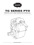
CB6 & CB8 SERIES
EXPLODED VIEW
1
2
1
3
2
4
3
4
5
5
6
7
6
8
7
8
9
9
10
10
11
11
12
12
13
13
CB6, CB8 SERIES PTO
WITH HI-TORQUE BRAKE
itemqty.
Part no.
Description
15T39966
28T39965
24T24315
49T33563
49T33564
28T39964
12T35343
12T39967
28T39963
27T40389
28T40390
24T35480
06T39874
06T40812
25T21684
Cover
Brake Ring
Snap Ring
Spacer Disc
Friction Disc
Brake Hub
O-Ring
O-Ring
Piston
Spring
Spacer
Snapring
1-1/4 Rd. Shaft
“K” Hyd. Shaft
Pipe Plug
1
2
3
4
5
6
7
8
9
10
11
12
13
14
1
1
1
add 4
add 3
1
2
1
1
1
1
1
1
2
14
Cover
Detail
(Backside)
14
Cover
Detail
(Backside)
These components replace the drag brake components, Items 11,12,13,14,15 and items 7 & 33 found on
page 2 & 3. The clutch plates and discs are additional to the ones shown on page 2 & 3.
End cover (item 1) shown here uses the seal and snap ring (items 8 and 8a) shown on pages 2 & 3 and are
not shown here.
The CB series is only available with the standard round output shaft, 1-1/4 round with key and the Hydraulic
SAE B 7/8” 13T spline, and only arrangements 1 or 3.
The CB series brake does not need to be adjusted.
MUNCIE POWER PRODUCTS, INC.
CS6 & CS8 SERIES
CS6S DISASSEMBLY AND REASSEMBLY
DISASSEMBLY PROCEDURE
(REFERENCE EXPLODED VIEW ON PAGE 2)
- DENOTES SPECIAL SERVICE PROCEDURES
1. Remove the CS6S input gear, by removing the set screw in the pad and
driving the idler shaft from the housing. (Items 30,32)
2. Remove the set screws (Item 45) from the bearing cover (Item 7) which hold
7
10
16
14
the drag brake springs (Item 46). Position the housing so that the springs fall
from housing.
3. Remove the four (4) capscrews (Item 6) which hold the back cover to the PTO
housing.
4. Position the housing against a bench block and hit the end of the output shaft
with a soft face hammer to remove the entire output shaft assembly with
6
wbearing cover.
5. Remove the two (2) pipe plugs (Item 44) from the bearing cover. This exposes the ball bearing assembly within the cover.
6. Using a 1/4” punch and alternating between the two holes, drive the bear7
ing and shaft assembly from the bearing cover.
12
7. Using a bearing puller remove the rear bearing (Item 10) by grabbing the
drag brake plate (Item 12) and removing both pieces. The bronze brake disk
(Item 13) can be removed.
8. Using a bearing puller remove the drag brake rotor (Item 14) . 9. The piston and clutch pack may be serviced without removal of the drag brake. Using snap ring pliers, remove the snap ring
(Item 28) located on the output shaft end while gently pushing on the piston cup (Item 27).
10. Pull the piston cup (Item 27) from the shaft and the piston (Item 24) will go with it.
11. Tap the piston cup on a wood surface to remove the piston.
12. Remove the spring (Item 23). The clutch friction discs (Item 21) and spacer discs (Item 22) and inner clutch hub (Item 20) can
be removed by pointing the shaft end down.
13. With the drag brake removed, the snap rings (Item 15 & 16) on this end
of the bell gear can be removed with snap ring pliers. This allows the
bell gear to be removed towards the closed end. The internal bearing
(Item 18) of the bell gear can easily be removed.
REASSEMBLY PROCEDURE
16
14. The reassembly of the unit is made in reverse of the disassembly.
15. Be sure to lubricate the o’rings and all bearings upon installation. Torque capscrews to the values shown or to the following values. • 1/4 set screw - 9 ft. lb. • 5/16 capscrews - 18 ft. lb. • 5/16 Hyd. Flange CS - 25 ft.lbs. • 3/8 capscrews - 36 ft. lb.
16. Place the input bearing into the input gear and slide this group into the
housing to line up the idler shaft.
17. Tap the idler shaft into the housing and through both bearing races. 18. To seat the bearings, tap the idler shaft in the reverse direction while
rotating the gear back and forth. Move the shaft so that it is flush with
the bearing in this assembly. Position the PTO so that the idler shaft is
pointed down and perpendicular to the table. Insert the thickest shim
that can be installed by hand in the gap between the bearing and the housing. Rotate the input gear to ensure it is not excessively tight or loose. Using a feeler
gauge, measure the clearance between the shim and the bearing race. Recommended bearing clearance is .002” loose to .006” loose. If measurement is less than
.002” then remove the shim and replace it with the next thinner shim. If the measurement is greater than .006” then remove the shim and replace with the next thicker shim.
17. Be sure to place the thrust washer and thrust bearing on each side of the input gear prior to
inserting gear assembly into housing.
18. This does not require measuring the preload of the bearings. Be sure to align the washers
and bearings in the idler shaft as the shaft is inserted into the housing.
19. Tap the idler shaft into position and install the set screw.
DRAG BRAKE ADJUSTMENT (the GB series brake does not need to be
adjusted)
19
SPACER
Needle Roller bearing Installation:
DRAG BRAKE
ADJUSTMENT
SET SCREW
13
17
18
Tapered Roller bearing Installation:
33
19
NEEDLE
BEARING
THRUST
WASHER
BEARING
WASHER
(BOTH SIDES OF GEAR)
DRAG BRAKE
ADJUSTMENT
SET SCREW
20. When installing the rear cover be sure to align the roll pins in the drag brake plate with
the holes in the rear cover. 21. After the cover has been attached to the housing insert the springs into the holes.
22. Insert the setscrew over the spring and turn the screw seven (7) full turns.
23. Follow the test and adjustment procedures in the PTO Owner’s manual.
MUNCIE POWER PRODUCTS, INC.
CLUTCHSHIFT SERIES
ELECTRIC/AIR SHIFT
ITEM QTY PART NO.
INSTALLATION KIT 48TK3928
OPTIONAL
CONNECT TO THE EOS or SPD
INPUT SIGNAL CONNECTION
Connect Directly to Air Tank
Do Not Use Hose or Tubing
Connect Directly to Air Tank
Do Not Use Hose or Tubing
18
20
18
20
9
9
8
8
11
11
11
15
See Page 14
CONNECT TO THE EOS or SPD
INPUT SIGNAL CONNECTION
11
20
11
12
6
17
6
17
CUT
HERE
FOR
SPD
CUT
INST.
HERE
FOR
SPD
INST.
To Lube Tap
Required On Automatic
ToTransmissions
Lube Tap
Required On Automatic
Transmissions
21
23
20
12
11
19
19
15
OPTIONAL
22
23
22
#
#
21
13
13
7
2
7
10
14
10
15
OPTIONAL
SPD-1000A
OVERSPEED
OPTIONAL
CONTROL
SPD-1000A
OVERSPEED
CONTROL
2
**
1
**
4 ##
15
CTO
Tach.
CTO
Output
Tach.
Output
1
14
4 ##
16
5
16
5
Battery Ground
Solenoid to be mounted in engine compartment out of direct spray of road contaminents.
RED light to turn “ON” when PTO switch is activated.
CLUTCHSHIFT SERIES
ELECTRIC/HYDRAULIC SHIFT
Description
30T36270
Switch Assembly 12V (Incl 1,2,4)
1
1
36MA1005 Switch Bracket
2 1
36T36271 Face Plate W/O Light Access
4
1
30T35687
Rocker Switch 12v
5
1
33T36299
Fuse Assembly
6
1
35M30692 12v Solenoid Valve
7
1
30T37954 Pressure Switch
8 1
31M15759 Press. Protection Valve
Page 14 Pipe Nipple
9 1 See
44MB2164
10
1
34T36941
See Page 14 Wiring Pigtail
11
2
44MB6844 Male Connector
12
2
44MB6842 Male Connector
13
1
25T21684 Pipe Plug (Use As Req.)
14
3
34M18250 Female Spade Connector
15
2
34M18009 Ring Terminal
16
12 37M18000 Electric Wire 12ft.
17
1
31M14732 Press. Safety Switch (N.O. 80 PSI)
18
1
44MB2254 Street Tee
19
1
44MB0942 Reducer Bushing
20
1
45M44430 Air Tubing 30ft
23
1
44MB2252 StreetTee
N.S. 1
48TA3953 Solenoid Bracket Kit
Additional Parts Included with “P” SPECIAL FEATURE
21
1
45M4R536 Lube Hose Ass’y
22
1
43T37385
Orifice Fitting
NS
1
43M05522 Elbow (F85 Only)
NS
2 43T37429
Fitting (I85 ONLY) For 24V Electric/Air Kit No. 48TK3931, Substitute:
30T36453 Switch Ass’y 24v (Incl 1,2,4)
4
1
30T35712
Rocker Switch 24v
6
1
35M31692 Solenoid Valve 24v
For connection to SPD1001A use 36TK4971 (12v) (sold separately)
** 1
32MSR12V Light Assembly
1
36M01006 Face Plate W/ Light Access
2
34M18187 Spade Terminal
ITEM QTY PART NO.
Description
30T36270
Switch Assembly 12V (Incl 1,2,4)
1
1
36MA1005 Switch Bracket
2 1
36T36271 Face Plate W/O Light Access
INSTALLATION KIT 48TK3927B
4
1
30T35687
Rocker Switch 12v
5
1
33T36299
Fuse Assembly
On automatic transmissions with externally,
OPTIONAL
solenoid controlled converter neutral lock-up, in 6
1
35M12340B 12v Solenoid Valve
stall the ClutchShift activation circuit completely
OPTIONAL
CONNECT TO THE EOS or SPD
7
1
30T37954 Pressure Switch
separate of the lock-up circuit. Do Not use the
INPUT SIGNAL
same valve to operate both circuits.
CONNECT
TO THECONNECTION
EOS or SPD
9 1
34T36941
Wiring Pigtail
TO TRANSMISSION
INPUT SIGNAL CONNECTION
See Page Female
14 Spade Connector
MAIN PRESSURE PORT
13
3
34M18250
TO TRANSMISSION
See
Page
14
MAIN PRESSURE PORT
See Page 14
14
2
34M18009 Ring Terminal
**
15 12 37M18000 Electric Wire 12ft.
**
CYL **
IN
To Lube Tap
16
1
43T35867 Elbow, Pipe To JIC
** ** 19
1
2
CYL
IN
To
Lube
Tap
Required
On
Automatic
17
3
**
1
2
19
1
44MB2252 Street Tee
#
Required
On Automatic
Transmissions
19
17
3
# 6
Transmissions
EXH
NS
1
19T36623
Capscrew
18
6
EXH
18
16
NS
1
22T35140
Hex Nut
*
**
16
*
NS ** 1
21T37991
Lock Washer
**
**
14
Additional ##
Parts Included with “P” SPECIAL FEATURE
14
17 ##1
45M4R536 Lube Hose Ass’y
CUT
HERE
CUT
FOR
18
1
43T37385
Orifice Fitting
HERE
2
SPD
7
FOR
INST.
2
NS ## ##1
43M05522 Elbow (F85 ONLY)
SPD
7
1
INST.
13
1
9
2
43T37429 Fitting (I85 ONLY) 13
** NS
9
**
For 24V Electric/Hydraulic Kit No. 48TK3930B, Substitute:
30T36453 Switch Ass’y 24v (Incl 1,2,4)
* 1414
4
*
4
1
30T35712
Rocker Switch 24v
OPTIONAL
4 ##
##
SPD-1000A
OPTIONAL
CTO
6
1
35M24340B Solenoid Valve 24v
15
SPD-1000A
OVERSPEED
CTO
15
Tach.
OVERSPEED
CONTROL
*
For connection to SPD1001A use 36TK4971 (12v) (sold separately)
Tach.
5
CONTROL
*
Output
5
Output
** 1
32MSR12V Light Assembly
1
36M01006 Face Plate W/ Light Access
2
34M18187 Spade Terminal
Battery Ground
Not Supplied with Standard Installation Kit. Order Muncie 131-2-0001 Separately.
Solenoid to be mounted in engine compartment out of direct spray of road contaminents.
RED light to turn “ON” when PTO switch is activated.
10
MUNCIE POWER PRODUCTS, INC.
CLUTCHSHIFT SERIES
MANUAL AIR SHIFT
ITEM QTY PART NO.
INSTALLATION KIT 48TK4508 - 12V LIGHT
Connect Directly to Air Tank
Do Not Use Hose or Tubing
To Lube Tap
Required On Automatic
Transmissions
9
3
15
15
16
18
6
5
10
8
9
17
11
4
14
7
1
13
##
12
Battery Ground
RED light to turn “ON” when PTO switch is activated.
## RED light to turn "ON" when PTO switch is activated.
* Battery Ground
Description
1
1 32M12001 Light Assembly 12v
2
1
33T36299 Fuse Assembly 3
1 35M18653 Air Valve 4
1 30T37954 Pressure Switch 5
1 31M15759 Press. Protection Valve
6
1 44MB2164 Pipe Nipple 7
1
34T36941 Wiring Pigtail 8
1
44MB6942 Fitting - Elbow 9
2
44MB6842 Male Connector 10 1
44MB6844 Male Connector 11 1
25T21684 Pipe Plug 12 2 34M18009 Ring Terminal
13 12 37M18000 Electric Wire 12ft.
14 3 34T36362 Closed End Crimp 15 1 45M44430 Air Tubing 30ft
18 1 44MB2252 Street Tee
N.S. 1
36MA1004 Dash Bracket
N.S.
1
36T38978 Face Plate
N.S.
1
36MK1007 Bolt Kit
Additional Parts Included with “P” SPECIAL FEATURE
16 1 45M4R536 Lube Hose Ass’y 17 1 43T37385 Orifice Fitting For 24V Electric/Air Kit No. 48TK4509 , Substitute:
1
1 32M24001 Light Ass’y 24v
2
ACC TAP
CS 6S - M65 07 - E 1 B X
PTO Type
Clutch Shift (Standard Drag Brake) CS
Clutch Brake (Optional Shaft Brake) CB
Special Feature
X - None
C - Pulse Gen./Pres Lube/SPD1001A
D - Pulse Gen/SPD1001A
P - Pressure Lube
R - Pulse Gen/No Press Lube
S - Pulse Gen/Pressure lube
Mounting
SAE 6 Bolt Std Mtg -6S
SAE 6 Bolt Non-Std. Mtg. -6D
SAE 6 Bolt Non Std Mtg Deep -6N
SAE 6 Bolt Std Mtg Metric -6M
SAE 6-Bolt Non Std Metric -6C
SAE 8 Bolt Std Mtg. -8S
SAE 8 bolt Std Metric -8M
SAE 8 Bolt Non Std Mtg -8D
SAE 8 Bolt Non Std Mtg Metric -8C
Output Type
B - 1-1/4 Round 5/16 KW
C - 1410 Comp Flg
D - DIN 5462 (Euro)
G - Special
I - DIN 5462
K - SAE B 2&4 Bolt
P - SAE B-B 2&4 Bolt
Q - SAE A 2 Bolt R - SAE A 2 Bolt
S - SAE B 2 Bolt
T - SAE A 2 Bolt
Z - SAE B 2&4 Bolt C shaft
2 - DIN Comp Flg
6 - SAE B 2 Bolt
Transmission (Input Gear Options)
Aisin
-I84
Fuller
-F84
Aisin
-I85
Fuller
-F85
Allison
-A67
Fuller
-F86
Allison
-A69
Mack
-M65
Clark/Fuller -C61
Mercedes -M83
Clark/Fuller -C70
Spicer
-S73
Fuller
-F10
Spicer
-S71
Fuller
-F11
Spicer -S60
Fuller
-F61
Spicer
-S70
Fuller
-F63
Universal -S68
Fuller
-F66
Universal -U60
Fuller
-F70
Universal -U68
Assembly Arrangement
1, 2, 3, or 4 See Below
Shifter Type
A — Manual Air
H — Electric/Hyd 12v
E — Electric/Air 12v J — Electric/Hyd 11
24v
F — Electric/Air 24v 5/16
Speed Ratio*
03 -- 0.33:1 07 -- 0.70:1
04 -- 0.44:1 09 -- 0.87:1
05 -- 0.47:1 12 -- 1.15:1
06 -- 0.56:1 14 -- 1.44:1 (8Bolt Only)
ARRANGEMENT
*Not all combinations are available for input gear options. Refer to application catalog or service parts list.
1
2
MUNCIE POWER PRODUCTS, INC.
3
4
11
DIMENSIONS
3.00
[76.2]
4.00
[101.6]
4.58
116.3]
7.28 [184.9]
.31 [7.9] WOODRUFF KEY
4.13
[104.9]
CL PORT
2.75
[69.9]
1.13 [28.7]
CL
3.08
[78.2]
ÿ1.25 [31.8]
3.33
[84.6]
3.33 [84.5]
0.50 [12.7]*
1.17*
[29.7]
3.50
[88.9]
1.25
[31.8]
0.895
[22.7]
2.44
[62.0]
3.12
[79.2]
6.25 [158.8]
0.84 [21.2]
CS6S / 8S Housing Dimension
4.62*
[117.3]
4.88 [123.9]
7.00 [177.8]
9.25 [235.0]*
Standard 1 1/4 Round Keyed Shaft ("B" Option)
SAE “A” 2 Bolt
Special 7/8-13 Spline — “G” Option
Optional Pump Bolt
Kit 19MK4717 - Sold
Separately
5/16-18UNC-2B 4PLS.
5.42 [137.7]
7/8" [22.2] 13T INV.
SPLINE SHAFT
0.81[20.6]
0.25[6.35]
1/2-13UNC-2B 4PLS.
EQ. SP. ON 5.00[127.0] DIA B.C.
3.25[82.6]
DIA.
0.42[10.7]
SAE “B” 2 Bolt 7/8-13 Spline — “S” Option
1/2-13UNC-2B 2PLS.
EQ. SP. ON 5.75[146.1] DIA B.C.
5.80[147.3]
7/8" [22.2] 13T INV.
SPLINE SHAFT
1.20[30.5]
POSITION HOLE
OFFSET 16∞
1”-15 Spline — “P” Option
1/2-13UNC-2B 4PLS.
EQ. SP. ON 5.00[127.0] DIA B.C.
"P"=1" [25.4] 15T INV.
"Z"=1.25" [31.8] 14T INV.
SPLINE SHAFT
0.44[11.2]
"Z"=2.34[59.4]
SAE “B” 2 Bolt 7/8-13 Spline — “6” Option
6.58[167.1]
7/8" [22.2] 13T INV.
SPLINE SHAFT
2.00[50.8]
ALTERNATE FLANGE
POSITION HOLE
OFFSET 16∞
1410 Series Companion Flange — “C” Option
7.86 [199.7]
1410 SERIES COMP. FLG.
62 ø
1/2-13UNC-2B 2PLS.
EQ. SP. ON 5.75[146.1] DIA B.C.
0.44[11.2]
4.00[101.6]
DIA.
8∞
"P"=0.64[16.3]
"Z"=0.52[13.2]
ALTERNATE FLANGE
POSITION HOLE
OFFSET 16∞
0.49[12.4]
4.00[101.6]
"P"=1.89[48.0]
8∞
1.74[44.2]
1/2-13UNC-2B 2PLS.
EQ. SP. ON 5.75[146.1] DIA B.C.
DIA.
ALTERNATE FLANGE
POSITION HOLE
OFFSET 37∞
4.00[101.6]
DIA.
ALTERNATE FLANGE
0.64[16.3]
1/2-13UNC-2B 2PLS.
EQ. SP. ON 5.75[146.1] DIA B.C.
0.39[9.9]
8∞
1.89[48.0]
6.58[167.1]
0.25[6.35]
7/8" [22.2] 13T INV.
SPLINE SHAFT
0.44[11.2]
4.00[101.6]
DIA.
2.00[50.8]
3/8-16UNC-2B 2PLS.
EQ. SP. ON 4.188[106.4] DIA B.C.
1.67[42.4]
SAE “B” 2 & 4 Bolt 7/8-13 Spline — “K” Option
Non-STD
2 & 4 Bolt
1-1/4” - 14 Spline
“Z” Option
SPLINE SHAFT
2.63[66.8]
1.25[31.8]
SAE “B-B” 2 & 4 Bolt
5.72[145.3]
1.12[28.4]
“T” Option
3/4 - 11 Spline
1.09[27.7]
2.00[50.8]
“Q” Option
7/8 - 13 Spline
“R” Option
5/8 - 9 Spline
2.63[66.8]
2.75[69.9]
DIA.
6.58[167.1]
CS6G Housing Option
"B", "K" or "6" Shaft Only, No Drag Brake
CS6N Housing Dimension
*8 BOLT DIMENSION
0.64[16.3]
1.89[48.0]
DIN 5462 4 Bolt A8 x 32 x 36 — “I” Option
ø0.44 [ø11.2] THRU HOLE
ø3.75 [ø95.3] B.C.
ø4.62 [ø117.4]
3.15
[80.0]
7.14 [181.5]
2.87 [73.0]
3.15
[80.0]
2.75 [69.9]
3.15 [80.1]
1.3 [33.0] 20T SPLINE
"X" SHAFT OPTION
"X" SHAFT
7.22 [183.3]
0.67 [17.0]
2.41 [61.2]
DIN 5462 4 Bolt A8 x 32 x 36 — “D” Option
DIN 100 Companion Flange — “2” Option
7.86 [199.7]
ø3.94 [ø100.0]
0.08 [1.9]
2.52 [64.0]
ø0.32 [ø8.0]
THRU 6 PLS. EQ. SP.
ON ø3.31 [ø84.0] B.C.
Also (CS6G - “I” Option)
6.34 [161.0]
2.24 [57.0]
1.3 [33.0] 20T SPLINE
"X" SHAFT OPTION
3.15
[80.0]
3.15 [80.0]
0.31 [7.8]
0.50 [12.7]
2.23 [56.7]
12
Special Hole
M12 X 1.75,
20 mm Deep
MUNCIE POWER PRODUCTS, INC.
(European Style)
3.15
[80.0]
GASKET/REBUILD KITS
Refer to Item Number on page 3.
KEY: (Qty.) Item#
CS6-GSK Gasket Kit
Includes: (1)8, (1)9, (1)25, (2)26, (2)29, (1)35, (1)36, (1)43,(1)13M35091, (1)13M35092
CS8-GSK Gasket Kit Includes: (1)8, (1)9, (1)25, (2)26, (2)29, (1)35, (1)36, (1)43, (1)13M35151, (1)13M35152
CS6-RBK-03 Rebuild Kit (Ratio 03 & 04)
CS6-RBK-05 Rebuild Kit (Ratio 05 - 14)
CS6-RBK-03-IZ Rebuild Kit (Ratio 03 & 04) Output I,Z,D
CS6-RBK-05-IZ
Rebuild Kit (Ratio 05 - 14) Output I,Z,D Includes: (2)2*, (4)4*, (2)5*, (1)8, (1)9, (2)10, (1)13,
(1)15, (2)16, (2)17, (1)18, (8)21,(7)22, (1)23, (1)25,
(2)26, (1)28, (2)29, (1)35, (1)36, (1)41, (2)46,
(1)13M35091, (1)13M35092
* use part number as required by ratio No.
CS6-RBK-A6805 Includes above with both input bearing options (item 2,4,5)
CS8-RBK-03 Rebuild Kit (Ratio 03 & 04) CS8-RBK-05 Rebuild Kit (Ratio 05 - 14) CS8-RBK-03-IZ Rebuild Kit (Ratio 03 & 04) Output I,Z,D
CS8-RBK-05-IZ
Rebuild Kit (Ratio 05 - 14) Output I,Z,D Includes: (2)2*, (4)4*, (2)5*, (1)8, (1)9, (2)10, (1)13,
(1)15, (2)16, (2)17, (1)18, (8)21,(7)22, (1)23, (1)25,
(2)26, (1)28, (2)29, (1)35, (1)36, (1)41, (2)46,
(1)13M35151, (1)13M35152
* use part number as required by ratio No.
Hi-Torque Brake Kits
CB6-GSK gasket Kit
Includes: CS6-GSK above and items (2)7 and (1)8 from page 8.
CB8-GSK gasket Kit
Includes: CS8-GSK above and items (2)7 and (1)8 from page 8.
CB6-RBK-03 REbuild Kit (Ratio 03 & 04)
Includes: CS6-RBK-03 above and items (1)3, (4)4, (3)5, (2)7, (1)8, and (1)10 from page 8.
CB6-RBK-05 REbuild Kit (Ratio 05 - 14)
Includes: CS6-RBK-05 above and items (1)3, (4)4, (3)5, (2)7, (1)8, and (1)10 from page 8.
CB8-RBK-03 REbuild Kit (Ratio 03 & 04)
Includes: CS8-RBK-03 above and items (1)3, (4)4, (3)5, (2)7, (1)8, (1)10 and (1)12 from page 8.
CB8-RBK-05 REbuild Kit (Ratio 05 - 14)
Includes: CS8-RBK-05 above and items (1)3, (4)4, (3)5, (2)7, (1)8, (1)10 and (1)12 from page 8.
MUNCIE POWER PRODUCTS, INC.
13
MOUNTING KITS
MOUNTING KITS
6-BOLT MOUNTING KIT
8-BOLT MOUNTING KIT
MOUNTING KITS
6-BOLT MOUNTING KIT
MOUNTING KITS
6-BOLT & 8-BOLT
MOUNTING KITS
6-BOLT MOUNTING
1 KIT
8-BOLT MOUNTING KIT
8-BOLT MOUNTING KIT
1
6-BOLT
MOUNTING KIT
3
13
2
3
1
MOUNTING KITS
2
6-BOLT MOUNTING KIT
2
3
4
6-Bolt
Mounting Kit
8-BOLT MOUNTING KIT
2
4
1
8-Bolt
Mounting Kit
3
4
ITEM QTY PART NO.
ITEM QTY 2PART NO.
DESCRIPTION
4
20TK4418 STD (CS6S, CS6D, CS6N-S71,S73) 1
4
20M38150 Stud 2
4
22T39282
Nut 3
2
20T37032
Step Stud 4
2
22T37605
Lock Nut N.S. 1
MC00-02
Instruction Card 20TK4359 Housing Code (CS6B, SH6C) Metric 1
4
20M39040 Stud 2
4
22T39282
Nut 3
2
20T37952
Step Stud 4
2
22T37605
Lock Nut N.S. 1
MC00-02
Instruction Card 20TK4360 Housing Code (CS6B-A6907) Metric 1
4
20M39045 Stud 2
4
22T39282
Nut 3
2
20T38391
Step Stud 4
2
22T37605
Lock Nut N.S. 1
MC00-02
Instruction Card
20TK4440 Housing Code (CS6B-I84**) Metric 1
4
20M38143 Stud 2
4
22T39282
Nut 3
2
20T38582
Step-Stud
4
2
22T37605
Lock Nut
N.S. 1
MC00-02
Instruction Card
20TK4046 Housing Code (CS6F-F84**) Metric 1
4
20M39040 Stud 2
4 16TK3833
22T39282 SPEED
Nut SENSOR KIT
3
2
20T37952
Step Stud SPECIAL OPTION
C, D, R, & S
4
2
22T37605
Lock Nut 7
N.S. 1
13M51717 1Loctite Gsk. Elim.
3
N.S.
1
MC99-06
Instruction Card
16TK3833
SPEED SENSOR
KIT
PTION
1
4
3
2
16TK3833 SPEED SENSOR KIT
16TK3833
KIT
SPECIAL
OPTION
C, D,5R, SENSOR
&S
6 SPEED
7
PRESSURE
43TK3934LUBE
Hose Kit HOSE KIT
2
41
2
3
1
1
43TK3934 Hose Kit
ITEM QTY PART NO.
1
2
14
1
1
1
1
1
1
1
5
DESCRIPTION
1
4
Hose Assembly Std.
B 4 - 5 ft.lb.
Elbow 1
B
4
B
4
4
2
B
A
3* Coil Replacements
Delta
Brand
16TK3833 SPEED SENSOR KIT
20
ft.lb.PART NO.
SPECIAL OPTION
C, D, R,
&S
ITEM
QTY
1
1
2
3*3*
4
1
1
1
13*
1
1
4 - 5 ft.lb.4
A
4 - 5 ft.lb.
20 ft.lb.
2
4
4 - 5 ft.lb.
31T35108
21T35109
34MA1415
21T36099
12T35774
16T35523
25T35565
Mag Pickup Jam Nut Wiring Harness Flat Washer
O-ring Cover, Mag Pickup Plug
4
6
5
4
2
B
DESCRIPTION
22T39429
Nut
3
4 12V Coil
35M12340DS
A
4
N/A
A Stem
12T39408
O-ring
3*
4
as TYPE
a separate
shift option
2 * Not sold
BLOCK
VALVE Foritem.
CS6 w/"H"
DIM A35M12340A
= 1.89 12v
Valve W/Block (Incl. 35T40087)
DIM B = 1.77
BLOCK TYPE VALVE For CS6 w/"H" shift option
35M12340A 12v Valve W/Block (Incl. 35T40087)
BLOCK TYPE VALVE For CS6 w/"H" shift option
35M12340A 12v Valve W/Block (Incl. 35T40087)
PART NO.
DESCRIPTION
35T40087
12V Cartridge Assembly
BLOCK TYPE VALVE For CS6 w/"H" shift option
35M12340A 12v Valve W/Block (Incl. 35T40087)
BLOCK TYPE VALVE For CS6
w/"H" shift
option
BLOCK
TYPE
VALVE
CS6For
w/"H"
shift
option
BLOCK TYPEFor
VALVE
CS6
w/"H"
shift option
Valve
W/Block
(Incl. 35T40087)
35M12340A
12v
Valve W/Block
(Incl. 35T40087)
35M12340A 12v Valve W/Block
(Incl. 35T40087)
35M12340A
12v
14
A
20 ft.lb.
20 ft.lb.
20 ft.lb.
QTY
PART
5QTY PART DESCRIPTION
ITEM
NUMBER
NO. DESCRIPTION
1 6
2
3
4
5
6
7
45M4R536
43M05522
3*
3
4
1
2
1
2
7
2 R&S
SPECIAL OPTION
C, D,
4
6
43TK3934 Hose Kit
1
Pressure Lube Hose
Kit
4 - 5 ft.lb.
16TK3833
2 Speed Sensor Kit
,1.68;ITEM
2
43TK3934 Hose Kit
5
6
PRESSURE LUBE HOSE KIT
21 43TK3934 Hose Kit
SPECIAL OPTION C, D, R, & S
17
DESCRIPTION
20MK8800 Housing Code (CS8S, CS8D)
1 6 19M44138 Capscrew 2 2 20M44175 Stud 4
3 8 21ML4375 Lockwasher PRESSURE LUBE HOSE KIT
4 2 22MX4420 Nut
PRESSURE LUBE HOSE KIT
20MKM801 (CS8B, CS8C) Metric
2
2 8 20M47050 Stud 2
1
3 8 21ML4375 Lockwasher 4 8 22MX4420 Nut
1
PRESSURE LUBE HOSE KIT
SPECIAL OPTION C, D, R, & S
7
8-BOLT MOUNTING
MUNCIE POWER PRODUCTS, INC.
BLOCK TYPE VALVE For CS6 w/"H" shift option
35M12340A 12v Valve W/Block (Incl. 35T40087)
CSGB-200-125
EXPLODED VIEW & DIMENSIONS
CSGB-200-125
ITEM QTY PART NO.
DESCRIPTION
O-ring
Low Box Housing
Bearing
Thrust Race
Input Assembly
Thrust Race
Bearing
Output Shaft Assembly
Woodruff Key
Bearing
Thrust Race
Bearing
Low Box Cover
Pin
Oil Seal
Screw, Hex Head
Caplug
Washer
Capscrew
1
2
3
4
5
6
7
8
9
10
11
12
13
14
15
16
17
18
19
1
1
3
2
1
2
1
1
1
1
1
1
1
2
1
8
1
2
2
12T36872
01T40900
10T35243
21T35233
07TA4956
21T35242
10T27216
06TA3807
26T01627
10T35239
21T35241
10T35253
15T35209
26T35232
11T37790
19T32740
25T34029
21T36002
19T35998
CS6B-A67]]_]]LP
CSGB-200-125
CS6B-A67]]_]]LP
43TK5020
Lubrication Kit
ITEM QTY PART NO.
DESCRIPTION
Straight JIC
Elbow JIC
Lube Hose
Elbow JIC
Orifice Elbow
Lubrication Hose Kit
1
2
3
4
5
6
1
1
1
1
*
*
43T37503 43T36445 45T36308 43T35867
43T37385 43TK3934 *Supplied with PTO
MUNCIE POWER PRODUCTS, INC.
15
The CS6 & CS8 PTOs include mounting kit, special shim/
gasket, wiring harness, dash bracket kit, and installation
instructions. Additional components may be necessary
for proper installation. Please refer to application catalog
and read and understand the instruction manual. This installation does not require any special tools. The PTO is
available with an optional pulse generator pickup for use
with the Muncie digital tachometer 38MK2000 (request
MP92-04) or the SPD-1001A Muncie overspeed switch.
The SPD-1001A is designed to control the engagement
speed and provide overspeed protection of the PTO.
Contact your Muncie Application Specialist for assistance
with these options.
Muncie Power Products, Inc. Member of the Interpump Hydraulics Group
General Offices and Distribution Center • P.O. Box 548 • Muncie, IN 47308-0548
(765) 284-7721 • FAX (765) 284-6991 • E-mail [email protected]
Web site http://www.munciepower.com
SP96-05 (Rev. 11-09) Printed in the U.S.A.
© Muncie Power Products, Inc. 2009
Drive Products, Exclusive Agents for Canada, ISO Certified by an Accredited Registrar