1
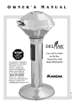
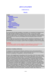
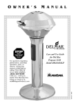
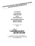
AERONAUTICAL DESIGN SERVICE REPORT REPORT NO ADS 100517-1-14 PROJECT: COMANCHE STABILATOR HORN APPROVAL Assembly Instructions Comanche Stabilator Horn Revisions Notes This report at its latest revision status superseded all previous revisions. Only a total reprint of the report promulgates revisions. All pages bear the same revisions/date status Rev No. Revision Date 0 1 2 3 4 5 2 Nov 2010 9 Nov 2010 14 Nov 2010 17 Nov 2010 24 Mar 2011 6 4 Apr 2011 1. Scope Signature Details of Change Original Issue Significant Revision Following LAME evaluation. Insert Step to Hone Large bore of the Stab Horn if Required. Incorporation of Suggestions Following Trial Installation Administrative Changes: Correction of Typos Corrected Bolt Orientation in Steps 76 and 78, Added Step 80 to apply torque seal, added requirement to paint a reference mark on the torque tube during disassembly Corrected LOCTITE References in Step 78. Added requirement to clean out the hole in Step #42 , and #48 (corrections marked [ XXX ]) This document provides instructions for the following activities: • Drilling a Replacement Stabilator Horn to suit an existing Torque Tube • Assembly of a Balance Arm into a Replacement Stabilator Horn to form a Stabilator Horn Assembly • Assembly of a Stabilator Horn assembly onto a Torque Tube. Activities involved with removing and refitting components which are part of existing operations that are covered by the normal Piper Maintenance instructions are not addressed in this document except by reference to complete the operations. 2. Required Items Item Comanche Stabilator Torque Tube Comanche Stabilator Balance Arm Qty 1 1 Stabilator Horn Bolt (AN5C-34A) Bolt (AN4C-22) 1 2 1 P/No ADS1008020828 AN5C-34A AN4C-22A PAGE 1 OF 27 Comments From Aircraft From Aircraft From Horn Kit From Horn Kit From Horn Kit AERONAUTICAL DESIGN SERVICE REPORT REPORT NO ADS 100517-1-14 PROJECT: COMANCHE STABILATOR HORN APPROVAL Washer 5/16” Thin Washer ¼” Regular Nut 5/16” Self Locking Low Ht Nut ¼” Self Locking Regular Nut 5/16” UNF Plane Nut ¼” UNF Plane 2 2 2 1 2 1 AN960L-516 AN960-416 MS21083N-5 MS21044-4 AN315-5 AN315-4 From Horn Kit From Horn Kit From Horn Kit From Horn Kit Used In Assembly Process, From Shop Supplies Used In Assembly Process, From Shop Supplies Tooling Bush (5/16” Diameter) Drill (19/64”dia with 3/16” dia Pilot ) Reamer (5/16” dia with 3/16” dia Pilot) Pin Locating ( 3/16” Diameter) Pin Locating ( ¼” Diameter) 1 1 1 1 1 ADS 1007220811 ADS 1007221136 ADS 1007221250 ADS100723-639 ADS 1007230930 From Installation Kit From Installation Kit From Installation Kit From Installation Kit From Installation Kit Permanent Marker Lint Free Cloth LOCTITE Retaining Compound Stick LOCTITE Retaining Compound Liquid LOCTITE PRIMER LOCTITE Cleaner Degreaser Heat Gun TFT Brake Cylinder Hone Light Machine Oil Heating oven AR AR Stick Bottle EA EA 1 1 AR ea Heat Resistant Gloves 3M ROLOC Abrasive Embedded Nylon Wheel Emery Tape Pr ea AR 3. LOCTITE 668 LOCTITE 609 LOCTITE 7471 ODC-Free Cleaner & Degreaser TF6806 WD40 / Inox Fine Grade 25mm Wide , 120 grit Workshop Supply Workshop Supply Local Procurement Local Procurement Local Procurement Local Procurement Workshop Supply Local Procurement Local Procurement Workshop Supply Capable of maintaining 200degC +/- 10deg C for 30 minutes Workshop Supply Local Purchase Workshop Supply Referenced Documents FAA AC43-13-1b PA24 Comanche Service Manual Twin Comanche Service Manual ADS 1010250948 ADS 1007220811 ADS 1007221324 Document Manual Manual Drawing Drawing Drawing PAGE 2 OF 27 Advisory Circular Acceptable, Techniques, and Practices – Aircraft Inspection and Repair Piper Publication Number 753-516. Piper Aircraft Publication 753-645 Stabilator Horn Assembly Drawing Tooling Bush 5/16” Dia Long Tooling Bush 5/16” Dia Short (Tapered One End) AERONAUTICAL DESIGN SERVICE REPORT REPORT NO ADS 100517-1-14 PROJECT: COMANCHE STABILATOR HORN APPROVAL ADS 1007230639 ADS 1007230930 ADS 1010255555 4. Drawing Drawing Alignment Key 3/16” Diameter Alignment Key ¼” Diameter Instructions 4.1. Preliminary Operations required to gain access to install the Replacement Stabilator horn Note: Each of the operations described in this section are standard operations which are described in the relevant Piper Service Manual for the aircraft. Please refer to the Piper Manuals for instructions on how to complete these operations. 1. 2. 3. 4. 5. 6. 7. 8. 9. 10. Remove the aft fuselage access panel forward of the RH Stabilator. Remove the fuselage tail fairing. Disconnect the stabilator control cables from the stabilator horn assembly. Remove the balance weight from the arm. Remove the bolt from the stabilator rear spar. Remove the four bolts attaching the stabilators to the stabilator torque tube assembly. Remove the stabilators from the torque tube assembly. Remove the stabilator bearing block reinforcement channels. Remove the two bolts holding the stabilator tab control bellcrank assembly to the bearing blocks. Remove the Torque Tube Assembly with the Bearing Blocks in place from the aircraft in accordance with the relevant Piper Service Manual. 4.2. 11. Remove the Old Horn Assembly from the Torque Tube Remove all paint and rust from the outer surface of the torque tube. Coat the torque tube with a light oil to aid the removal of the various components. Note: During the removal of components from the torque tube assembly, note the relative position of the components to help reassembling them correctly. In particular note the orientation of the stabilator horn and balance arm and paint a reference mark on the PAGE 3 OF 27 AERONAUTICAL DESIGN SERVICE REPORT REPORT NO ADS 100517-1-14 PROJECT: COMANCHE STABILATOR HORN APPROVAL end the of the tube to show the direction of the balance arm. 12. Remove both Bearing Blocks (Items H and L on diagram) Note the position of any shims, Record the thickness and location for later reinstallation 13. Remove the Collar Assembly ( Item J on diagram) 14. Look up inside the Torque Tube to visually inspect the exposed sections of the stabilator horn attaching bolts for corrosion. Use 120 grit emery tape to remove the corrosion if present on the bolts. Note: All original nuts and bolts used in the torque tube assembly are to be discarded. 15. 16. Remove the two bolts attaching the Stabilator Horn to the Torque Tube. Remove the Stabilator Horn Assembly by sliding along the Torque Tube. Note: It may be necessary to heat the Stabilator horn to relieve any interference between the horn and the torque tube 17. Service the Torque Tube in accordance with the Piper Maintenance Instruction and replace if required. PAGE 4 OF 27 AERONAUTICAL DESIGN SERVICE REPORT REPORT NO ADS 100517-1-14 PROJECT: COMANCHE STABILATOR HORN APPROVAL 4.3. Remove the Balance Arm from the Stabilator Horn Assembly 18. Remove the ¼inch bolt attaching the Balance Arm to the horn. 19. Withdraw the Balance Arm from the stabilator horn. Note: The joint between the Balance Arm and the Stabilator Horn is an interference fit. Use of heat and a puller (P/No ADS 101025555 or similar) may be necessary to withdraw the arm from the horn. As the horn will not be refitted there is no concern about damaging the horn during this operation. The Balance Arm is reused therefore exercise caution to prevent damage to the Arm during this operation. 20. Visually inspect the Balance Arm internal and external surfaces looking for : • corrosion, • evidence of cracking, • other damage Warning: Replace the Balance Arm, or seek further engineering appraisal if there is evidence of cracking. 21. Light surface corrosion may be removed using a 3M Abrasive Impregnated Nylon Wheel (ROLOC) Fine Grade. ( or Similar Alternative) Material removal up to 0.15mm (0.005”) is acceptable. PAGE 5 OF 27 AERONAUTICAL DESIGN SERVICE REPORT REPORT NO ADS 100517-1-14 PROJECT: COMANCHE STABILATOR HORN APPROVAL 22. Seek further engineering evaluation if the depth of material removed exceeds this amount at any location on the shaft. Dress the end of the Balance Arm in the area where it is inserted into the Stabilator Horn. Remove any debris, or material which has adhered to the surface of the Balance Arm from the interference fit in the previous installation. Note: Use Fine Grade 3M Impregnated nylon wheel, or 600 grit abrasive papers. On completion ensure that the surface is “smooth”, uniform and free from any obtrusions. 23. Wipe the surface of the Balance Arm with light machine oil if reassembly will not occur within 60 minutes to prevent the surface from corroding. 4.4. 24. Prefit the Stabilator Horn to the Balance Arm Identify the bore diameter of the new Stabilator Horn which is written on the release sheet for and write this in each of the six lines under the column heading “Bore Diameter” in Table #1 which is included at Step 25. PAGE 6 OF 27 AERONAUTICAL DESIGN SERVICE REPORT REPORT NO ADS 100517-1-14 PROJECT: COMANCHE STABILATOR HORN APPROVAL 25. Use a 25 to 50mm (1 to 2 inch) micrometer to measure the outside diameter of the Balance Arm at the six locations “D”, “E”, “F”, “J”, “K”, and “L” shown in Figure #1, and Figure #2. Record the readings in the Table #1 Note: Required Measurement Accuracy 0.0005” (0.02mm) Figure 2 Parallel to the plane of the ¼” bolt Figure 1 Perpendicular to the plane of the ¼” Bolt Table 1 Location 26. Shaft Diameter (mm) (Measured) Bore Diameter (mm) (Copied from Release Certificate) Interference = (Shaft Diam)- (Bore Diam) D E F J K L Complete each line in Table #1 by calculating the level of interference at each of the six locations using the following relationship: ܵ = ݁ܿ݊݁ݎ݂݁ݎ݁ݐ݊ܫℎ݂ܽ ݎ݁ݐ݁݉ܽ݅ܦ ݐ− ݎ݁ݐ݁݉ܽ݅ܦ ݁ݎܤ PAGE 7 OF 27 AERONAUTICAL DESIGN SERVICE REPORT REPORT NO ADS 100517-1-14 PROJECT: COMANCHE STABILATOR HORN APPROVAL 27. The allowable level of Interference is within the range 0.000” to 0.002” (0.00mm to 0.05mm). Note: This level is interference applies to each measurement, and is not an “Average Value” • 28. If Interference is in the range 0.000” to 0.002” (0.00mm to 0.05mm) o Interference is acceptable, proceed to Step 31 in this assembly sequence • If Interference is less than 0.000”. (i.e. a negative number) o Interference is unacceptable and recovery from this condition is not included in this set of installation procedures o Replace Balance Arm, or o Seek Engineering Dispensation. Contact Alan Kerr [email protected] • If interference is higher than 0.002” (0.05mm) o The level of interference is unacceptable but can be recovered by honing the bore. o Got to Step Error! Reference source not found. For recovery instructions. Copy the values for “D”, “E”, “F”, “J”, “K”, and “L” from Table #1(above) into the Shaft Diameter Column in Table #2 (below). Table 2 Location Shaft Diameter (mm) Bore Diameter (mm) Interference (Measured) = (Shaft Diam)- (Bore Diam) (Copied from Table #1) Entrance Mid Depth Full Depth Entrance Mid Depth Full Depth D E F J K L A B C G H I PAGE 8 OF 27 AERONAUTICAL DESIGN SERVICE REPORT REPORT NO ADS 100517-1-14 PROJECT: COMANCHE STABILATOR HORN APPROVAL 29. Uniformly hone the Balance Arm bore in the Stabilator Horn to enlarge the diameter using the TF6806 hone. o Check the diameter regularly at the 6 locations “A”, “B”, “C”, “G”, “H”, “I” Figure #3, and Figure #4. o Record these values in Table #2 which is included in Step 28 o Calculate the level of interference o Continue honing as required Note: Diameter variation is not to exceed 0.001” (0.03mm) Warning: Be careful when honing to ensure that the diameter along the length of the bore is uniform and not tapering. A tapered bore will make it more difficult to insert the balance arm into the horn. Make the measurements regularly and adjust the honing technique to achieve this Figure 3 Figure 4 PAGE 9 OF 27 AERONAUTICAL DESIGN SERVICE REPORT REPORT NO ADS 100517-1-14 PROJECT: COMANCHE STABILATOR HORN APPROVAL 30. If there has been a need to hone the bore then measure and record the final dimensions of the bore at the 6 locations “A”, “B”, “C”, “G”, “H” and “I” in Table #4, and confirm that the level of interference is acceptable. Ref Figure #1, Figure #2, Figure #3, and Figure #4. Table 3 Location Entrance Mid Depth Full Depth Entrance Mid Depth Full Depth 31. 32. Bore Diameter (mm) Interference (Copied from Table #1) (Final Measurements) = (Shaft Diam)- (Bore Diam) D E F J K L A B C G H I Verify that the 0.25” dia Pin Locating from the installation kit is a running fit in the Stabilator Horn and the Balance Arm and will traverse through both sides of the component with only mild resistance. Ream the hole if required to achieve a running fit. Inspect the 28mm Balance Arm bore in the Stabilator Horn, to ensure that it is clean and free from any machining burs. Remove any burs present by hand abrasion using 320 grit abrasive paper or similar methods. 4.5. 33. Shaft Diameter (mm) Prefit the Stabilator Horn to the Torque Tube Torque Tube: 1. Examine the external Surface of Torque Tube for any surface defect which will prevent the new Stabilator Horn from being fitted. Corrosion, burrs, and bruising of the ends are examples of such defects. Note: Any assessment of the serviceability of the Torque Tube is to be made in accordance with the maintenance instructions provided in the relevant PIPER Maintenance Manuals and Service Bulletins for the aircraft 2. Blend any defects which are found to ensure a smooth surface. a. These blending operations will remove the plating which is applied to the Torque Tube for corrosion resistance. Blended areas will need to be treated before final PAGE 10 OF 27 AERONAUTICAL DESIGN SERVICE REPORT REPORT NO ADS 100517-1-14 PROJECT: COMANCHE STABILATOR HORN APPROVAL assembly. Note: All blending and treating operations are to be done in accordance with the Piper Maintenance Manuals 3. Lightly lubricate the outside surface of the Torque Tube over which the Stabilator Horn will pass, with light machine oil 34. 35. Stabilator Horn 1. Examine the inside surface of the bore in the Stabilator Horn that will mate with the Torque Tube. 2. Verify that the bore is clean, and free from any paint, or primer 3. Verify that there are no burrs on any of the edges or scratches in the bore. 4. Lubricate the bore with Light machine oil Stabilator Horn to Torque Tube Fit Note: The fit between the Stabilator Horn and the Torque Tube should be a snug fit which can be assembled by hand. Check that the Stabilator Horn can be slide over the Torque Tube by hand without the need for presses or the application of heat. 36. If this snug fit cannot be achieved then carefully, and evenly hone the bore in the Stabilator Horn until this snug fit is achieved. A maximum clearance of 0.002” (0.05mm) between the Outside Diameter of the Torque Tube and the Inside Diameter of the mating hole in the Stabilator Horn is allowed. Secure the Torque Tube in a soft jaw vice on the side with the collar. Note: Experience has shown that it is possible to permanently deform the Torque Tube, particularly the Torque Tube from single engine Comanche’s, when clamping in a vice. Use of the clamping Collar (ADS 1011031045) or similar fixture is recommended to reduce the risk of permanently deforming the Torque Tube. 37. Insert a 5/16” dia Tooling Bush P/No ADS 1007220811 into each of the two stabilator horn attachment holes in the torque tube. Note: Position the bush centrally in the tube with respect to the faces on the PAGE 11 OF 27 AERONAUTICAL DESIGN SERVICE REPORT REPORT NO ADS 100517-1-14 PROJECT: COMANCHE STABILATOR HORN APPROVAL tube and ensure that the outside faces of the bush are sub-flush with the surface of the torque tube. Linish the ends of the bushes if necessary to achieve this . 38. Slide the stabilator horn over the torque tube until the attachment holes are approximately aligned with the holes in the torque tube. Note#1: The Replacement Stabilator Horn is supplied with 3/16” Diameter pilot holes. On Assembly these holes will be used to align the horn with the tooling bushes fitted into the Torque Tube. Note #2: The replacement horn is symmetrical. There is no preferred alignment for the upper and lower faces. Note #3: Manufacturing tolerances on the horn and the Torque Tube are such that there may be a slight interference between the components. If this is the case then it may be necessary to heat the horn to allow this operation to be completed. PAGE 12 OF 27 AERONAUTICAL DESIGN SERVICE REPORT REPORT NO ADS 100517-1-14 PROJECT: COMANCHE STABILATOR HORN APPROVAL 39. Roughly align the horn by eye, looking through a pilot hole on the horn, then insert the locating pin P/No ADS1007230639 to achieve correct alignment of the horn with the tube. PAGE 13 OF 27 AERONAUTICAL DESIGN SERVICE REPORT REPORT NO ADS 100517-1-14 PROJECT: COMANCHE STABILATOR HORN APPROVAL 40. Check the alignment of the opposite hole, then use the 19/64” dia Drill with the 3/16” dia pilot to open out both ends of the hole in the Stabilator Horn which is opposite to the pin. Note: If there is misalignment between the pilot hole in the Stabilator Horn, and the hole in the Tooling bush, you can open up the hole in the Stabilator horn by hand drilling with a 13/64” dia drill. If you are still unable to start the pilot in the Tooling Bush, then the misalignment is inacceptable and cannot be recovered using the instructions provided in this procedure. Seek further engineering dispensation before proceeding. Ensure that the drill travels in as far as possible with the bushes inserted: It doesn’t matter that the bushes may be damaged. PAGE 14 OF 27 AERONAUTICAL DESIGN SERVICE REPORT REPORT NO ADS 100517-1-14 PROJECT: COMANCHE STABILATOR HORN APPROVAL 41. Use the 5/16” dia chucking reamer with the 3/16” dia pilot to ream the holes to the final diameter. 42. Again ensure that the ream extends as far as possible into the hole with the bushes inserted Withdraw locating pin, and slide the Stabilator Horn down the torque tube far enough to remove the tooling bush. [After removing the tooling bush, use the reamer to clean out the base of the hole on both sides of the torque tube. ] 43. Slide the Stabilator Horn back up the Torque Tube, PAGE 15 OF 27 AERONAUTICAL DESIGN SERVICE REPORT REPORT NO ADS 100517-1-14 PROJECT: COMANCHE STABILATOR HORN APPROVAL 44. Align the holes then fit a 5/16” dia bolt into the finished hole. Fit an AN315-5 or equivalent free running nut and nip up finger tight to secure the assembly Note: Use a plane nut (not a self locking nut). Nip up the nut but do not tighten at this stage. 45. Drill and ream the both ends of the 5/16” dia hole on the other side to where the bolt is installed. 46. As before ensure that the drill travels through the horn and onto the bush. Repeat the drilling and reaming operations on the opposite end of this hole. PAGE 16 OF 27 AERONAUTICAL DESIGN SERVICE REPORT REPORT NO ADS 100517-1-14 PROJECT: COMANCHE STABILATOR HORN APPROVAL 47. 48. 49. 50. Use a Spirit Marker to mark the location of the edges of the stabilator horn on the surface of the Torque Tube. Remove the 5/16” dia Bolt and Slide the horn off the Torque Tube. [Use the reamer to clean out the base of this latest hole on both sides of the torque tube.] Examine the holes in the horn. 1. Check that the hole has been correctly reamed to full depth 2. Clear the holes with the reamer if necessary Debur the internal edge of the finished hole using a small fine SCOTHBRITE disc on a “Dremel” or die grinder. PAGE 17 OF 27 AERONAUTICAL DESIGN SERVICE REPORT REPORT NO ADS 100517-1-14 PROJECT: COMANCHE STABILATOR HORN APPROVAL 1. Examine the internal edge visually and by feel to ensure that the edge is free from burrs and has a smoothly polished radius. 2. No specific dimension is placed on this radius, however it should be between R0.25mm and R0.5mm. PAGE 18 OF 27 AERONAUTICAL DESIGN SERVICE REPORT REPORT NO ADS 100517-1-14 PROJECT: COMANCHE STABILATOR HORN APPROVAL 4.6. 51. 52. 4.7. Surface Finish the Stabilator Horn Verify that all machining operations have been completed on the Stabilator Horn and that all traces of swarf are removed from the component. Treat the surface of the Stabilator Horn with Alodine 1200 or similar product in accordance with the process instructions provided by HENKEL for ALODINE 1200 or similar instructions provided by the manufacturer of an alternate chemical. Assemble the Balance Arm to the Stabilator Horn WARNING: Assembling the joint between the Balance Arm and the Stabilator Horn is a process which requires speed and experience. If the process is not done correctly or if any unforeseen problems occur during the assembly then it is likely that the joint will lock before the Balance Arm is fully inserted into the horn. If this occurs you will need to use a heat gun to apply heat to the horn and use the puller to withdrawn the Balance Arm from the horn and start the process again. Suggestion: If this is the first time that you are attempting this assembly, then it is suggested that you have at least one DRY practice run, using the original horn. Do Not apply the LOCTITE for the practice run. Suggestion: It is suggested that assembling the Balance Arm into the Stabilator Horn be done using two people; one person to remove the horn from the oven and insert it over the balance arm, and one person to direct the alignment of the horn with the balance arm, and insert the pin. PAGE 19 OF 27 AERONAUTICAL DESIGN SERVICE REPORT REPORT NO ADS 100517-1-14 PROJECT: COMANCHE STABILATOR HORN APPROVAL 53. Clean the 28mm bore by wiping with a clean lint free cloth moistened with LOCTITE Cleaner Degreaser 54. Apply LOCTITE Primer (Product 7649 to the surface of the bore, and allow to dry) 55. Clean the mating surface of the balance arm using a clean lint free cloth moistened with LOCTITE Cleaner Degreaser. PAGE 20 OF 27 AERONAUTICAL DESIGN SERVICE REPORT REPORT NO ADS 100517-1-14 PROJECT: COMANCHE STABILATOR HORN APPROVAL 56. 57. 58. Apply LOCTITE primer 7649 to the mating surface of the Balance Arm and allow to dry. Preheat the oven to 200degC +/- 10degC. ( 400degF +/- 20degF), then place the Stabilator Horn in the oven and allow to heat soak for 20 minutes. Stand the Balance Arm in a vertical orientation and secure using a soft jawed vice. Orientate the balance arm so that the axis of the ¼” hole is pointing outward from the vice. PAGE 21 OF 27 AERONAUTICAL DESIGN SERVICE REPORT REPORT NO ADS 100517-1-14 PROJECT: COMANCHE STABILATOR HORN APPROVAL 59. Coat the mating surface of the Balance Arm with LOCTITE 668 Retaining Compound o 100% coverage up to 50mm (2inches) from the end of the tube 60. 61. Remove the horn from the oven. Hold the horn above the end of the Balance Arm and rotate the horn to obtain a correct alignment of the ¼ inch hole in the horn with the ¼ inch hole in the Balance Arm. 62. Quickly lower the horn onto the Balance Arm until it bottoms on the arm. Note: you may need to rotate the horn backwards and forwards to assist the sliding motion when inserting the horn. Don’t forget PAGE 22 OF 27 AERONAUTICAL DESIGN SERVICE REPORT REPORT NO ADS 100517-1-14 PROJECT: COMANCHE STABILATOR HORN APPROVAL to work quickly! 63. Rotate the horn to obtain the correct alignment and insert the alignment pin. Note: you may need to raise the horn slightly (about 3mm (0.125inches) ) to insert the alignment pin. The tapered end of the alignment pin will assist with this movement. If there is a misalignment of the holes in the Balance Arm and the Torque Tube it may not be possible to insert the alignment pin all the way through the assembly. In this case insert the pin a far as possible to force the best alignment. 64. 65. 66. 67. 68. Allow the assembly to cool to room temperature. Remove excess LOCTITE from around the joint. Allow the joint to stand for at least 30 minutes for the LOCTITE to cure before moving the assembly. Remove the ¼ inch alignment pin. If there was a problem inserting the alignment pin, then ream the hole with a ¼” reamer so that an AN4 bolt will pass through both sides of the joint. 4.8. 69. 70. 71. 72. Assemble the Stabilator Horn onto the Torque Tube Solvent Wipe the external surface of the torque tube using a clean lint free rag moistened with LOCTITE Cleaner Degreaser. Do not remove the marker lines. Note: Clean the area where the horn will be bolted and the section of the Torque Tube over which the Stabilator Horn will pass. Clean the internal bore of the Stabilator Horn, with a clean lint free cloth moistened with LOCTITE Cleaner degreaser. Apply LOCTITE 668 to the surface of the Torque Tube between the marker lines. 100% coverage is required. Slide the Stabilator Horn onto the tube until the leading edge is close to the first of the marker lines. Note; Do Not slide past this point at this time. Monitor the orientation such that the holes in the Stabilator Horn and the Torque Tube will align when the two items are finally PAGE 23 OF 27 AERONAUTICAL DESIGN SERVICE REPORT REPORT NO ADS 100517-1-14 PROJECT: COMANCHE STABILATOR HORN APPROVAL positioned. 73. 74. 75. 76. 77. Apply LOCTITE 668 as a 15mm wide band below the heads of the AN5-34A bolts. Apply LOCTITE 609 onto the surfaces of the 5/16 hole in the Stab-Horn and Torque tube, on rear side of the stab horn. (i.e. the side away from the balance arm). Use a rotating motion correctly align the holes then slide the Stabilator Horn into position . Install AN5-34A bolts from the front of the horn until fully seated on the horn. Fit MS21083N-5 nuts and AN960L-516 washer. Torque nuts to 60 to 85 inch pounds. (ADS Dwg 1010250946 Refers). PAGE 24 OF 27 AERONAUTICAL DESIGN SERVICE REPORT REPORT NO ADS 100517-1-14 PROJECT: COMANCHE STABILATOR HORN APPROVAL 78. Coat the shank of the bolt 15mm from the head with LOCTITE 668 prior to installation. Install theAN4-22A Bolt , MS21044-4 nut and AN906-416 Torque Nut to 30 to 40 inch-pounds. (ADS Dwg1010250946 refers). 79. Allow the LOCTITE to cure 4.9. 80. 81. 82. Torque Tube Assembly Finishing Operations Apply “Torque Seal” to all nuts after tightening. Apply PR1422 (PROSEAL) or similar to • seal the edges of all of the joints between the stabilator horn and the torque tube. • all the exposed bolt heads and nuts • bolts on the inside of the tube as well Repaint the torque tube assembly in the region between the two collars on the torque tube. Include the stabilator horn, and the balance arm. Note: This painting should use paint which is approved for use on aircraft, and is applied in accordance with the paint manufacturer’s specifications. PAGE 25 OF 27 AERONAUTICAL DESIGN SERVICE REPORT REPORT NO ADS 100517-1-14 PROJECT: COMANCHE STABILATOR HORN APPROVAL 4.10. Final Assembly 83. Note: The LOCTITE will require 3 hours at Room Temperature to set to a condition when the assembly can be moved and 24 hours at room temperature to cure before the aircraft can be flown. 84. 85. 86. Reinstall the torque tube assembly on the aircraft in accordance with the relevant Piper Service Manual for the aircraft. Install the Left hand and Right hand stabilator halves in accordance with the relative Piper Service Manual for the aircraft. Install the stabilator mass Balance in accordance with accordance with the relative Piper Service Manual for the aircraft. 4.11. Balance the Stabilator 87. Balance the Stabilator in accordance with the Balancing procedures specified the applicable Piper Comanche Service Manual. Note: Having the stabilator correctly balanced cannot be overemphasised. Installation of the replacement horn has the potential to change the balance. It is important therefore to check that the stabilator is correctly balanced. 88. Reconnect the stabilator control cables. 4.12. Stabilator Travel Check 89. Check the stabilator, and stabilator trim rigging in accordance with the rigging requirements that are stated in the applicable service manual. Adjust as required. Torque bolts per fine thread series torque tables in the “Handling and Servicing” Section of the service manual. Note: Installation of the replacement stabilator horn has the potential to alter the rigging. DO Not omit this step from the installation procedures PAGE 26 OF 27 AERONAUTICAL DESIGN SERVICE REPORT REPORT NO ADS 100517-1-14 PROJECT: COMANCHE STABILATOR HORN APPROVAL 4.13. Documentation 90. Use the data below to record the changes in the Record of Weight alterations for the aircraft. Aircraft Model Weight Adjustment PA24 PA24-250, PA24-260, PA24-400 PA-30, PA-39, PA-40 91. 92. 0.2 kg (0.44 lbs) 0.2 kg ( 0.44 lbs) Arm Distance Behind Datum 6720mm (264.5 inches) 6670 mm (262.5 inches) Make a log book entry to record the installation of this replacement stabilator horn. Record the following details and email to [email protected] Company Who Installed the horn Date of Installation Aircraft Registration Aircraft Model Serial Number of Stabilator Horn Name of the Registered Owner of the aircraft Contact Details for aircraft owner Address Line 1 Address Line 2 Town/Suburb State Zip Code Country Email address Phone Number PAGE 27 OF 27 Aircraft Serial Number Aircraft TSN (hours) Filename: ADS 100517-1-14 (Rev 6) Installation Instructions (ID 4105) Directory: C:\Users\apk\Documents Template: C:\Users\apk\AppData\Roaming\Microsoft\Templates\ADS Report Template.dot Title: Structural Repairs Approval Subject: Author: apk Keywords: Comments: Creation Date: 5/04/2011 10:53:00 AM Change Number: 5 Last Saved On: 5/04/2011 11:05:00 AM Last Saved By: apk Total Editing Time: 14 Minutes Last Printed On: 5/04/2011 11:06:00 AM As of Last Complete Printing Number of Pages: 27 Number of Words: 3,973 (approx.) Number of Characters: 22,651 (approx.)