1
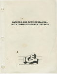
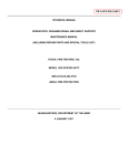
PRICE $2.00
MODEL PA500M*
AMPLIFIER
SERVICE MANUAL
SECTION I
GENERAL DESCRIPTION
The standard operating functions of this siren are
Wail, Tap II, Yelp and manual peak-and-hold. The
Tap II feature allows the driver to change the siren
sound from wail to yelp via the vehicle’s horn ring.
Tap II provides an especially effective traffic clearing
capability.
The siren also has provisions for public address
(PA) operation. An optional Federal Model MNCT
Microphone is required if it is desired to make use of
the PA capability.
Its splashproof enclosure complies with SAE
specification J1211 for splashproof testing. Available
shock and vibration mounting hardware make it an
ideal choice for a motorcycle siren. Installation
instructions are contained in a separate document
included with this siren.
Figure 1. Model PA500 Amplifier.
The Federal Model PA500M* Amplifier is a
precision built, reliable electronic siren incorporating
state-of-the-art CMOS technology. The siren operates from a nominal 12Vdc, negative ground, electrical system. It is capable of operating with one 58watt speaker or one 100-watt speaker. (Model
PA500M* comes factory set for a 58-watt output.)
The factory set output can be changed, as described
in Section IV of this manual.
The siren’s power/control cable is terminated
with bullet connectors. These connectors mate with
connectors from the control head, power source and
speaker to provide a quick, easy installation. Also,
the unit’s slide-in/out design facilitates servicing.
-1-
SECTION II
SPECIFICATIONS
Input Voltage .
.
.
.
.
.
.
.
.
.
11Vdc to 16Vdc
Polarity
.
.
.
.
.
.
.
.
.
Negative ground only
.
.
.
.
.
.
.
.
.
30mA ± 5mA
Operating Temperature Range .
.
.
.
.
.
-30°C to +65°C
Operating Current (14Vdc, Wail) .
.
.
.
.
4.5 amperes (58 watt)
7.0 amperes (100 watt)
Frequency Range .
.
.
.
.
.
.
.
.
500 to 1500Hz
Cycle Rate
.
.
.
.
.
.
.
.
Wail - 12 cycles/minute (nominal)
Yelp - 180 cycles/minute (nominal)
Voltage Output (approx.)
.
.
.
.
.
.
.
45V p-p (58 watt)
60V p-p (100 watt)
Audio Frequency Range
.
.
.
.
.
.
.
300 to 10KHz
Harmonic Audio Distortion (300-3KHz)
.
.
.
10% max. all power levels from 1/2 to 50 watts
Input Voltage Required to Obtain 15Vrms
across Speaker Load .
.
.
.
0.5Vrms
Dimensions (HWD - less mtg. brkt.)
.
.
.
.
3.05" x 4.36" x 6.38"
Net Weight
.
Standby Current
.
.
.
.
.
.
.
.
.
.
.
.
4-1/2 pounds
Shipping Weight
.
.
.
.
.
.
.
.
.
6-1/2 pounds
-2-
SECTION III
CIRCUIT DESCRIPTION
neously, control pin IC5C-pin 6 goes to a logic “1” and
allows the siren to charge at a yelp rate until the
tone peaks.
Refer to the block diagram (figure 2) and schematic diagram (figure 3) while reading this section.
3-1.RATE OSCILLATOR AND VOLTAGE
CONTROLLED OSCILLATOR.
IC1, a phase-locked loop, contains the voltage
controlled oscillator. C8, R1, R5, R13 and the control
voltage on IC1-pin 9 determines the output frequency. As the siren coasts down in the manual
mode, the output of the VCO must be disabled to
prevent frequencies lower than 350Hz from damaging the amplifier’s output transistors. IC2, a voltage
comparator, compares the VCO control voltage to the
low frequency reference voltage set by R15 and R23.
When the VCO control voltage drops below the
reference, IC2-pin 7 goes to a logic “1” through OR
gate IC4B. The VCO is also inhibited when the
microphone push-to-talk input is selected. This logic
level is gated through IC8D and IC4B to the VCO
inhibit pin.
The rate oscillator and voltage controlled oscillator (VCO) sections are the “heart” of the Model
PA500 circuitry. Not only does the rate oscillator
determine the cycling rate of each siren tone, but it
also generates the control voltage that operates the
VCO. The VCO generates a square-wave output
whose frequency is directly proportional to the
control voltage. The output of the VCO is coupled to
the siren preamplifier.
The siren rate oscillator consists of an LM555
timer configured as an astable oscillator. The astable
oscillator (IC3) employs an analog switch (IC5C) to
select the RC timing network which determines the
astable oscillator’s timing rate. IC5B, another analog
switch, connects the discharge pin of IC3 to the RC
timing network. When the peak function is called for,
the control pin IC5-pin 5 goes to a logic “0” putting
the switch in a high impedance state (OFF). Simulta-
3-2.SIREN MODE CONTROL.
The wail mode is controlled by a logic “0” at
IC8A. Through IC8A, the astable oscillator is enabled
and the wail function is produced. While the wail
mode is activated, the yelp mode may be selected by a
logic “0” at IC8C. Through IC7 and IC8, flip-flop IC6
changes state and brings control pin IC5-pin 6 to a
logic “1” thus switching in the necessary RC network
to produce the yelp signal.
The manual mode is enabled with the siren in the
standby mode and IC8C-pin 11 at a logic “0”. IC4C,
IC5B, IC5C and IC7B provide the necessary decoding
for the manual mode.
3-3.AUDIO SECTION.
The amplifier system consists of MOSFET/
Bipolar complementary voltage and power gain
amplifiers. The circuit consisting of Q5, Q6, Q7 and
Q8 use both AC and DC feedback to insure stability
and maximum linear signal swing. The overall midband voltage gain is set by the ratio of feedback
resistor R43 and Q5 source resistor R16. Frequency
compensation is set by the combination of C3,R28
and C27.
Figure 2. Block Diagram.
-3-
Audio signal levels are coupled to the amplifier
through R41. An input voltage of approximately
250mV is required to drive the amplifier to full rated
sine wave power. This level is produced by the
transistorized MNCT* microphone in the PA mode.
thermistor RT1 and the voltage divider (R1 and R12)
across diode reference CR2. Q1 is used to switch the
bias “on” during PA messages.
3-4. POWER SECTION.
The amplifier enable line uses a relay (K1) to
disable the amplifier section, when neither siren or
PA functions are needed.
The ignition line supplies B+ to the printed
circuit board. Networks consisting of C18, CR6, CR7
and C17 provide input filtering for voltage regulator
LM7808. B+ from the battery supplies bias to the
output section consisting of T201, Q201 and Q202.
Temperature compensation and bias current for
minimizing crossover distortion is supplied by
SECTION IV
SERVICE AND MAINTENANCE
Carefully check all envelopes, shipping labels and
tags before removing or destroying them.
SAFETY MESSAGE TO PERSONNEL SERVICING
FEDERAL SIGNAL ELECTRONIC SIRENS
The lives of people depend on your safe servicing
of Federal products. It is important to follow all
instructions shipped with the products. In addition,
listed below are some other safety instructions and
precautions you should follow:
4-2. GENERAL.
Most of the electronic component parts used in
the PA500M* are standard items that are available
at almost any radio or electronics supply outlet.
•
Read and understand all instructions in
this manual before servicing this
equipment.
The factory can and will service your equipment
or provide technical assistance with problems that
cannot be handled satisfactorily and promptly locally.
•
To properly service an electronic siren, you
must have a good understanding of automotive electrical systems and emergency
signalling procedures.
•
All effective sirens and horns produce loud
sounds which may cause, in certain situations, permanent hearing loss. You should
take appropriate safety precautions such
as wearing hearing protection.
If any unit is returned for adjustment or repair,
it can be accepted only if we are notified by mail or
telephone in advance of its arrival. Such notice
should clearly indicate the service requested and give
all pertinent information regarding the nature of the
malfunction and, if possible, its cause.
•
Address all communications and shipments to:
Service Department
Federal Signal Corporation Signal Division
2645 Federal Signal Drive
University Park, IL 60466
In order for the electronic siren to function
properly, the ground connection must be
made to a solid chassis component and not
to an insulated point.
1-800-433-9132
When replacing small components, use care
when soldering. Heat easily damages integrated
circuits, transistors, capacitors and circuit boards.
Therefore, it is advisable to use a heat sink on the
component lead being soldered.
Failure to follow all safety precautions and
instructions may result in property damage, serious
injury, or death to you or others.
4-1. UNPACKING.
4-3. MODIFICATIONS.
After unpacking the siren, examine it for damage that may have occurred in transit. If the equipment has been damaged, file a claim immediately
with the carrier stating the extent of the damage.
The following paragraphs describe modifications
which can easily be made to the Model PA500M* by a
qualified service technician. Before any of the
-4-
3. Install jumper wire (JU1) at position
labeled SLOW PEAK.
modifications can be attempted, the front cover must
be removed. The screws which secure the front cover
to the housing should be removed with a 1/4-inch
wrench or flat blade screwdriver. Slide the chassis
out of the housing.
A.
4. Install a 100-ohm, 1/4watt, resistor at
position labeled CUTOFF.
5. Reinstall the PC board with the four
screws removed in step 1. Install J1, J2 and J3.
Insure that the polarization of the connectors is
correct.
Output Power Modification.
NOTE
The Model PA500M* comes factory set for a
58-watt output.
Locate the 12-position terminal strip on the
output PC board (see figure 5). Using a flat blade
screwdriver, move the orange wire to the described
position.
4-4. PA GAIN ADJUSTMENT.
The Model PA500M* comes from the factory
with the PA gain set to maximum. To decrease the
gain setting, proceed as follows (see figure 4):
TB201, pin 1 for 58-watt output.
TB201, pin 2 for 100-watt output.
B.
A. Remove the four screws which secure the
front cover to the housing. Slide the chassis out of
the housing.
Coast Down Elimination.
B.
The Model PA500M* comes from the
factory wired so that it will coast down after a siren
function has been deactivated. To eliminate the
coast down feature, and have the siren sound come to
an abrupt stop when the siren function is deactivated, proceed as follows (see figure 4):
C. Using a small flatblade screwdriver, rotate
R41 counterclockwise to a desired volume setting.
D. Reinstall the chassis in the housing and
secure the front cover.
1. Remove the main PC board by unplugging J1, J2, J3 and removing the four PC board
screws.
2.
Locate R41 (PA) on the main PC board.
4-5. TESTING.
After servicing, modification, or adjustment is
completed; perform a test of all functions to ensure
siren is operating properly.
Cut jumper wire (JU2) labeled FAST
PEAK.
-5-
-6Figure 3. Model PA500 Schematic Diagram.
Figure 4. Main Board Component Location Diagram.
Figure 5. Output Board Component Location Diagram.
-7-
PARTS LIST MODEL PA500 AMPLIFIER
Schematic
Symbol
Description
Schematic
Symbol
Part No.
*RESISTORS
R1
R2
R3
R4,7,17
R5,22
R6,18
R8
R9
R10
R11
R12
R13
R14
R15,28,43,
48,50
R16
R19,23
R20
R21,33,42,
44,47,49,
R24,25,30,
37,38,40
R26
R27,31
R29
R32
R34
R35
R36
R39
R41
R45
R46
68K Ohm, 5%
2200 Ohm
33 Ohm
10 Ohm
1.5 Megohm, 5%
150 Ohm
5600 Ohm
2700 Ohm
270 Ohm, 2 Watt, WW
8. 2 Ohm
27 Ohm
200K Ohm, Potentiometer
33K Ohm, 5%
1000 Ohm
100A261
100A221
100A288
100A251
100A726
100A238
100A253
100A206
103A128
100A743
100A250
106A203A-03
100A771
100A233
220 Ohm
100K Ohm, 5%
56K Ohm, 5%
10K Ohm
100A219
100A262
100A704
100A207
4700 Ohm
100A224
250K Ohm, Potentiometer
3300 Ohm
180K Ohm
150K Ohm
1000 Ohm, 2%
220K Ohm, 2%
15K Ohm, 5%
470 Ohm
10K Ohm, Potentiometer
68K Ohm, 5%
15 Ohm
105A255
100A209
100A706
100A226
100A712
100A719
100A239
100A255
105A263
100A261
100A291
C17
C22
C24,30,33,35
C29
C203
C204
Part No.
1000UF, 35V, Electrolytic
6.8UF, 15V, Tantalum
0.47UF, 35V, Tantalum
22UF, 16V, Electrolytic
0.001UF, 100V, Disc
500UF, 15V, Electrolytic
108A149
107A604
107A645
108A144
107A207
108A122
DIODES
CR1,2,3,4,5,7
CR6
CR8,9,10
CR201,202
CL-1 (ED3002S)
V18ZA3, Varistor
T155
1N5400
115B301
114A103
115B101
115A105
INTEGRATED CIRCUITS
IC1
IC2
IC3
IC4
IC5
IC6
IC7
IC8
IC9
Q1,7
Q2,3
Q4,6
Q5
Q8
Q201,202
108A153
108A147
107A771
107A767
120PF, 200V, Mono.
0.015UF, 100V, Poly.
3.9UF, 15V, Tantalum
10UF, 16V, Electrolytic
0.005UF, 100V, Disc
1.0UF, 50V, Tantalum
107A1004
107A766
107A642
108A143
107A211
107A649
128B079
128045
128A043A-04
128B082
128047
128A044
128B093
128A059
128A097
TIS92, NPN
2N6109, PNP
SD1124, FET
IRFD9123, FET
TIS93, PNP
2N5885, NPN
125B132
125B431
125A153
125A162
125B133
125B432
MISCELLANEOUS
CAPACITORS
330UF, 50V, Electrolytic
150UF, 16V, Electrolytic
0.001UF, Film
0.01UF, Film
MC14046BCP
LM358
LM555N
MC14071BCP
MC14066BCP
MC14027BCP
CD4093BE
MC14584B
UA78M08CKC
TRANSISTORS
*Unless otherwisc specified; all
RESISTORS are carbon type, ±10%, 1/4 Watt.
C2
C3,27
C4, 10,15,18
C5,6,11,
20,23,25,28
C7,12,31,32,34
C8
C9
C13,26
C14,201,202
C16,21
Description
CAPACITORS (Cont’d. )
T1
T201
RT1
TB201
J1
J2
J3,J201
K1
-8-
Transformer, Driver
Transformer, Output
Thermistor, 200-0hm
Terminal Strip, 12-position
Connector, Wafer, 4-pin
Connector, Wafer, 4-pin
Connector, Wafer, 8-pin
Relay, 12V, DPDT
PC Board, Main (without parts)
PC Board, Main (with parts installed)
PC Board, Output (without parts)
PC Board, Output (with parts installed)
120B145
120B140A-01
104A111
229A164
140A202
140A212
140A170
131A130A-01
130C339
200C906
130C338
200C905
255A205D
REV. D 995
Printed in U.S.A.