1
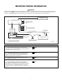
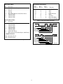
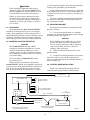
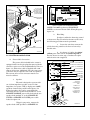
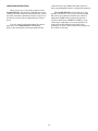
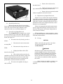
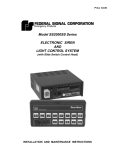
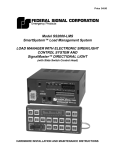
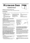
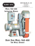
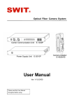
Price $4.00
Model SS2000-ERCSN1
ELECTRONIC SIREN
with
PARK-SIREN DEACTIVATION
INSTALLATION AND OPERATING INSTRUCTIONS
LIMITED WARRANTY
The Signal Division, Federal Signal Corporation (Federal), warrants each
new product to be free from defects in material and workmanship, under
normal use and service, for a period of two years on parts replacement and
one year on labor from the date of delivery to the first user-purchaser.
During this warranty period, the obligation of Federal is limited to repairing
or replacing, as Federal may elect, any part or parts of such product which
after examination by Federal discloses to be defective in material and/or
workmanship.
Federal will provide warranty for any unit which is delivered, transported
prepaid, to the Federal factory or designated authorized warranty service
center for examination and such examination reveals a defect in material
and/or workmanship.
This warranty does not cover travel expenses, the cost of specialized
equipment for gaining access to the product, or labor charges for removal
and re-installation of the product. Lamps, flash tubes, or batteries are not
covered under warranty.
This warranty does not extend to any unit which has been subjected to abuse,
misuse, improper installation or which has been inadequately maintained,
nor to units which have problems relating to service or modification at any
facility other than the Federal factory or authorized warranty service
centers.
THERE ARE NO OTHER WARRANTIES, EXPRESSED OR IMPLIED,
INCLUDING BUT NOT LIMITED TO, ANY IMPLIED WARRANTIES
OF MERCHANTABILITY OR FITNESS FOR A PARTICULAR
PURPOSE. IN NO EVENT SHALL FEDERAL BE LIABLE FOR ANY
LOSS OF PROFITS OR ANY INDIRECT OR CONSEQUENTIAL
DAMAGES ARISING OUT OF ANY SUCH DEFECT IN MATERIAL OR
WORKMANSHIP.
IMPORTANT WIRING INFORMATION
WARNING
The Federal SS2000-ERCSN1 is an advanced microprocessor based siren system. Unlike conventional siren systems, malfunctions and/or
improper operation WILL result if proper installation procedures are not followed. Refer to the accompanying diagram and pay special
attention to the "CHECK LIST" at the bottom of this page. To complete the electrical installation, refer to paragraph 3-5.
CONTROL HEAD
AMPLIFIER/RELAY UNIT
1
2
SIREN
+ BAT
RELAY SWITCHED
POWER TO LIGHTS
3
A
B
C
12
11
RELAY SWITCHED POWER
TO AUXILIARY DEVICES
D
10
CB1
CIRCUIT BREAKER
E
9
8
6
3
7
5
2
RED + 8/10AWG (MIN.)
4
BLK
AUXILIARY RELAY
50 AMP
50 AMP
1
GRN
VEHICLE CHASSIS
RED
FUSE BLOCK
20 AMP
SWITCHED IGNITION LINE CAPABLE
* OF CARRYING AN ADDITIONAL 20A.
- NEG
*
POS +
VEHICLE BATTERY
CHASSIS GROUND, AT FUSIBLE
LINK ON FRONT FENDER.
290A4053-01
CHECK LIST
1.
Is the red wire from the twelve pin connector (Pin 6)
connected to a point on the fuse block that is powered in run and
start positions? Use an in-line 20A fuse.
YES
2.
Is the black wire from the twelve pin connector (Pin 4)
connected to the fusible link at the front fender between the
negative (-) battery terminal and chassis ground? This is the
ONLY chassis ground allowed for this wire.
YES
3.
Is the green wire from the twelve pin connector (Pin 5)
connected to chassis ground?
YES
AUXILIARY RELAY/SIREN POWER:
4.
Is an 8/10 AWG wire connected to the load side of the
50/100-ampere circuit breakers? Route it through the hole
labeled +BAT on the amplifier/relay unit and attach it to LUG 1
on the circuit board. Use a 10 AWG wire with the 50-ampere
circuit breaker. Use an 8 AWG wire with the 100-ampere circuit
breaker.
YES
i
SECTION I
GENERAL DESCRIPTION
Any control head which conforms to the serial
interface definition in Section II, such as the
GE S825 Radio Control Head, may be used. Most
control heads of this type can be programmed to
provide the automatic, simultaneous light and siren
activation required by some laws. Momentary or
push-on/push-off relay operation is also provided. The
SS2000-ERCSN1’s flexibility allows variation of all of
these features during control head programming.
The SS2000-ERCSN1 may be installed in the
trunk, under the seat, or on the dash of any vehicle
with a 12 volt, NEGATIVE ground electrical system.
The siren circuits are protected from failure modes by
an in-line fuse that is replaceable without tools.
Relay outputs are protected by individual fuses.
Connection between the control head and the
SS2000-ERCSN1 is via a seven-conductor cable with
connectors at both ends for simple installation.
290A4053-02
Figure 1-1. Model SS2000-ERCSN1.
The Federal Model SS2000-ERCSN1 (figure 1-1)
is a full-featured electronic siren and light control
system. State-of-the-art microprocessor technology is
utilized to produce a small, compact, remotely
mounted unit. When combined with a properly
programmed control head, the SS2000-ERCSN1
provides a highly versatile electronic siren and light
system.
The SS2000-ERCSN1 can drive one or two
11-ohm impedance high power (100 Watt) or low
power (58 Watt) speakers. When two speakers are
used they must always be connected in parallel and
in phase.
The SS2000-ERCSN1 produces wail, yelp, and
hi-lo siren tones, as well as an air horn sound. A horn
ring transfer feature allowing horn ring control of
siren tones is available. Public address (PA) and
radio rebroadcast, as well as PA and radio rebroadcast volume adjustment, are provided by the control
head. In addition, eight relay outputs are available
for control of light bars, other auxiliary lights, and
accessories. A Park-Siren Deactivator, which deactivates all tones when the car is shifted into park, is
also included.
Other advanced features of the SS2000-ERCSN1
include:
All system functions must be controlled by a
user-supplied control head, usually mounted on or
near the dash of the vehicle. The SS2000-ERCSN1
communicates with the control head through a serial
interface as defined in Section II.
-1-
•
High degree of reliability and compact size
through the use of CMOS microprocessor and
other integrated circuits.
•
Simplified installation and service through
use of plug-in cables and printed circuit boards.
•
Relay outputs are individually fused with
standard automotive type fuses.
SECTION II
SPECIFICATIONS
AND
SERIAL INTERFACE DEFINITION
2-1. SPECIFICATIONS.
Input Voltage .......................................................
11VDC to 15VDC.
Polarity .................................................................
Negative ground only.
Operating Temperature Range ...........................
-30°C to +65°C.
Standby Current ..................................................
Less than 1 ma. when turned off by control head.
Less than .25 amperes when turned on by control head.
Operating Current ...............................................
(no lamps on)
9 amperes (nominal).
(13.6V battery, 11 ohm load @ high power)
Frequency Range .................................................
725 to 1600Hz (nominal).
Nominal Cycle Rate .............................................
Wail - 12 cycles/min.
Yelp - 180 cycles/min.
Hi-Lo- 60 cycles/min.
Dimensions (HWD) ..............................................
2-5/16" (5.87cm) x 6-3/8" (16.2cm) x 6-1/4" (15.9cm).
Net Weight ...........................................................
3-3/8 lbs. (1.534kg).
Shipping Weight ..................................................
6 lbs. (2.73kg).
Nominal Voltage Output .....................................
64V peak to peak (siren tones).
Audio Response ....................................................
300Hz to 3,000Hz ± 3db.
Audio Power .........................................................
45 watts (typical with 1.4 V peak to peak input).
Harmonic Distortion ............................................
Less than 10% from 5 to 45 watts.
Input Impedance (audio) .....................................
4000 ohms (nominal).
-2-
3.
2-2. SERIAL INTERFACE DEFINITION.
This open collector output from the
control head must produce a low to turn the SS2000ERCSN1 on and an open to turn it off. To turn the
unit on, a relay will be activated which requires a
minimum of 200ma.
WARNING
Property damage, serious injury, or death to
you or others may result if the user-supplied
control head is incompatible, unsuitable or
improperly programmed. It is the USER’s responsibility to determine compatibility, suitability, and ensure proper programming of the
selected control head.
4.
5.
Serial Interface Signal Description.
6.
Audio High.
This is the audio signal from the
control head to the SS2000-ERCSN1 for PA and radio
rebroadcast operation.
Send.
This open collector output from the
control head sends RS-232C ASCII-like signals to the
SS2000-ERCSN1 opto-isolated input.
2.
Digital Ground.
The interface cable’s outer shield is the
digital ground. It provides the control head ground
for all interface signals except audio.
The serial interface described here is with
respect to and in terms of the control head. The serial
interface incorporates seven signals as follows:
1.
Horn Ring.
This control head input must detect
whether or not the vehicle horn ring switch has been
operated (either battery positive or ground). Depending on control head programming, either the vehicle
horn will sound or the horn ring switch closure will
cause the SS2000-ERCSN1 to perform a predetermined function.
The person responsible for control head selection and programming MUST be familiar with
local codes and procedures for safe emergency
vehicle siren and light operation.
A.
Siren/Light On-Off Control.
7.
Audio Ground.
This is the audio signal ground and
shield.
Receive (optional).
B.
This software option, not currently
implemented in the SS2000-ERCSN1, would provide
a signal to the control head to acknowledge receipt of
valid signals from the control head.
Serial Interface Control Code Format.
The SS2000-ERCSN1 receives data from
the control head in two asynchronous RS-232C
ASCII-like words at 1200 baud. Each word has one
start and two stop bits. The first bit of each word
indicates the word number. The first bit of the first
word is always 0, and the first bit of the second word
is always 1. The eight bits between the start and stop
bits (both words) are encoded as shown in table 2-1.
The SS2000-ERCSN1 provides an
open collector RS-232C ASCII-like output signal to
the control head for this purpose. Hardware modification is not required to exercise this option.
The three bits following the first bit of the
first word control the siren tone selection. Only one
tone can be active at any given time. See table 2-2.
In addition to the above acknowledge
signal, continuous valid input signals must be
received from the control head at three second (or
less) intervals. If these signals are incorrect or
missing, the SS2000-ERCSN1 enters a reset mode
and turns off all siren and light functions.
An example of a typical serial data command sequence is shown in figure 2-1.
-3-
First Serial Byte
Bit
0
1
2
3
4
5
6
7
Siren Tone Control Bits
Function
Word Number (Always=0)
Siren 2
Siren 1
Siren 0
Horn Ring Transfer (NC, Horn Active)
Light #1 (NO)
Light #2 (NO)
Light #3 (NO)
Bit 1
Siren 2
Bit 2
Siren 1
Bit 3
Siren 0
0
0
0
0
1
1
1
1
0
0
1
1
0
0
1
1
0
1
0
1
0
1
0
1
Second Serial Byte
Bit
0
1
2
3
4
5
6
7
Function
Standby Mode
Wail
Yelp
Peak and Hold
Hi-Lo
Air Horn
Spare (Standby)
Audio (PA & Radio)
Table 2-2. Siren Tone Selection Encoding.
Function
FIRST BYTE:
Word Number (Always=1)
Light #4 (NO)
Light #5 (NO)
Light #6 (NO)
Light #7 (NO)
Light #8 (NO)
Spare (Not Used)
Error Detection for Both Bytes (Odd Parity)
1
0
START
0
1
2
3
4
5
6
7
2 STOP BITS
5
6
7
2 STOP BITS
WORD #
WAIL SIREN
HORN RING (CLOSED)
LIGHT # 1 (OFF)
LIGHT # 2 (ON)
LIGHT # 3 (OFF)
SECOND BYTE:
1
ABBREVIATIONS:
0
NC - Normally Closed
NO - Normally Open
START
0
1
2
WORD #
LIGHT # 4 (OFF)
LIGHT # 5 (OFF)
LIGHT # 6 (OFF)
LIGHT # 7 (OFF)
LIGHT # 8 (OFF)
SPARE (NOT USED)
PARITY (SUM OF BOTH WORDS = ODD)
Table 2-1. Serial Data Encoding.
3
4
290A4053-03
Figure 2-1. Typical Serial Data Command Sequence.
-4-
SECTION III
INSTALLATION
SAFETY MESSAGE TO INSTALLERS
OF
ELECTRONIC SIRENS
WARNING
The lives of people depend on your proper installation and
servicing of Federal products. It is important to read and
follow all instructions shipped with the products. In addition,
listed below are some other important safety instructions and
precautions you should follow:
•
Sound output will be severely reduced if any objects are
in front of the speaker. If maximum sound output is
required for your application, you should ensure that the
front of the speaker is clear of any obstructions.
•
Install the speaker(s) as far forward on the vehicle as
possible, in a location which provides maximum
signaling effectiveness and minimizes the sound
reaching the vehicle’s occupants. Refer to the National
Institute of Justice guide 500-00 for further information.
•
Mounting the speakers behind the grille will reduce the
sound output and warning effectiveness of the siren
system. Before mounting speakers behind the grille,
make sure the vehicle operators are trained and
understand that this type of installation is less effective
for warning others.
•
Sound propagation and warning effectiveness will be
severely reduced if the speaker is not facing forward.
Carefully follow the installation instructions and always
install the speaker with the projector facing forward.
•
DO NOT install the speaker(s ) or route the speaker
wires where they may interfere with the operation of air
bag sensors.
•
Installation of two speakers requires wiring speakers in
phase.
•
Never attempt to install aftermarket equipment, which
connects to the vehicle wiring, without reviewing a
vehicle wiring diagram - available from the vehicle
manufacturer. Insure that your installation will not
affect vehicle operation and safety functions or circuits.
Always check vehicle for proper operation after
installation.
•
DO NOT install equipment or route wiring or cord in the
deployment path of an air bag.
•
Locate the control head so the vehicle, controls, and
microphone can be operated safely.
•
When drilling into a vehicle structure, be sure that both
sides of the surface are clear of anything that could be
damaged.
Before Installation
Qualifications
•
To properly install an electronic siren: you must have a
good understanding of automotive electrical procedures
and systems, along with proficiency in the installation
and service of safety warning equipment. Always refer to
the vehicle's service manuals when performing
equipment installations on a vehicle.
Sound Hazards
•
Your hearing and the hearing of others, in or close to
your emergency vehicle, could be damaged by loud
sounds. This can occur from short exposures to very loud
sounds, or from longer exposures to moderately loud
sounds. For hearing conservation guidance, refer to
federal, state, or local recommendations. OSHA
Standard 1910.95 offers guidance on “Permissible Noise
Exposure.”
•
All effective sirens and horns produce loud sounds (120
dB) that may cause permanent hearing loss. Always
minimize your exposure to siren sound and wear hearing
protection. Do not sound the siren indoors or in enclosed
areas where you and others will be exposed to the sound.
•
Federal Signal siren amplifiers and speakers are
designed to work together as a system. Combining a
siren and speaker from different manufacturers may
reduce the warning effectiveness of the siren system and
may damage the components. You should verify or test
your combination to make sure the system works
together properly and meets federal, state and local
standards or guidelines.
During Installation
•
•
•
•
DO NOT get metal shavings inside the product. Metal
shavings in the product can cause the system to fail. If
drilling must be done near the unit, place an ESD
approved cover over the unit to prevent metal shavings
from entering the unit. Inspect the unit after mounting
to be sure there are no shavings present in or near the
unit.
After Installation
DO NOT connect this system to the vehicle battery until
ALL other electrical connections are made, mounting of
all components is complete, and you have verified that
no shorts exist. If wiring is shorted to vehicle frame,
high current conductors can cause hazardous sparks
resulting in electrical fires or flying molten metal.
Be sure the siren amplifier and speaker(s) in your
installation have compatible wattage ratings.
In order for the electronic siren to function properly, the
ground connection must be made to the NEGATIVE
battery terminal.
•
After installation, test the siren system and light system
to ensure that it is operating properly.
•
Test all vehicle functions, including horn operation,
vehicle safety functions and vehicle light systems, to
ensure proper operation. Ensure that installation has
not affected vehicle operation or changed any vehicle
safety function or circuit.
•
After testing is complete, provide a copy of these
instructions to the instructional staff and all operating
personnel.
•
File these instructions in a safe place and refer to them
when maintaining and/or reinstalling the product.
Failure to follow all safety precautions and instructions may
result in property damage, serious injury, or death to you or others.
-5-
3-1 (block wiring diagram); plan all wiring and cable
routing before performing any installation.
WARNING
When installing equipment inside air bag
equipped vehicles, the installer MUST ensure
that the equipment is installed ONLY in areas
recommended by the vehicle manufacturer.
Some possible mounting locations are: under the
dash, under the front seat, or in the trunk (under the
rear deck, near the rear seat speakers, if vehicle is so
equipped).
Failure to observe this warning will reduce
the effectiveness of the air bag, damage the
air bag, or potentially damage or dislodge the
equipment, causing serious injury or death to
you or others.
Using the supplied mounting bracket will allow
the unit to be easily removed for wiring and servicing, should it be needed.
3-3. MOUNTING BRACKET.
3-1. UNPACKING.
To install the unit using the mounting bracket,
proceed as follows:
After unpacking the Model SS2000-ERCSN1,
examine it for damage that may have occurred in
transit. If the equipment has been damaged, file a
claim immediately with the carrier stating the extent
of damage. Carefully check all envelopes, shipping
labels and tags before removing or destroying them.
A. Use the mounting bracket as a template
and scribe two drill positioning marks at the selected
mounting location. See figure 3-2.
CAUTION
Before drilling holes in ANY part of a vehicle,
be sure that both sides of the mounting surface are clear of parts that could be damaged;
such as brake lines, fuel lines, electrical
wiring or other vital parts.
3-2. MOUNTING LOCATION SELECTION.
CAUTION
The SS2000-ERCSN1 housing is NOT
waterproof. It must be mounted in a location
which is sheltered from falling rain, snow,
standing water, etc. Also, it must be installed
in an adequately ventilated area. Never install
near heater ducts.
B. Drill two 1/4-inch diameter holes at the
position marks.
C. Secure the mounting bracket to the mounting surface with (2 each) 1/4-20 x 3/4 hex head
screws, 1/4 split lockwashers and 1/4-20 hex nuts as
shown in figure 3-2.
Do not mount the SS2000-ERCSN1 under
the vehicle’s hood.
When selecting a mounting location for the
SS2000-ERCSN1 and the user-supplied control head,
it is necessary to keep in mind that the control head
cable is 18-feet long and the power cable is 4-feet
long. Before performing any installation, see figure
3-4. CONTROL HEAD INSTALLATION.
Refer to the instructions provided with the
control head for programming and installation.
CONTROL HEAD
AMPLIFIER/RELAY UNIT
1
2
SIREN
+ BAT
RELAY SWITCHED
POWER TO LIGHTS
3
A
B
C
12
11
10
9
8
7
RELAY SWITCHED POWER
TO AUXILIARY DEVICES
D
CB1
CIRCUIT BREAKER
E
6
3
5
2
RED + 8/10AWG (MIN.)
4
BLK
AUXILIARY RELAY
50 AMP
1
GRN
VEHICLE CHASSIS
RED
FUSE BLOCK
20 AMP
*
50 AMP
SWITCHED IGNITION LINE CAPABLE
OF CARRYING AN ADDITIONAL 20A.
- NEG
*
POS +
VEHICLE BATTERY
CHASSIS GROUND, AT FUSIBLE
LINK ON FRONT FENDER.
290A4053-01
Figure 3-1. Block Wiring Diagram.
-6-
12 PIN CONNECTOR
MOUNTING
1/4-20 HEX NUT (2)
1/4-20 x 3/4" HEX
HD. CAP SCREW (2)
OPTIONAL #14 THD.
FRM. SCREW (2) MAY
BE SUBSTITUTED
(BOTH SUPPLIED)
1/4" SPLIT
LOCKWASHER (4)
CAUTION
BLACK1/4-20 x
7/16" HEX HD.
CAP SCREW WITH
LOCKWASHER
MUST BE USED
AS SHOWN.
LONGER SCREW
WILL CAUSE
CIRCUITRY
DAMAGE.
TB2
TB1
A B C
D
E
+ BAT
3
2
LIGHTS
1
NO NC C
S
I
R
E
N
MOUNTING
BRACKET (1)
AUX OUTPUTS
FEDERAL SIGNAL CORP.
CONTROL
U.S PATENTS 5,296,840 OTHER PAT'S PENDING
290A4053-05
Figure 3-3. Rear View of SS2000-ERCSN1.
POWER and 100W speakers to SPEAKER HI
POWER) as shown in Power Cable Wiring Diagram,
figure 3-4.
E
A
B
C
D
C
NC
NOUTS
1
+
BA
T
3 IG
L
AU
2
S
HT
CO
NT
RO
. PA
TE
NT
TP
,29
IG
40
2.
P.
OR
LC
LS
RA
DE
FE
U.S
S
I
OU
X
NA
OT
HE
R PA
TS
PE
ING
ND
In order to utilize the horn ring control
of siren tones (Tap II) and other features of the siren,
the following procedure must be performed.
L
Smart Siren
SS2000
R
BLACK
1/4-20 x 7/16"
HEX HEAD
CAP SCREW (2)
a. Locate the wire that connects the
vehicle horn ring switch to the horn or horn relay.
Cut this wire.
NOTE:
ONLY ONE BRACKET IS SUPPLIED.
1/4" SPLIT
LOCKWASHER
290A4053-04
b. See figure 3-5. Splice the white/
yellow power cable wire to the horn ring side of
the wire that was cut in step a. Insulate the splice
with the wire nuts (supplied).
Figure 3-2. Mounting Bracket Installation.
3-5. ELECTRICAL INSTALLATION.
A.
Horn Ring.
6,8
#5
Power Cable Connections.
BLU
ORN
The power cable included in the carton is
equipped with a twelve-pin plug that mates with the
connector on the rear of the Amplifier/Relay Unit (see
figure 3-3). This 4-foot cable is supplied with a 20ampere in-line fuse. Additional wire (the same gauge
or heavier) may be spliced to the leads as required.
The various wires on the connector must be connected as follows:
BRN
1
4
5
3
BLK
7
8
6
WHT/YEL
9
GRAY
11
12
WHT
Speaker.
The unit is designed to operate with
one 11-ohm impedance speaker or two 11-ohm
impedance, low power (58W) or high power (100W),
speakers connected in parallel and in phase. On
Federal speakers, this can be accomplished by
connecting the two speaker leads marked “1” to the
SPEAKER COMMON power cable lead and the two
speaker leads marked “2” to the SPEAKER HI
POWER or SPEAKER LO POWER power cable
leads. See figure 3-4.
RED
WIRE
SPEAKER, HIGH POWER(100W)
(NEG.) (-) AT FUSIBLE LINK
GRN
RED
10
1.
2
SPEAKER, COMMON
SPEAKER, LOW POWER(58W)
CHASSIS GROUND
20 AMP
(POS.) (+) FUSE BLOCK
HORN RING
PARK SIREN
DEACTIVATION
HORN
290A4053-06
1. SLIP MALE
CLIP OVER THE
FUSE.
MALE
CLIP
2. INSERT CLIP
AND FUSE INTO
FUSE BLOCK.
FEMALE
CLIP
3. ATTACH THE
RED WIRE WITH
FEMALE CLIP.
FUSE
TOP OF
FUSE BLOCK
Using 18 gauge wire, connect the
speaker leads (58W speakers to SPEAKER LO
290A4053-07
Figure 3-4. Power Cable and Fuse Clip Adapter Installation.
-7-
CAUTION
VEHICLE HORNS
The horn ring transfer circuit of the siren is
capable of switching a maximum of 2-amperes.
Some vehicles do not have a horn relay and,
consequently, will draw more than 2-amperes
when the vehicle horn is activated. Consult
your vehicle service manual or a qualified
mechanic to determine the current required
to activate the horn. If it is less than
2-amperes, perform the procedure in step c.
If it is greater than 2-amperes, perform
steps d through j.
RELAY (USER SUPPLIED)
SW
TO BATTERY
CUT WIRE
WHT
WHT/YEL
TO
HORN SWITCH
290A4053-08
Figure 3-5. Horn Ring Connections.
4.
Connection to Power Source (see
figure 3-4).
The SS2000-ERCSN1 must operate
from a 12 volt NEGATIVE ground vehicle electrical
system. Therefore, before making any electrical
connections, verify the polarity of the vehicle electrical system ground.
d. Obtain a SPST relay of sufficient
contact current capacity to activate the vehicle horn.
Refer to figure 3-5 while performing the following
steps.
NOTE
Transient noise pulses caused by the automotive power system or surge currents due to
switching inductive or incandescent lamp loads
may cause malfunctions in the SS2000-ERCSN1
if proper wire routing is not followed.
Mount the relay in a suitable
location.
f.
Connect the horn side of the wire
cut in step a to the relay contact terminal.
The Amplifier/Relay Unit red (positive) power
cable lead should be as short and direct to the
fuse block or user-supplied switch (current
capacity of at least 20 amps) as possible. DO
NOT splice to accessory power leads.
g. Determine the “sense” of the
vehicle’s horn ring activation circuit, i.e., does the
horn circuit require a switched positive voltage or
switched ground for activation.
The Amplifier/Relay Unit black (negative)
power cable lead should be as short and direct
to the fusible link on the front fender as possible. DO NOT splice to accessory negative
(black) leads.
h. Connect the switched relay
contact terminal to the positive or negative potential
determined in step g.
i.
Connect the white power cable
wire to one end of the relay coil.
IMPORTANT
The SS2000-ERCSN1 does not have an
on-off switch. Power is obtained directly from
the vehicle battery. The control head controls
the on-off status of the SS2000-ERCSN1.
The unit is “on” when the control head grounds
one of the DB-9 connector pins. Refer to the
instructions supplied with the control head
for additional information.
j.
Connect the other end of the relay
coil to the opposite potential of that connected to the
switched relay contact terminal in step h.
3.
TO HORN, OR HORN RELAY
CONTROL CABLE ASSEMBLY
c.
Splice the white power cable wire
to the horn side of the cut wire. Insulate the splice
with a wire nut.
e.
STEERING COLUMN
Park-Siren Deactivator.
IMPORTANT
It is RECOMMENDED that Amplifier/Relay
Unit power be obtained from a vehicle circuit
that is powered in the RUN, and START positions. Power can also be obtained from a user
supplied switch (fused at 20 amps).
It is the installer’s responsibility to determine
an appropriate location in the vehicle circuitry
to connect the park wire.
This feature uses the park input wire
to automatically deactivate siren tones when the
vehicle is shifted into PARK.
CAUTION
Before drilling holes in ANY part of a vehicle,
ensure that both sides of the surface are clear
of parts that could be damaged; such as brake
lines, fuel lines, electrical wiring or other vital
parts.
See figure 3-4. To use this feature,
connect the power cable’s gray wire to a vehicle
circuit that is grounded when the vehicle is shifted
into PARK.
-8-
a. Connect the green power cable
lead to the vehicle chassis as close as practical to the
Amplifier/Relay Unit. Scrape paint away from the
selected bolt hole to assure a good electrical connection to the chassis.
Refer to the installation instructions
provided with the light bar or auxiliary light for
additional precautions and details.
IMPORTANT
Since the terminals labeled LIGHTS 1, 2, and 3
can be reprogrammed to activate in any of the
three modes, select the terminals used for the
various loads in accordance with the current
ratings of the terminals.
b. Power for the Amplifier/Relay
Unit can be obtained from the vehicle’s fuse block; or
a 20-ampere fused, switched circuit. When obtaining
power from the vehicle’s fuse block, refer to the
vehicle’s wiring manual to ensure the unit will be
powered in the RUN and START positions.
Primary rotating lights normally require more
current than flashing or secondary warning
lights. If, for example, primary rotating lights
are to be activated, connect the rotators to
LIGHTS 3 (rated at 40-amperes).Then, reprogram the unit to activate the LIGHTS 3 as
required.
Route the red (+) power cable lead
to the fuse block or user-supplied switch. When the
red (+) power cable lead is routed to the fuse block,
install the supplied fuse clip adapter as follows (see
figure 3-4):
(1). Slip the fuse clip adapter
over the fuse.
Fuse current ratings and suggested uses for
each output are shown in table 3-1.
(2). Insert the adapter clip/fuse
into the applicable fuse block location (refer to the
vehicle’s wiring manual) with the adapter clip end
toward the top of the fuse block. Make sure that the
selected fuse block location is capable of supplying an
additional 20-amperes.
Complete the wiring to the light bar or
accessories as follows:
1. Remove the chassis cover by loosening
the 2 screws on the bottom of the SS2000-ERCSN1.
Slide the cover to expose the relay board and terminal strips.
(3). Attach the power cable’s red
wire on the fuse clip.
c.
To protect the wires, use the inline fuseholder and 20-ampere fuse. The fuseholder
and fuse should be installed in the red (+) lead as
close as practical to the power source.
CAUTION
The relay board WILL be damaged if correct
polarity is not observed.
d. Route the black (-) power cable
lead through the previously drilled hole into the
engine compartment, and through existing clamps
and holders toward the fusible link on the front
fender. DO NOT make any connections to the battery
until all other wiring is complete.
B.
2. Route a #10 AWG (minimum) red wire
through the hole labeled +BAT and attach it to the
large lug-type terminal (LUG1) on the relay board.
Use a #8 AWG red wire if the total light bar and
auxiliary load currents exceed 50-amperes. Since this
wire provides the power source for all switched
lighting functions, a good mechanical and electrical
connection here is important.
Light Bar and Auxiliary Light Connections.
The SS2000-ERCSN1 is programmed at the
factory to satisfy most installation requirements.
Before proceeding with installation, refer to the
supplied Operation and Configuration Instructions
for a description of the “standard” program, and
instructions on how to change the programming.
3. Route this wire through the previously
drilled hole into the engine compartment and
through existing clamps and holders toward the
battery. Do NOT make any connections to the battery
until all wiring is complete.
The SS2000-ERCSN1 provides two terminal strips (TB1 & TB2) for control of light bars,
auxiliary lights and accessories. A total of eight fused
relay-controlled outputs are available.
4. See figure 3-6. To protect the wire, a
separate supplied circuit breaker (CB1) rated at 50/
100-amperes (Federal Part No. 8474A136 or equivalent) should be connected as close as practical to the
positive (+) battery terminal. When the total load
current is greater than 50-amperes, use a 100ampere circuit breaker (supplied). When the total
load current is less than 50-amperes, use a 50ampere circuit breaker.
Each output switches a nominal +12-volts
to the controlled device. Do NOT use the black wire
in the power cable for grounding the switched
device(s). Ground the switched devices separately.
-9-
To use the Federal 50/100-ampere
circuit breaker (Part No. 8474A136) as a 50-ampere
circuit breaker, remove the jumpers between the two
circuit breakers and use only one of the circuit
breakers.
FUSIBLE LINK,
TO NEGATIVE (-)
BATTERY TERMINAL
WARNING
When making the following connections, never
exceed the current rating of the circuit breakers (CB1) near the battery (see figure 3-6).
Failure to do this will result in a shutdown of
the vehicle warning system.
CAUTION
Personal injury, vehicle component damage,
and/or damage to the unit will occur if the
LIGHTS 3 terminal (TB1-3) is shorted to the
chassis. Before replacing the chassis cover,
ensure that the jumper (if installed) between
the two terminals of TB1-3 will not short to the
chassis.
7. Replace the chassis cover. Slide it
forward and secure with the two screws.
FEDERAL SIGNAL CORP.
UNIVERSITY PARK, IL
IC2
K1
Rear Flashing
LIGHTS 2
F2 / 20-amps
K2
Front Flashing or
Secondary Warning
Lights
LIGHTS 3
F3A & F3B /
two 20-amps=
40-amps total
K3
Rotating or Primary
Warning Lights
A-E
FA, FB, FC,
FD, FE /
10-Amps. ea.
KA, KB,
KC, KD,
KE
Auxiliary Lights
(Takedown, Alley, etc.)
IC1
R2
K2
K1
R3
C1
KD
KA
KB
CR8
CR7
KC
CR9
CR5
K3
CR6
FA
1
TB1
RELAY BOARD
2001049E
MADE IN U.S.A.
3
TIP OF
SCREWDRIVER
2
KE
CR11
CR10
FB
A
FC
B C
1
D
FD
E
CR12
10
F1
10
10
F2
2
10
20
F3B F3A
3
20
20
20
CR4
10
6. When the current requirement for
LIGHTS 3 exceeds 30-amperes, split the load between the two terminals of TB1-3 or connect the two
terminals together with the supplied jumper (Federal
Part No. 233A198 or equivalent).
F1 / 20-amps
JU1
J1
RN2
CR3
LUG1
LIGHTS 1
R1
RN1
CR1
CR2
Although output #3 is rated at 40-amperes,
the circuit is protected by two 20-ampere
fuses which are connected in parallel. TB1-3
(output #3) has two terminals in parallel to
obtain that rating.
Suggested
Application
290A4053-09
Figure 3-6. Battery Connections.
NOTE
Relay
FROM POSITIVE (+)
BATTERY TERMINAL
8 AWG, RED
*REQUIRED FOR AUXILIARY RELAYS
NEVER exceed fuse current ratings. Installation of higher current fuses WILL damage the
unit and void the warranty.
Fuse / Rating
*
CHASSIS
GROUND
CAUTION
Output
Terminal
TO INTERFACE / RELAY
(+ BAT) RED,
8/10 AWG
BATTERY
5. See figures 3-3 and 3-7. Connect wires
from the light bar or accessories to TB1-1 through
TB1-3 or TB2-A through TB2-E as applicable. All
wire connections for TB2 will be made with the right
angle plug. (See face plate for relay designators.)
Refer to the instructions packed with the light bar or
accessory for proper wire gauge, current requirements, and any additional instructions. Do NOT
exceed fuse ratings shown in table 3-1.
Note:
50 AMP CIRCUIT
BREAKER (2)
CB1
FROM INTERFACE / RELAY
(PI-4) BLK
FE
F AUX
TB2
MATING
CONNECTOR
PRINTED
CIRCUIT
BOARD
1. LOOSEN SCREW.
2. INSERT STRIPPED
WIRE IN CONNECTOR.
3. TIGHTEN SCREW.
Output E provides both normally open/normally closed
(NO/NC) and common contacts. By removing the fuse
labeled FE, it can be isolated from the +12-volt battery
supply for switching other POSITIVE voltages.
CONNECTOR
STRIPPED WIRES
Table 3-1. Output Ratings/Applications.
Figure 3-7. Relay Board.
-10-
290A4053-10
C.
Control Head Connections.
C. Ensure that there are no loose wire strands
or other bare wire which may cause a short circuit.
Also, all wires must be protected from any sharp
edges which could eventually cut through the insulation.
All connections between the control head
and the SS2000-ERCSN1 are accomplished by a
single 18-foot cable. It is terminated at one end with
a control head mating connector and a standard DB-9
connector at the SS2000-ERCSN1 end.
D. Use an ohmmeter to verify that a short
circuit does NOT exist between the positive (+) and
negative (-) power cable leads. Also, there must be
NO short circuits between the positive (+) wires and
the vehicle chassis.
To complete this portion of the installation,
proceed as follows:
WARNING
When installing equipment inside air bag
equipped vehicles, the installer MUST ensure
that the equipment is installed ONLY in areas
recommended by the vehicle manufacturer.
E. After performing steps A through D,
connect all black (-) wires to the fusible link on the
front fender. Secure mechanical and electrical connections are required.
Failure to observe this warning will reduce
the effectiveness of the air bag, damage the
air bag, or potentially damage or dislodge the
equipment, causing serious injury or death to
you or others.
WARNING
If wires are shorted to the vehicle frame or
each other, high current conductors can cause
hazardous sparks resulting in electrical fires
and molten metal.
1. Route the 18-foot cable between the
control head and the SS2000-ERCSN1. Secure the
cable with user-supplied clamps and hold downs as
required.
Verify that no short circuits exist before
connecting to the Positive (+) battery terminal.
2. Insert the DB-9 connector in the back
of the SS2000-ERCSN1 and secure with the provided
screws.
DO NOT connect this system to the vehicle
battery until ALL other electrical connections
are made and mounting of all components is
complete.
3. Mate the control head's connector to
the control head and secure as provided by the
control head manufacturer. Refer to the installation
instructions packed with the control head for any
additional precautions and details.
Failure to observe this WARNING will result
in fire, burns and blindness.
F. Connect all #10AWG (minimum) red (+)
wires to the positive (+) terminal of the power source.
Again, secure mechanical and electrical connections
are required.
CAUTION
To avoid damage to the unit, the 1/4 x 3/8 hex
head cap screws and the 1/4 split lockwashers
MUST be used as shown in figure 3-2.
3-7. TESTING AFTER INSTALLATION.
WARNING
4. See figure 3-2. Secure the SS2000ERCSN1 to the mounting bracket with the 1/4-20 x 3/
8 hex head screws and 1/4 split lockwashers. Ensure
all fasteners are properly tightened.
All effective sirens and horns produce loud
sounds (120 dB) that may cause permanent
hearing loss. Always minimize your exposure
to siren sound and wear hearing protection.
Do not sound the siren indoors or in enclosed
areas where you and others will be exposed to
the sound.
3-6. INSPECTION AND FINAL INSTALLATION.
CAUTION
To avoid electrical damage to the unit, the
BLACK 1/4-20 x 7/16 hex head cap screws
and the 1/4 split lockwashers MUST be used
as shown in figure 3-2.
After installation is complete, test all siren and
light functions. Test all vehicle functions, including
horn operation and vehicle light systems, to ensure
proper operation.
A. See figure 3-2. Secure the SS2000-ERCSN1
to the mounting bracket with the BLACK
1/4-20 x 7/16 hex head screws and 1/4 split
lockwashers. Ensure all fasteners are properly
tightened.
Refer to the control head manual to verify
proper operation of the SS2000-ERCSN1, as determined by the control head programming.
B. Before connection to the power source,
perform a visual check of all connections and wiring.
After testing is complete, provide a copy of this
manual to all operating personnel.
-11-
SECTION IV
OPERATION
SAFETY MESSAGE TO OPERATORS OF
FEDERAL SIGNAL ELECTRONIC SIRENS
AND LIGHT/SOUND SYSTEMS
•
WARNING
The lives of people depend on your safe operation of Federal products. It is important to
read and follow all instructions shipped with
the products. In addition, listed below are
some other important safety instructions and
precautions you should follow:
Signaling Limitations
•
Be aware that the use of your visual and audible signaling devices does not give you the
right to force your way through traffic. Your
emergency lights, siren, and actions are
REQUESTING the right-of-way.
•
Although your warning system is operating
properly, it may not alert everyone. People
may not hear, see, or heed your warning signal.
You must recognize this fact and continue
driving cautiously.
•
Situations may occur which obstruct your
warning signal when natural or man-made
objects are between your vehicle and others.
This can also occur when you raise your hood
or trunk lid. If these situations occur, be especially careful.
Qualifications
•
Frequently inspect the speaker to ensure that
it is clear of any obstruction, such as mud or
snow, which will reduce maximum sound
output.
To properly use an electronic siren and
speaker(s): you must have a good understanding
of general vehicle operation, a high proficiency
in the use of safety warning equipment, and
thorough knowledge of state and federal
UNIFORM TRAFFIC CODES.
Sound Hazards
•
•
Your hearing and the hearing of others, in or
close to your emergency vehicle, could be damaged by loud sounds. This can occur from short
exposures to very loud sounds, or from longer
exposures to moderately loud sounds. For
hearing conservation guidance, refer to federal,
state, or local recommendations.
OSHA Standard 1910.95 offers guidance on
“Permissible Noise Exposure.”
Driving Limitations
All effective sirens and horns produce loud
sounds (120 dB) that may cause permanent
hearing loss. Always minimize your exposure to
siren sound, roll up your windows and wear
hearing protection. Do not sound the siren
indoors or in enclosed areas where you and
others will be exposed to the sound. Only use
the siren for emergency response situations.
Sound Limitations
•
•
Before using the vehicle, check to see if the
siren speakers are concealed from view. If the
siren speaker is not in clear view on the front of
the vehicle, use extra caution when operating
the vehicle. A concealed siren speaker installation is less effective at warning others.
•
At the start of your shift, you should ensure
that the light/sound system is securely attached
to the vehicle and operating properly.
•
If the unique combination of emergency vehicle
equipment installed in your vehicle has
resulted in the siren controls being installed
in a position that does not allow you to operate
them by touch only, OPERATE CONTROLS
ONLY WHILE YOUR VEHICLE IS STOPPED.
•
If driving conditions require your full attention, you should avoid operating the siren
controls while the vehicle is in motion.
Continuing Education
•
Maximum sound output will be severely reduced if any objects are in front of the speaker.
If your installation has obstructions in front
of the speaker, drive even more cautiously.
File these instructions in a safe place and
refer to them periodically. Give a copy of these
instructions to new recruits and trainees.
Failure to follow these safety precautions may
result in property damage, serious injury, or death to
you, to passengers, or to others.
-12-
control head for any additional details on precautions, programmable features, and general operation.
OPERATING INSTRUCTIONS
There are no user or operating controls on the
SS2000-ERCSN1. All operation, including the on/off
status of the unit, is directly controlled by the control
head. PA and radio rebroadcast volume are preset at
the factory and can only be adjusted by the control
head.
The SS2000-ERCSN1 can provide wail, yelp,
and hi-lo siren tones, as well as an air horn sound.
The siren tone is deactivated when the vehicle is
shifted into PARK and is reactivated when the
vehicle is shifted out of PARK. In addition, it can
control up to eight light or accessory functions. A
horn ring transfer function is provided (if programmed), to allow control of siren tone changes via
the vehicle’s horn ring.
It is the control head programming that determines how the SS2000-ERCSN1 will function.
Refer to the instruction manual provided with the
-13-
SECTION V
SERVICE AND MAINTENANCE
•
SAFETY MESSAGE TO PERSONNEL SERVICING
FEDERAL SIGNAL ELECTRONIC SIRENS
WARNING
The lives of people depend on your proper servicing of Federal products. It is important to read
and follow all instructions shipped with the
products. In addition, listed below are some
other safety instructions and precautions you
should follow:
•
Read and understand all instructions in this
manual before servicing the electronic siren
or speaker.
•
To properly service an electronic siren or
speaker: you must have a good understanding
of automotive electrical procedures and systems,
along with proficiency in the installation and
service of safety warning equipment. Always
refer to the vehicle's service manuals when
performing service on a vehicle.
•
•
•
5-1. GENERAL.
For warranty service, contact your local Distributor.
The factory can and will service your equipment
or assist you with technical problems that cannot be
handled satisfactorily and promptly locally.
Communications and shipments should be
addressed to:
Your hearing and the hearing of others, in or
close to your emergency vehicle, could be damaged by loud sounds. This can occur from short
exposures to very loud sounds, or from longer
exposures to moderately loud sounds. For
hearing conservation guidance, refer to federal,
state, or local recommendations.
OSHA Standard 1910.95 offers guidance on
“Permissible Noise Exposure.”
Service Department
Federal Signal Corporation
2645 Federal Signal Drive
University Park, IL 60466
1-800-433-9132
5-2. SIREN.
All effective sirens and horns produce loud
sounds (120 dB) that may cause permanent
hearing loss. Always minimize your exposure
to siren sound and wear hearing protection.
Do not sound the siren indoors or in enclosed
areas where you and others will be exposed to
the sound.
DO NOT connect this system to the positive
terminal of the battery until servicing is complete, and you have verified that there are no
short circuits to ground.
•
In order for the electronic siren to function
properly, the ground connection must be made
to the NEGATIVE battery terminal.
•
Failure to follow all safety precautions and
instructions may result in property damage, serious
injury, or death to you or others.
Electronic circuit and speaker repairs must be
performed by a qualified and competent electronic technician.
•
Federal Signal siren amplifiers and speakers
are designed to work together as a system.
Combining a siren and speaker from different
manufacturers may reduce the warning effectiveness of the siren system and may damage
the components. You should verify or test your
combination to make sure the system works
together properly and meets both federal, state
and local standards or guidelines.
A.
General.
Any competent TV repairman or electronic
technician should have little difficulty in tracing a
malfunction, should any occur. For emergency
replacement of any of the small components, care
must be used when soldering. Heat easily damages
transistors, capacitors and circuit boards. It is
therefore advisable to use longnose pliers or a similar
heat sink on the lead being soldered.
CAUTION
To avoid damage to the unit, disconnect both
red wires to the SS2000-ERCSN1 at the
battery before proceeding.
After repair, test the electronic siren and
speaker system to ensure that it is operating
properly.
-14-
a.
described above.
Remove the relay board as
b. Unplug all connectors and plug-in
type terminals from the printed circuit board.
c.
Remove the four stand-offs which
hold the amplifier board to the chassis.
D.
Failure of one or both of the output transistors
(QA, QB) is usually the result of a defective speaker
(short circuited voice coil). Rebroadcast of unsquelched radio or music for long periods will also have a
detrimental effect on the output transistors, and is
therefore not recommended.
LOOSEN FOR REMOVAL
290A4053-11
Figure 5-1. Chassis Removal.
B.
Removal for Servicing.
When removing the chassis for servicing,
loosen the two hexagon head screws on the underside
of the unit, near the front edge. Slide the entire
chassis out of the case as shown in figure 5-1.
C.
Replacement of Output Transistors.
Federal recommends that both output transistors be replaced should only one device prove to be
defective. This practice will ensure long periods of
service between failures.
Printed Circuit Board Removal.
When installing new output transistors, ensure
that the Sil-Pad insulators are installed between the
heat-sink and transistors.
The SS2000-ERCSN1 consists of two circuit
boards stacked on top of each other. The top board is
the relay board and the bottom board is the amplifier
board. See figure 5-2.
1.
E.
To remove the relay board, proceed as
CAUTION
follows:
a.
Disconnect the wires from termi-
b.
Disconnect the large red wire at
Testing.
Make certain that the speaker is not defective prior to installing the repaired
SS2000-ERCSN1.
nal strip TB1.
LUG1.
WARNING
c.
Unplug the ribbon cable (JU1)
from the relay board.
All effective sirens and horns produce loud
sounds (120 dB) that may cause permanent
hearing loss. Always minimize your exposure
to siren sound and wear hearing protection.
Do not sound the siren indoors or in enclosed
areas where you and others will be exposed to
the sound.
d. The relay board is secured to the
amplifier board by four stand-offs. Remove and retain
the two relay board screws at the rear of the siren.
Depress the locking tab on the two stand-offs and
gently lift the relay board off the stand-offs.
After servicing is complete, perform a test
of all functions to ensure the siren is operating
properly.
2. To remove the amplifier board, proceed as follows:
-15-
5-3. REPLACEMENT PARTS LIST.
Reference
Designation
Description
QA, QB
T2
F1
F2
F3A, F3B
FA
FB
FC
FD
FE
Part Number
Transistor, 2N5885, NPN, Power
Transformer, Output
Fuse, Automotive, 20A
Fuse, Automotive, 20A
Fuse, Automotive, 20A
Fuse, Automotive, 10A
Fuse, Automotive, 10A
Fuse, Automotive, 10A
Fuse, Automotive, 10A
Fuse, Automotive, 10A
Fuse (in-line), 20A, 3AG, 32V
Circuit Board, Relay (with parts installed)
Circuit Board, Amplifier (with parts installed)
Cable Assy., Power
Cable Assy., Control
Cable Assy., Control
Right Angle Plug, Relay
F3B
LUG1
RELAY BOARD
125B432
120C165-02
148A142
148A142
148A142
148A142-05
148A142-05
148A142-05
148A142-05
148A142-05
148A127
200C1049
2001067
175700
175782
175701
140338-07
AMPLIFIER BOARD
QA
F3A
F2
F1
T2
TB1
FA
JU1
FB
TB2
FC
QB
FD
FE
290A4053-12
255340B
REV. B 1001
Printed in U.S.A.
-16-