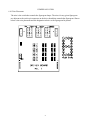
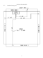
1
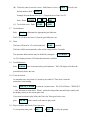
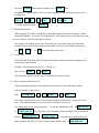
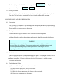
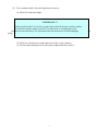
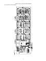
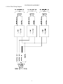
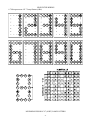
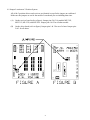
OPERATING INSTRUCTIONS AND SERVICE MANUAL
HOCKEY SCOREBOARD
MODEL MP-3589 WITH MP-3000 Control
EFFECTIVE S.N.18,725, JANUARY, 2006
TABLE OF CONTENTS
1.
General Information
1.1 Description
1.2 Identification
1.3 Damage
1.4 Damage Claim procedure
2.
Installation
2.1 General Information
2.2 Inspection
2.3 Pre-Test
2.4 Data Cable Installation
2.5 Electrical Connection
3.
Control Console Operation
3.1 Scoreboard Power
3.2 Control Console Display
3.3 Control Console Power
3.4 To Use Scoreboard
3.5 Time Control
3.6 Team Scores
3.7 Goal Indicator
3.8 Horn Operation
3.9 Period Indicators
3.10 Time-Out Period
3.11 Player Number & Penalty Time
4.
Maintenance And Troubleshooting
4.1 Introduction
4.2 Test Equipment
4.3 Troubleshooting
4.4 Troubleshooting Guide
5.
Replacement Parts List
5.1 Scoreboard Display Parts (B-7644)
5.2 Controller Assembly Parts
6.
Diagrams
6.1 Keyboard Insert (Slipsheet)
6.2 Scoreboard System Layout
6.3 Single Wall Junction Box Wiring
6.4 Dual Wall Junction Box Wiring
6.5 Controller Plate Wiring and Layout (D-13202)
6.6 Line Filter Wiring
6.7 Microprocessor 4x7 Lamp Pattern (8 Bit)
6.8 Figuregram Wiring Diagram
6.9 Jumper Location on Three Position System
6.10 Triac Placement Diagram
6.11 Installation Drawings
2
1. GENERAL INFORMATION
1.1
DESCRIPTION
Your All-American scoreboard has been carefully inspected and tested before leaving the
factory. It is possible, however, that components may be loosened or forced out of adjustment
in transit. If this occurs, follow the troubleshooting guide (section 4). If equipment then fails to
operate, contact immediately:
ALL-AMERICAN Service Department
EVERBRITE LLC
P.O. Box 100
Pardeeville, WI 53954
Telephone: (608) 429-2121
Toll Free: 800-356-8146
Parts being returned for repair are to be sent to:
ALL-AMERICAN Service Department
EVERBRITE LLC
401 S. Main Street
Pardeeville, WI 53954
NOTE
If you need to send parts in for repair, please call the ALL AMERICAN
service department for a returned goods authorization (RGA) number.
1.2
Identification
ALL-AMERICAN uses a serial number for scoreboard identification. The serial number tags
are located on the back of the control console and the lower right hand corner on the face of the
scoreboard display. When contacting the factory for assistance it is important that the model
number and serial number are known.
1.3
Damage
Upon receipt, check for visible damage. If this occurs, or if damage is found after shipment has
been accepted, follow the damage claim procedure.
1.4
Damage Claim Procedure
An instruction sheet is enclosed advising the consignee in case of damage in transit.
If damage is noted at the time of delivery, consignee must obtain an 'Inspection of Bad Order'
from the delivering carrier. In order to process your claim, this must be properly filled out with
a complete statement of all damage and it must be signed by the carrier.
3
If damage is discovered after delivery, you should call the delivery company. Have them make
out a Concealed Damage Report. Fifteen days after delivery are allowed, so this should be done
promptly or it is impossible to process this claim.
Advise EVERBRITE corporation of necessary replacement parts, or repairs. Consignee will be
invoiced and then should file a claim with the carrier to recover charges. To file your claim
follow this procedure:
(A) Cost of replacement parts, or repair charges, are invoiced to the carrier by the consignee.
(B) The following documents, properly filled out, plus invoice, are forwarded to the trucking
company in support of your claim:
(a)
(b)
(c)
(d)
Original bill of lading
Original paid freight bill
Certified copy of original invoice
Standard form for presentation of loss and damage claim
2. INSTALLATION
2.1
General Information
Shipping papers accompany each scoreboard. Check carefully to see that you receive the
following:
4 ea Hockey Displays
1 ea Control Console
1 ea Service Manual
1 ea Mounting Hardware Package
1 ea Wall Junction Box
1 ea Trumpet Horn
? ft Control Cable (if ordered)
IMPORTANT!
The MP-41 cable supplied by ALL AMERICAN SCOREBOARDS for use on the
Microprocessor based scoreboards is specifically designed for this system. Use of
a substitute cable may void the warranty on the scoreboard!
2.2
Inspection
Inspect each unit and tighten all screws, lamps, and fittings that may have loosened
in shipment.
4
NOTE
A small length of rubber hose may be used as a lamp extractor. Simply
taper the inside of the hose with a sharp knife to fit the lamp.
2.3
Pre-Test
Before installing the scoreboard, pre-test all functions.
2.4
Data Cable Installation
The MP-41 data cable carries only low voltage signals and therefore can be installed with or
without conduit. consult section 6 for junction box and scoreboard wiring.
2.5
Electrical connections
This scoreboard requires a 120/208 V. 60 HZ 3 Phase 4 wire with ground 60 AMP service
for the exclusive use of the scoreboard.
NOTE
To protect the MP-3000 control from damage, it is advisable that you disconnect the
control and store in a dry secure area when not in use.
NOTE
This equipment is UL and NRTL approved and complies with the requirements in part
15 of the FCC rules for a class A computing device. Operation of this equipment in a
residential area may cause unacceptable interference to radio and television reception,
requiring the operator to take whatever steps are necessary to correct the interference.
3. CONTROL CONSOLE OPERATION
3.1
Scoreboard Power
Turn on the branch circuits to the scoreboard. The Home and Guest scores will show "0" .
3.2
Console Display
3.3
The 2 line by 20 character Liquid Crystal Display module displays the scoreboard information
entered from the keyboard. The following information is displayed continuously: Time, Home
and Guest scores, Period, Auto Horn Enable, and Penalty Enable.
Console Power
5
Plug the control console cable into the wall junction box.
Push
ON/OFF
once to turn the console on.
Push
ON/OFF
a second time to shut the console off.
When first turned on; the console display should show as follows.
SCOREBOARD CONTROL
1991 VERSION 3.3
3.4
To Use Scoreboard For Hockey
Enter the two digit code (40) shown in the lower right corner of the keyboard as in the following
example:
Push
CODE
4
0
ENTER .
When the proper code has been entered, the timer will show ":00" and the console display will
show as follows.
0
0H
3.5
:00
0
0
Time Setting and Control
To set an 8 minute period, Push:
SET
8
0
0
ENTER
.
Any time up to 99:59 may be preset in a similar manner.
The
UP/DN key determines the timer mode. When in the UP mode an arrow up symbol
is displayed next to the time on the LCD display. If in the DOWN mode there is no arrow
displayed.
Switching the time toggle switch to the IN and OUT position, starts and stops the timer.
Push
3.6
RESET to return the timer to the previously set value.
Team Scores
The Home and Guest Scores can be changed in three different ways.
(A) To add 1 to the existing score: Push
+1 .
6
(B) To directly enter or correct a score: Push Home or Guest SCORE followed by the
desired number, then
ENTER .
Example: Present Home Score is 15. Change the score from 15 to 23.
Push: Home SCORE
(C) To clear the score: Push
3.7
3
ENTER .
SCORE
CLEAR .
2
Goal Indicator
Push
GOAL to illuminate the appropriate goal indicator.
The LCD will show the letter G when the goal indicator is on.
3.8
Horn
The horn will blow for 1/2 second each time
HORN is pressed.
The horn will blow automatically at the end of each period for 2 seconds.
The automatic horn function may be disabled by using the
AUTO HORN key.
An 'H' is displayed on the LCD when this function is enabled.
3.9
Period Indicators
Push
PERIOD once to increment the period indicator. The LCD display will show the
period directly below the time.
3.10 Time out Period
An automatic time out period of 1 minute is provided for "Time Outs" when the
main timer is not running.
Push:
TIME OUT TIMER to start the 1 minute timer. The LCD will show "TIME OUT
= 1:00" and start to count down. When 1 minute has elapsed the internal beeper sounds, and
the display returns to the current game time.
If you want to return to play before the Time Out Timer gets back to zero,
push:
CLEAR and the console will return to play mode.
3.11 Player Number and Penalty Time Operation
To set a penalty time push:
PEN 1 or
PEN 2 followed by the penalty
7
time, then ENTER ,then the player number and
ENTER again.
EXAMPLE: If Player number 12 has a 3 minute penalty, and this is the first penalty, key in
the following.
PEN 1
3
0
0
ENTER
To enable the timers, push:
1
ENTER .
2
PEN ON .
3.12 Basketball Operation
When using the MP-3589X scoreboard for basketball, replace the Hockey slipsheet with the
Basketball slipsheet, The code is 58 for Basketball. All keyboard entries are made in the same
way as for hockey, with the following exceptions:
The console LCD display shows; time, home and guest score, home and guest team fouls,
period, ball possession, bonus, and auto horn enable, and 1/10 second enable continuously.
The +1 , +2 , and
+3 keys now control the team scores.
3.13 Team Fouls
The Home and Guest team fouls are entered in the same manner as the home and guest team
scoring direct entry method.
Example: Present guest team foul is 3. Change to 4.
Key in Guest
FOUL
ENTER .
4
The scoreboard display will now show 4 team fouls for the guest team.
3.14 Player Number and Player Fouls
The player number and player fouls information is entered as in the following example:
If player number 25 gets a foul;
Push
PLAYER NO.
2
5
ENTER
1
ENTER .
The control console memory will store the player numbers and fouls for 15 players for each
team. This information may be viewed on the LCD display at any time.
This information is now stored in memory. To view the information, push
or
GUEST STATS
Push the
HOME STATS
key. The first 8 player numbers entered, and their fouls are displayed.
HOME STATS
or
GUEST STATS key a second time to display the next 7
player numbers and fouls. To return to normal game display, push
8
GAME DISPLAY .
To clear a player number/foul from memory: push,
you want to clear, then
ENTER
PLAYER NO. followed by the number
CLEAR .
3.15 Boxing Operation
When using the scoreboard for Boxing, replace the console slipsheet with the boxing slipsheet.
The code is 61 for boxing. Operation of all keys is similar to basketball operation.
4. MAINTENANCE AND TROUBLESHOOTING
4.1
Introduction
This section gives maintenance and troubleshooting information. Included are troubleshooting
guides for typical scoreboard malfunctions. If the cause of a problem cannot be determined,
please contact the customer service department.
4.2
Test Equipment
A simple analog or digital voltmeter will be sufficient for all user repairable
problems. Printed circuit boards requiring troubleshooting should be returned to the factory.
WARNING
120 VAC wires are exposed whenever the cover over the controller assembly is
removed from the scoreboard. Use extreme caution during troubleshooting or repair.
To avoid possible damage always remove power before removing the cover or
replacing assemblies.
4.3
Troubleshooting
Whenever possible, follow the troubleshooting guides prior to contacting the customer service
department. If a problem not described in the guides exists, contact the customer service
department immediately. Refer to the diagrams provided for assistance in troubleshooting
scoreboard malfunctions.
4.4
Troubleshooting Guides
(A) Scoreboard doesn't light and console doesn't work
(a)
(b)
(c)
(d)
Check that the main power switch is turned on.
Replace any defective or blown fuses.
Check the power connections and voltages at the scoreboard.
Contact the customer service department.
9
(B) Scoreboard digits don't light, but the console works
(a)
(b)
(c)
(d)
With the main power switch "off"; remove the cover over the controller assembly.
Check all connections.
Turn the main power on.
If the scoreboard still doesn't light, check the transformer voltage going to the receiver
PCB (printed circuit board) assembly (blue wires) using a voltmeter set on the 12 VAC
or higher scale.
If the voltage is less than 8 VAC contact the customer service department.
If the voltage is between 8-12 VAC see the replacement parts list for a receiver PCB
assembly, and contact the customer service department.
(C) The scoreboard digits light but the console doesn't work
(a) Check for continuity between the scoreboard and the junction box.
(b) If an open circuit is found, the problem is either the cable or a cable connection.
(c) If the continuity test checks good, check the voltage between the green wire and the white
wire in the junction box, using a voltmeter set on the 12 VAC or higher scale.
If the voltage is 0 VAC see the controller parts list for a transformer assembly.
If the voltage is less than 8 VAC consult the controller wiring diagram for instructions
on long cable compensation.
If the voltage is between 8 VAC and 12 VAC contact the customer service department.
(D) The scoreboard digits light, the console works, but there is no control of the scoreboard.
(a) Check the voltage between the black and red wires in the junction box with a voltmeter
set on the 3 VDC or higher scale. The voltage should read somewhere between 2-3 VDC
when the console is working properly.
(b) If the voltage is 0 VDC contact the customer service department for assistance.
(c) If the voltage is correct, (2-3 VDC) check that this reading also appears at the scoreboard.
(d) If the correct voltage also appears at the scoreboard, see the replacement parts list for a
receiver PCB assembly.
(E)
The scoreboard works, but some lights stay on all the time
(a) With the main power "OFF", switch the plug from the bad digit with the plug for a
known good digit.
EXAMPLE: Plug "C" into "D" and "D" into "C" locations.
(b) Turn the power back on. If the same lamps remain lit all the time, the problem is a
shorted lamp socket. If the lamps on a different digit now stay lit all the time, the
problem is on the driver PCB assembly. See the replacement parts list for the proper
replacement part.
10
(F)
The scoreboard works, but some lights do not come on.
(a) Check for burned out lamps.
IMPORTANT !!!
In this scoreboard the 120 volt line is on the lamp socket all the time, and the common
is switched to turn the lamps on and off. For this reason, to avoid damage to the
equipment or personal injury, it is important to turn the main power off when changing
lamps.
(b) Check for a broken wire or bad connection on the 12 pin connector.
(c) See the replacement parts list for the proper replacement driver board.
11
the
5. REPLACEMENT PARTS LIST
5.1 Scoreboard Display Parts
figure 1
DISPLAY ASSEMBLY
12
REPLACEMENT PARTS LIST (MP-3589X)
fig.& MFG PART
index NUMBER
11-1
1-2
1-3
1-4
1-5
1-6
1-7
1-8
1-9
1-10
1-11
1-12
1-13
1-14
1-15
REF
DES
DESCRIPTION
180163X
850000
850001
850002
850024
151362
Display Assembly
Lamp, 7C7/125V Red
Lamp, 7C7/125V White
Lamp, 7C7/125V Amber
Lamp, 25W/130V Red
Controller Assembly
*****SEE FIGURE 2*****
119337
Line Filter, Mallory
150036
Placard, Home
150037
Placard, Guest
150038
Placard, Goal
150393
Placard, Player
150075
Placard, Penalty
850029
Lamp, 25W/130V IF
700102
Resistor, 2 OHM 10 WATT
EL055800
Terminal Block, 3C
121880
Fuse, 15A 250V 1/4 X 1 1/4"
SU4450
HB005500
HB002300
SW005100
702785
EL053000
HB002400
WH009100
122763
Control Console
Slipsheet Pair
Transmitter PCB Assembly
Toggle Switch,
Connector, 5 Pin Male Cable
LCD Display, 2 Line 20 Character
Keyboard Assembly,
Ribbon Cable Assembly, 14C 8"
Enclosure,
151204
702786
150500
Wall Junction Box, Single
Connector, 5 Pin Female
Cable, MP-41 Control
150205
700618
Wall Junction Box, Dual
Diode, 1N457A
A2
VENDOR
PART #
180163
7C7/R
7C7/W
7C7/A
25A19 RED
151362
20VB1
150036
150037
150038
150393
150075
25A19 IF
HLM-10-10Z
B-03 EAGLE
F1-F10 ABC-15
A1
S1
P1
SU4450
HB005500
HB002300
SW005100
RM12BPG5P
HB002400
WH009100
J1-J3
151204
RM12BRD5S
8723
150205
D1/D2
13
5.2 Scoreboard Controller Assembly Parts
figure 2
CONTROLLER ASSEMBLY
REPLACEMENT PARTS LIST (MP-3589 Controller Assembly)
fig.& MFG PART
index NUMBER
DESCRIPTION
REF
DES
VENDOR
PART #
2-
151362
Controller Assembly
A2
151362
2-1
2-2
2-2A
2-3
2-4
2-5
2-6
119323
118922
930674
701137
703719
700520
705723
Receiver PCB Assembly
Driver PCB Assy, 3 Position #1-#12
Cable Assy, 3" Ribbon W/ 7C Fem.
Terminal Block, 7C
Transformer Assy, 8V/18V
Varistor,
Spacer, P.C. Board
A3
A4-15
119323
118922
CE100F22-7
670-7
CS-697
ERZ-C20DK201U
LCBS-6-01
14
T1/T2
6. DIAGRAMS
6.1 Control Console Keyboard and Slipsheet Layout
HOCKEY
BASKETBALL
BOXING
15
CONSOLE KEYBOARD
6.2 Scoreboard System Layout
16
SYSTEM LAYOUT
6.3 Single Wall Junction Box Wiring
17
SINGLE WALL JUNCTION BOX WIRING
6.5 Controller Assembly Wiring
18
CONTROLLER ASSEMBLY
6.6 Line Filter Wiring Diagram
19
LINE FILTER WIRING
6.7 Microprocessor 4 X 7 Lamp Pattern (8 Bit)
MICROPROCESSOR 4 X 7 (8 BIT) LAMP PATTERN
20
6.8 Figuregram Wiring
8 BIT FIGUREGRAM WIRING
21
6.9 Jumper Location on 3 Position System
All of the 3 position drivers and receivers are identical except for the jumper on each board.
Make sure the jumpers are set for the model of scoreboard you are installing them into.
(A)
On the receiver board (refer to figure); Jumper pins 2 & 3 for models MP-3385,
MP-3312, MP-3529, and MP-3549. Jumper pins 1 & 2 for all other models.
(B)
On the driver board (refer to figure); Jumper pins 1 & 2 for use of a horn. Jumper pins
2 & 3 for all others.
22
JUMPER LOCATION
6.10 Triac Placement
The triac is the switch that controls the figuregram lamps. The triacs for any given figuregram
are adjacent to the twelve pin connector on the driver board that controls that figuregram. Shown
below is the triac placement and bit designation relative to the figuregram bit pattern.
23
MP TRIAC PLACEMEN
6.11
Installation Drawing
24
6.12
INSTALLATION DRAWING
Installation Drawing (cont.)
25
INSTALLATION DRAWING
26