1
Service Manual
FILE No.
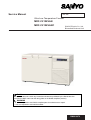
Ultra-Low Temperature Freezer
MDF-C2156VAN
MDF-C2156VANC
SANYO Electric Co., Ltd.
Biomedical Business Unit
RoHS
This product does not contain any hazardous substances prohibited by the RoHS Directive.
(You will find ‘RSF’ mark near the rating plate on the RoHS compliant product.)
WARNING
* You are requested to use RoHS compliant parts for maintenance or repair.
* You are requested to use lead-free solder.
SM9910079
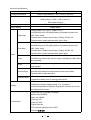
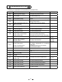
Effective models
This service manual is effective following models.
Model name
MDF-C2156VAN
MDF-C2156VANC
Product code
823 189 82
823 189 83
823 189 84
823 189 87
823 189 86
Voltage and Frequency
220V
50Hz
220V
60Hz
230/240V
50Hz
220V
60Hz
220V
60Hz
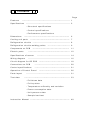
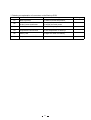
Contents
㩷
Page
Features
---------------------------------------------------
Specifications
---------------------------------------------
1
2
- Structural specifications
- Control specifications
- Performance specifications
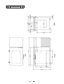
Dimensions
---------------------------------------------------------
Cooling unit parts
-------------------------------------------------
Refrigeration circuits
---------------------------------------
Refrigeration circuits welding points
Components on PCB
Electric parts
7
8
9
----------------------------------------------
11
----------------------------------------------------
12
Specifications of sensor
Wiring diagram
--------------------------
6
----------------------------------
14
------------------------------------------
16
Circuit diagram for CR PCB
------------------------------------
18
Connections on PCB
-------------------------------------
20
Control specifications
---------------------------------------
21
Operation of Control Panel
Parts layout
Test data
------------------------------------
26
---------------------------------------------
31
---------------------------------------------------
33
- Pull-down data
- Pull-up data
- Temperature uniformity and variation
- Power consumption data
- Unit pressure data
- Sample load test
Instruction Manual
㩷
-------------------------------------------------
40
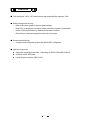
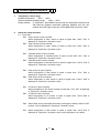
Features
䂓㩷 The chest type -150㷄 VIP series freezer has large effective capacity, 231L.
䂓㩷 Safety storage and security
-
New double door gasket to prevent heat leakage.
-
New VIP+ is adopted for insulation makes reduction of power consumption.
-
Notice of failure prediction by additional new status function.
-
Recording of chamber temperature and outer door open.
䂓㩷 Environmental friendly
-
2-stage mixed refrigerant system with NON-HCFC refrigerant.
䂓㩷 Optional component
zAutomatic temperature recorder + Mounting kit: MTR-155H+MDF-S30150
zInterface board: MTR-480
zLiquid N2 gas container: MDF-135N
1
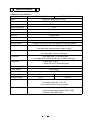
Specifications
㩷
ŶStructural specifications
Item
MDF-C2156VAN
MDF-C2156VANC
Name
Ultra-Low Temperature Freezer
External dimensions
W1730 × D765 × H1010 (mm)
Internal dimensions
W760 × D495 × H615 (mm)
Effective capacity
231 L
Exterior
Painted steel
Interior
Aluminum plate
Outer lid
Painted steel
Insulation
Vacuum insulation panel + Rigid polyurethane foamed-in place
Access port
Cooling circuit
Compressor
㱢40mm, 1 place in the side table
2-stage cooling circuit and Low stage Auto cascade system
High stage side; Hermetic type, Output; 1100W
Low stage side; Hermetic type, Output; 1100W
Evaporator
High stage side; Cascade condenser type
Low stage side; Tube on sheet type
Condenser
High stage side; Fin and tube type
Low stage side; Shell and tube type, and Wire tube type
Refrigerant
H stage side; R-407D
L stage side; HFC mixed refrigerant
Refrigerating oil
Ze-NIUS32SA
Power supply
Local voltage
Battery
Weight
Voltage booster
Accessories
Lead storage battery, 6VDC, 7.2Ah x 4pcs, Auto-recharge
318 kg
325kg
None
Built-in
1 set of key for outer door latch, 1 set of key for panel door,
6 recording chart rolls, 1 dry cell
1 set connect tube for back-up system
Optional component
Automatic temperature recorder + Mounting kit (MTR-155H+MDF-S30150)
Liquid nitrogen gas container (MDF-135N)
Interface board (MTR-480)
㩷
㩷
㩷
㩷
㩷
㩷
㩷
2
ŶControl specifications
Item
Cooling performance
MDF-C2156VAN
MDF-C2156VANC
Center of the chamber; -150㷄䋨AT30㷄, No load䋩
Temp. controller
Micro-processor control system
Setting range; -125㷄䌾-155㷄䋨Unit;1㷄䋩
Non-volatile memory
Temp. sensor
Platinum resistance; Pt.1000ȍ
Temp. display
Digital display
Setting range: +5㷄~+20㷄 (Initial; +10㷄)
ALARM lamp and LCD display flashes, intermittent buzzer tone
High temp.
with 15min. delay
Remote alarm contact: Normal Open, Rating; DC30V, 2A
Remote alarm contact activates with 15min delay
Setting range: -5㷄~-20㷄 (Initial; -10㷄)
ALARM lamp and LCD display flashes, intermittent buzzer tone
Low temp.
with 15min. delay
Remote alarm contact: Normal Open, Rating; DC30V, 2A
Remote alarm contact activates with 15min delay
Alarm
When outer door is open, indication of ‘Door Open’ is shown.
Door
ALARM lamp blinks and buzzer beeps intermittently after delay
time is passed.
Filter
ALARM lamp flashes, message indication and intermittent buzzer
tone emitted
When the power to the unit is not connected or power failure,
Power failure
ALARM lamp flashes and intermittent buzzer tone emitted
Remote alarm contact activates.
Remote alarm
3P remote alarm terminal: DC30V, 2A, NC-COM, NO-COM
Temperature alarm turns on during power failure.
LCD panel
Display
Temperature display; Digital display (1㷄 increment)
Internal temperature is displayed by graphics, 24hours record can
be displayed per screen.
Lamp: BATTERY, ALARM, STANDBY
Buzzer key: BUZZER
Menu key: MENU
Control panel
Clear key: CE
Entry key: ENT
Figure input key
LCD contrast adjusting knob: CONT
Shift key:
3
㩷
Item
MDF-C2156VAN
MDF-C2156VANC
When ambient temperature is higher than approx. 35㷄 or lower
Status monitor function
than approx. 0㷄, ‘Ambient temp is abnormal ‘ is displayed on LCD.
When power supply voltage is lower than approx.170V, ‘The power
supply is abnormal’ is displayed on LCD.
zRecordable for approx. 4weeks in 12min. intervals.
zDoor delay time (more than 2min.) is recordable.
Data log function
zTemperature for cascade sensor, filter sensor and AT sensor
are recordable.
zLog
data
is
transmittable
to
PC
with
interface,
MTR-480.(Option)
In the event of any failure among temp. sensor, filter sensor and
cascade sensor;
Self diagnosis function
zError code and message are emitted.
zALARM lamp flashed, remote alarm contact turns over and
intermittent buzzer emit.
Key lock function
Key lock ‘0’: Key lock is released.
Key lock ‘1’: Key locks
When the temperature in cascade sensor is -34 㷄 or lower,
compressor (L) turns on.
L stage
When the temperature in cascade sensor is -12 㷄 or higher,
compressor (L) turns off.
Compressor
Overload relay and High pressure switch (L) are controlled.
protection
When the temperature in filter sensor is +60 㷄
H stage
or higher,
compressor (H) turns off.
When the temperature in filter sensor is 10㷄 lower than ambient
temperature, compressor (H) turns on.
zAutomatic liquid N2 injection device
zTemp. setting range;
zIndication: BACK-UP (Green)
Back-up systems
zBack-up test switch; 8R2021
zPower switch; Locker switch
zBack-up systems can be available for 48 hours by full charged
lead storage battery.
㩷
㩷
㩷
㩷
㩷
㩷
4
㩷
ŶPerformance specifications
Cooling performance
Center of the chamber: -150㷄䋨AT30㷄, no load䋩
Temp. control range
-125㷄䌾-150㷄䋨AT30㷄, no load䋩
Rated power consumption
Noise level
220VAC, 50Hz
220VAC, 60Hz
230VAC, 50Hz
240VAC, 50Hz
1550W
1700W
1550W
1600W
51 dB (A) (background noise; 20dB)
Maximum pressure
Usable conditions
3085 kPa
AT:5㷄䌾30㷄, less than 80䋦RH
Note: Specifications will be subject to change without notice.
5
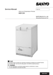
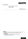
Dimensions
6
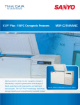
Cooling unit parts
<MDF-C2156VAN/VANC>
Specifications
Item
H side
Compressor
220V, 60Hz
220V, 50Hz
230/240V, 50Hz
Refrigerant oil
Cooling system
L side
Type: KS370J1NS-7A
Compressor code: 7FB-0-M101-001-06
Type: KS370J1NS-4A
Compressor code: 7FB-0-M101-001-04
Type: KS370J1NS-4A1 Compressor code: 7FB-0-M101-001-05
Ze-NIUS32SA
Ze-NIUS32SA
Charged q’ty: 850cc
Charged q’ty: 850cc
Forced air cooling(partially)
Forced air cooling(partially)
Oil cooler
Oil cooler
Condenser
Type
Condenser
Pre-condenser
Frame pipe
Evaporator
Type
Capillary tube
Resistance
PSI・kg/cm2
Length (mm)
Outer diameter (mm)
Inner diameter (mm)
Refrigerant
Fin and tube
12 columns x 4 lines P6.35mm
Fin 88pcs.
W 350mm
φ6.35mm
Coil pipe
φ6.35mm x (t)0.7
ʊ
ʊ
Shell tank φ80mm
(upper)
2
Tube on sheet
(Middle) (Lower)
2
2
(Ex)
2
56 PSI/G
9.9kg/cm
11.0kg/cm
3.7kg/cm
1.9kg/cm
1300
φ2.4
φ1.2
3000
8000
3000
500
R-407D Charged q’ty: 432+/-10g
MU-N721 (HFC refrigerant)
Charged q’ty: 880g
n-Pentane
n-Pentane
Charged q’ty: 46cc (28g)
Charged q’ty: 17cc (10g)
4A-XH-9
Charged q’ty: 18g
4A-XH-6
Charged q’ty: 58g
φ230 mm、4 blades
Material: ABS
Oil additive
Dryer
Condensing fan
Condensing fan
motor
Oil separator
Type: SE4-E11L5P
ʊ
SPK-0S02S3
<Compressor terminals layout>
C
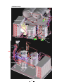
Cascade condenser
R
S
7
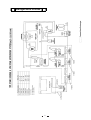
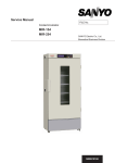
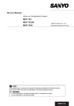
Refrigeration circuits
8
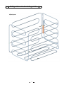
Refrigeration circuit welding points
<Pipe layout>
䌅䌁㩷 䌅䌇㩷
䌅䌂㩷
䌅䌃㩷
䌅䌄㩷
䌅䌆㩷
9
<Unit base Ass’y>
Pressure SW
Ex. tank (L)
䌐䌉㩷
䌅䌘䌂
䌅䌘䌁
䌅䌘䌚㩷
䌅䌘䌙㩷
䌅䌘䌗
Condenser Ass’y䌌䌄䌅㩷
䌌䌄䌃
䌅䌘䌃
䌅䌘䌄
䌅䌘䌘㩷
䌅䌘䌖
䌌䌄䌇㩷
䌌䌄䌆㩷
䌐䌏㩷
䌌䌄䌈㩷
䌌䌄䌊㩷
䌅䌘䌅㩷
䌅䌘䌕
䌅䌘䌔㩷
䌈䌄䌋
䌅䌘䌒 䌅䌘䌓
䌅䌘䌏
䌅䌘䌐
䌈䌄䌆㩷
䌈䌃䌂㩷
䌈䌃䌁㩷
Compressor (L)
䌈䌄䌇㩷
䌈䌄䌌㩷
䌅䌃䌏
䌅䌘䌑
䌅䌃䌉㩷
䌅䌘䌎
䌅䌘䌍
䌈䌄䌂
䌌䌄䌂㩷
䌌䌃䌆㩷
䌈䌃䌃㩷
䌈䌄䌁
䌌䌄䌁 䌌䌏䌁 䌌䌏䌂 䌌䌃䌇
䌈䌏䌏
䌈䌏䌉㩷
䌌䌏䌉㩷 䌌䌏䌏
䌈䌃䌇
䌌䌃䌈 䌈䌃䌈
䌈䌏䌁㩷
䌈䌏䌂㩷
䌈䌆䌉㩷
䌈䌆䌏㩷
䌌䌄䌄㩷
䌌䌄䌐㩷
Compressor(H)
䌈䌓䌃㩷
䌌䌄䌍㩷 䌌䌃䌅
䌌䌓䌄 䌌䌓䌃
䌌䌄䌌㩷
䌌䌄䌎㩷 䌌䌃䌄
䌅䌘䌌㩷
䌈䌓䌁
䌌䌓䌅
䌈䌓䌂㩷
䌏䌒㩷
䌏䌉㩷
䌌䌓䌁 䌌䌓䌂
䌏䌏㩷
䌌䌄䌋㩷
䌈䌓䌄㩷
䌌䌓䌆㩷
Capillary (H)
䌈䌄䌏㩷
䌈䌄䌉㩷
䌈䌄䌃
䌌䌃䌂㩷
䌌䌃䌁㩷
Oil separator
䌈䌄䌅
䌈䌃䌏
䌅䌘䌁㩷
10
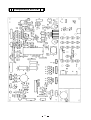
Components on PCB
11
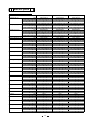
Electric parts
MDF-C2156VAN/2156VANC
Compressor (H), (L)
Starting relay (H), (L)
Overload relay (H), (L)
Starting capacitor (H), (L)
Running capacitor (H), (L)
Condensing fan motor
Cap.tube heater
Temp. control relay (H)
Heater relay
Temp. control relay (L)
Switching power supply
Transformer
Pressure switch
Door switch
Temp. sensor
Transformer
Battery switch
Battery
Cascade sensor
Filter sensor
AT sensor
Remote switch
Solenoid valve
Back up switch
Test switch
220V, 60Hz
Type
KS370J1NS-7A
Parts code
7FB 0 M101 001 06
Rated voltage
220V, 60Hz
Winding resistance䋨C-S)
1.64㱅
Winding resistance䋨C-R)
3.35ȍ
Type
AMVL-300A
Pick-up voltage
215~247VAC
Drop-out voltage
69~132VAC
Parts code
626 100 1503
Type
MRA999549201
Action to temp. (no current) ON:69㫧10㷄 OFF:135㫧10㷄
Action to current (AT25㷄)
29.5A
Operation time
6~16 sec.
Parts code
624 226 3173
Type
160UF, 250V
Type
25UF, 400VAC
Type
SE4-E11L5P
Rated voltage
220-240V
Parts code
624 224 0167
Rated voltage
100V, 15.7W
Resistance䋨25㷄)
638㱅
Parts code
624 030 2492
Type
G4F-11123T
Rated voltage
20A, 12VDC
Parts code
624 173 2397
Type
G2R-1A-T
Rated voltage
12V, 1-A, 250V
Parts code
624 188 9299
Type
G4F-11123T
Rated voltage
20A, 12VDC
Parts code
624 173 2397
Type
ZWS15-12/J
Rated voltage
15W, 12V
Parts code
624 227 1291
Type
ATR-C50
Rated voltage
200-240V
Parts code
624 006 0408
Type
SNS-C135Q002
Rated voltage OFF:2.75MPA ON:0.78MPA
Parts code
624 227 0959
Type
SS160-A15
Rated voltage
28V, 50MA
Parts code
624 197 1925
Type
PT-1000㱅
Type
S41-RN98PV
Rated voltage
P:100V, 9V, 0.46A
Parts code
624 227 0836
Type
SLE6A2-5
Rated voltage
4A, 250VAC
Parts code
624 213 1472
Type
LC-P067R2J
Rated voltage
6V, 7.2AH
Parts code
624 227 0843
Type
502AT
Rated voltage
5K㱅, 25㷄
Type
502AT
Rated voltage
5K㱅, 25㷄
Type
502AT
Rated voltage
5K㱅, 25㷄
Type
HLS208N
Rated voltage
250VAC, 6A
Parts code
624 169 9690
Type
X8263205LT
Rated voltage
24VDC
Parts code
624 226 8215
Type
HLS208N
Rated voltage
250VAC, 6A
Parts code
624 169 9690
Type
8R2021
Rated voltage
3A, 125VAC
Parts code
624 194 3984
12
220V, 50Hz
230/240V, 50Hz
KS370J1NS-4A
7FB 0 M101 001 04
220/230V, 50Hz
2.53ȍ
4.8ȍ
AMVL-300A
185~217VAC
60~120VAC
626 100 1503
MRA999539201
ON:69㫧10㷄 OFF:135㫧10㷄
22.5A
6~16 sec.
624 226 3166
100UF, 250V
25UF, 400VAC
SE4-E11L5P
220-240V
624 224 0167
100V, 15.7W
638㱅
624 030 2492
G4F-11123T
20A, 12VDC
624 173 2397
G2R-1A-T
12V, 1-A, 250V
624 188 9299
G4F-11123T
20A, 12VDC
624 173 2397
ZWS15-12/J
15W, 12V
624 227 1291
ATR-C50
200-240V
624 006 0408
SNS-C135Q002
OFF:2.75MPA ON:0.78MPA
624 227 0959
SS160-A15
28V, 50MA
624 197 1925
PT-1000㱅
S41-RN98PV
P:100V, 9V, 0.46A
624 227 0836
SLE6A2-5
4A, 250VAC
624 213 1472
LC-P067R2J
6V, 7.2AH
624 227 0843
502AT
5K㱅, 25㷄
502AT
5K㱅, 25㷄
502AT
5K㱅, 25㷄
HLS208N
250VAC, 6A
624 169 9690
X8263205LT
24VDC
624 226 8215
HLS208N
250VAC, 6A
624 169 9690
8R2021
3A, 125VAC
624 194 3984
KS370J1NS-4A1
7FB 0 M101 001 05
230/240V, 50Hz
2.53ȍ
4.8ȍ
AMVL-300A
185~217VAC
60~120VAC
926 100 1504
MRA999539201
ON:69㫧10㷄 OFF:135㫧10㷄
22.5A
6~16 sec.
924 226 3167
100UF, 250V
25UF, 400VAC
SE4-E11L5P
220-240V
924 224 0168
100V, 15.7W
638㱅
924 030 2493
G4F-11123T
20A, 12VDC
924 173 2398
G2R-1A-T
12V, 1-A, 250V
924 188 9290
G4F-11123T
20A, 12VDC
924 173 2398
ZWS15-12/J
15W, 12V
924 227 1292
ATR-C50
200-240V
924 006 0409
SNS-C135Q002
OFF:2.75MPA ON:0.78MPA
924 227 0950
SS160-A15
28V, 50MA
924 197 1926
PT-1000㱅
S41-RN98PV
P:100V, 9V, 0.46A
924 227 0837
SLE6A2-5
4A, 250VAC
924 213 1473
LC-P067R2J
6V, 7.2AH
924 227 0844
502AT
5K㱅, 25㷄
502AT
5K㱅, 25㷄
502AT
5K㱅, 25㷄
HLS208N
250VAC, 6A
924 169 9691
X8263205LT
24VDC
924 226 8216
HLS208N
250VAC, 6A
924 169 9691
8R2021
3A, 125VAC
924 194 3985
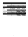
MDF-C2156VAN/2156VANC
Relay
Power transformer
Back up sensor
Breaker switch
Noise filter
Time delay fuse
Breaker switch
(MDF-C2156VANC only)
Power relay
(MDF-C2156VANC only)
Boost relay
(MDF-C2156VANC only)
Power transformer
(MDF-C2156VANC only)
Power transformer
(MDF-C2156VANC only)
Type
Rated voltage
Parts code
Type
Rated voltage
Parts code
Type
Type
Rated voltage
Parts code
Type
Rated voltage
Parts code
Type
Rated voltage
Parts code
Type
Rated voltage
Parts code
Type
Rated voltage
Parts code
Type
Rated voltage
Parts code
Type
Rated voltage
Parts code
Type
Rated voltage
Parts code
220V, 60Hz
220V, 50Hz
230/240V, 50Hz
G4F-1123T
1C, 15A, 24VDC
624 001 4586
ATR-K285T
P:100V, 115V, 230V
624 227 0850
PT-1000ȍ
BAM215171
250V, 15A
624 226 3623
ZAC2220-11
250VAC, 20A
624 204 3294
SD4 UL E39265
250V, 0.5A
423 018 2109
IR11A2E201R
250VAC, 20A
624 225 9589
G7L-1A-TUB
30A, 220V, 24VDC
624 208 1043
G7L-1A-TUB
30A, 220V, 24VDC
624 208 1043
ATR-HJ61TC-1
200, 225, 240V
624 226 7614
ATR-D35003
P:208V, S:230V
624 226 7621
G4F-1123T
1C, 15A, 24VDC
624 001 4586
ATR-K285T
P:100V, 115V, 230V
624 227 0850
PT-1000ȍ
BAM215171
250V, 15A
624 226 3623
ZAC2220-11
250VAC, 20A
624 204 3294
SD4 UL E39265
250V, 0.5A
423 018 2109
G4F-1123T
1C, 15A, 24VDC
924 001 4587
ATR-K285T
P:100V, 115V, 230V
924 227 0851
PT-1000ȍ
BAM215171
250V, 15A
924 226 3624
ZAC2220-11
250VAC, 20A
924 204 3295
SD4 UL E39265
250V, 0.5A
323 018 2102
13
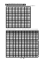
Specification of sensor
1. Following shows temperature and resistance values in thermistor sensor (502AT-1).
㷄
kȍ
㷄
kȍ
㷄
kȍ
㷄
kȍ
䋭50
154.5
䋭36
71.80
䋭22
35.65
0
13.29
䋭49
145.9
䋭35
68.15
䋭21
33.99
5
10.80
䋭48
137.8
䋭34
64.71
䋭20
32.43
10
8.84
䋭47
130.2
䋭33
61.48
䋭19
30.92
15
7.20
䋭46
123.1
䋭32
58.43
䋭18
29.50
20
6.01
䋭45
116.5
䋭31
55.55
䋭17
28.14
25
5.00
䋭44
110.2
䋭30
52.84
䋭16
26.87
30
4.17
䋭43
104.4
䋭29
50.23
䋭15
25.65
35
3.50
䋭42
98.87
䋭28
47.77
䋭14
24.51
40
2.96
䋭41
93.70
䋭27
45.45
䋭13
23.42
45
2.51
䋭40
88.85
䋭26
43.26
䋭12
22.39
50
2.13
䋭39
84.18
䋭25
41.19
䋭11
21.41
55
1.82
䋭38
79.80
䋭24
39.24
䋭10
20.48
60
1.56
䋭37
75.67
䋭23
37.39
䋭5
16.43
65
1.35
2. Following shows temperature㩷 䋨-170㷄䌾0㷄䋩㩷 and resistance values in temp. sensor (Pt1000ȍ).
䋨㷄䋩
0
-1
-2
-3
-4
-5
-6
-7
-8
-9
-170
330.4
326.2
322.1
318.0
313.8
309.7
305.5
301.4
297.3
293.1
-160
371.4
367.3
363.2
359.1
355.0
350.9
346.8
342.7
338.6
334.5
-150
412.2
408.2
404.1
400.0
395.9
391.9
387.8
383.7
379.6
375.5
-140
452.8
448.7
444.7
440.6
436.5
432.5
428.5
424.4
420.4
416.3
-130
493.0
489.0
485.0
481.0
477.0
472.9
468.9
464.9
460.8
456.8
-120
533.1
529.1
525.1
521.1
517.1
513.1
509.1
505.1
501.1
497.1
-110
572.9
569.0
565.0
561.0
557.0
553.0
549.1
545.1
541.1
537.1
-100
612.6
608.6
604.6
600.7
596.7
592.8
588.8
584.8
580.9
576.9
-90
652.0
648.1
644.1
640.2
636.2
632.3
628.4
624.4
620.5
616.5
-80
691.3
687.3
683.4
679.5
675.6
671.6
667.7
663.8
659.9
655.9
-70
730.3
726.4
722.5
718.6
714.7
710.8
706.9
703.0
699.1
695.2
-60
769.3
765.4
761.5
757.6
753.7
749.8
745.9
742.0
738.1
734.2
-50
808.1
804.2
800.3
796.4
792.6
788.7
784.8
780.9
777.0
773.2
-40
846.7
842.8
839.0
835.1
831.3
827.4
823.5
819.7
815.8
811.9
-30
885.2
881.4
877.6
873.7
869.8
866.0
862.1
858.3
854.4
850.6
-20
923.6
919.8
915.9
912.1
908.3
904.4
900.6
896.7
892.9
889.1
-10
961.9
958.0
954.2
950.4
946.6
942.7
938.9
935.1
931.3
927.4
0
1000.0
996.2
992.4
988.6
984.8
980.9
977.1
973.3
969.5
965.7
14
2. Following shows temperature㩷 䋨0㷄䌾100㷄䋩㩷 and resistance values in temp. sensor (Pt1000ȍ).
䋨㷄䋩
0
1
2
3
4
5
6
7
8
9
0
1000.0
1003.8
1007.6
1011.4
1015.2
1019.0
1022.8
1026.6
1030.4
1034.2
10
1038.0
1041.8
1045.6
1049.4
1053.2
1057.0
1060.8
1064.6
1068.4
1072.2
20
1076.0
1079.7
1083.5
1087.3
1091.1
1094.9
1098.7
1102.4
1106.2
1110.0
30
1113.8
1117.5
1121.3
1125.1
1128.8
1132.6
1136.4
1140.1
1143.9
1147.7
40
1151.4
1155.2
1159.0
1162.7
1166.5
1170.2
1174.0
1177.7
1181.5
1185.2
50
1189.0
1192.7
1196.5
1200.2
1204.0
1207.7
1211.5
1215.2
1219.0
1222.7
60
1226.4
1230.2
1233.9
1237.6
1241.4
1245.1
1248.8
1252.6
1256.3
1260.0
70
1263.8
1267.5
1271.2
1274.9
1278.7
1282.4
1286.1
1289.8
1293.5
1297.2
80
1301.0
1304.7
1308.4
1312.1
1315.8
1319.5
1323.2
1326.9
1330.6
1334.3
90
1338.0
1341.7
1345.4
1349.1
1352.8
1356.5
1360.2
1363.9
1367.6
1371.3
100
1375.0
1378.7
1382.4
1386.1
1389.8
1393.4
1397.1
1400.8
1404.5
1408.2
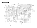
15
Wiring Diagram
<MDF-C2156VAN>
16
<MDF-C2156VANC>
17
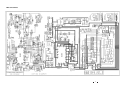
Circuit Diagram
18
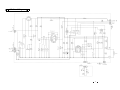
CR Circuit Diagram
19
Connections on PCB
* Following are explanation of connections on the Main PCB.
Connector
Connects to
Usage
CN1
Switching power supply
To supply the power to PCB.
CN2
LCD module
To connect with LCD.
CN3
Control Board (CN5)
#1-#2: Battery switch
CN4
#3-#4: Transformer(100V, 9V)
To connect with LCD contrast adjusting
knob.
To supply the power to Main PCB #1-#2: 24V
during power failure.
To detect abnormal low voltage.
CN5
Main PCB (CN3)
CN6
Main PCB (CN18)
CN7
MTR-480 (Option)
To connect with interface.
CN8
#1-#2: Buzzer PCB
To connect with buzzer.
CN9
#1-#2: Temp. control relay H
#3-#4: Temp. control relay L
#5-#6: Heater relay
To control compressor H.
To control internal temperature.
To supply the power to cap. tube heater.
CN10
#3-#4: Door switch
To control digital lock (Option).
CN11
Remote alarm terminal
Remote switch
To output remote alarm
#1-#2: AT sensor
#3-#4: Filter sensor
CN12
Voltage
#1: 12V
#1: 5V
#1: 12V
#2: 5V
#1: COM
#2: N.C.
#3: N.O.
To detect ambient temperature.
To detect temperature at condenser
outlet pipe.
To detect temperature at cascade.
To control door switch.
CN13
#5-#6: Cascade sensor
#9-#10: Door switch
Unused
CN14
LCD module
CN15
Main PCB (CN8)
CN16
Unused
CN17
#1-#2: Switching power supply
#3-#4: Lock
To supply the power to digital lock.
CN18
Control board (CN6)
To connect with each keys.
CN19
#3-#4: Back up PCB
To connect with back-up system.
CN20
#1-#3: Temp. sensor
To detect internal temperature.
CN21
#3-#4: Analog terminal
To output analog.
To supply the power to back lamp for
LCD.
20
#1: 24V
#3: 24V
* Following are explanation of connectors on the Back-up PCB.
Connector
Connects to
Usage
S1
Back-up sensor
To detect internal temperature.
S2
#1-#2: Solenoid valve
#3-#4: Power transformer
To supply the power to solenoid valve.
To supply the main power
S3
#1-#2: Test switch
To test back-up system.
S4
Temperature control knob
To set temperature for back-up.
S5
Battery LED
To light LED when low battery.
S6
Temperature control dial
21
Voltage
24V
Control specifications
1.
Temperature control range
Settable temperature: -125㷄 ~ -155㷄
Internal temperature display range: -180㷄 ~ +50㷄
Setting method: In ‘TopScreen’, press MENU key and step into temperature setting mode
with Shift key (upward, downward, rightward, leftward), then set your
desired value with Figure Input key. Press MENU/OK to store the value.
2.
Alarm and safety functions
(1) Error code
E01: Temp. sensor is open circuited.
When temperature in temp. sensor is equal or higher than -180㷄, ‘E01’ is
displayed in ‘TopScreen’, the basic screen.
E02: Temp. sensor is short circuited.
When temperature in temp. sensor is equal or lower than +50㷄, ‘E02’ is
displayed in ‘TopScreen’, the basic screen.
E03:
E04:
E05:
E06:
E07:
E08:
Cascade sensor is open circuited.
When temperature in cascade sensor is equal or lower than -70㷄, ‘E03’ is
displayed in ‘TopScreen’, the basic screen.
Cascade sensor is short circuited.
When temperature in cascade sensor is equal or higher than +100㷄, ‘E04’ is
displayed in ‘TopScreen’, the basic screen.
Filter sensor is open circuited.
When temperature in filter sensor is equal or lower than -70㷄, ‘E05’ is
displayed in ‘TopScreen’, the basic screen.
Filter sensor is short circuited.
When temperature in filter sensor is equal or higher than +100㷄, ‘E06’ is
displayed in ‘TopScreen’, the basic screen.
AT sensor is open circuited.
When temperature in AT sensor is equal or lower than -70㷄, ‘E07’ is displayed
in ‘TopScreen’, the basic screen.
AT sensor is short circuited.
When temperature in AT sensor is equal or higher than +100㷄,’E08’ is
displayed in ‘TopScreen’, the basic screen.
E09:
When Alarm test is performed with battery uncharged or battery switch is OFF
position, ‘E09’ is displayed in ‘TopScreen’, the basic screen.
E10:
When temperature in filter sensor is equal or higher than +60㷄,’E10’ is
displayed in ‘TopScreen’, the basic screen, and Compressor H is ceased.
22
(2)
High temp. alarm
When internal temperature is higher than high temperature alarm setting value, alarm
lamp flashes, intermittent buzzer beeps with 15 minutes of delay and remote alarm
activates.
Press BUZZER key to stop buzzer beeping. However, buzzer beeps again after Ring
Back time is passed. Remote alarm is still activated during this period.
High temp. alarm setting range: SV+5㷄 ~ +20㷄 (Initial: +10㷄)
Ring Back time setting range: 1 ~ 99 minutes (Initial: 30 minutes)
* 0 minutes = Alarm does not recover.
* Note) During pull-down, both buzzer and remote alarm don’t activate.
(3)
Low temp. alarm
When internal temperature is lower than low temperature alarm setting value, alarm
lamp flashes, intermittent buzzer beeps with 15 minutes of delay and remote alarm
activates.
Press BUZZER key to stop buzzer beeping, however, buzzer beeps again after Ring
Back time is passed. Remote alarm is still activated during this period.
Low temp. alarm setting range: SV-5㷄 ~ -20㷄 (Initial: -10㷄)
Ring Back time setting range: 1 ~ 99 minutes (Initial: 30 minutes)
* 0 minutes = Alarm does not recover.
* Note) During pull-down, both buzzer and remote alarm don’t activate.
(4)
Door alarm
When door is open, intermittent buzzer beeps and ‘DOOR’ at ‘TopScreen’ flashes.
Shut door or press BUZZER key to stop buzzer beeping. Remote alarm does not
activate during this period.
Door alarm setting range: 1 ~ 15 minutes (Initial: 2 minutes)
(5)
Filter alarm
When temperature in filter sensor is equal or higher than +48.0㷄, intermittent buzzer
beeps and ‘FILTER’ at ‘TopScreen’ flashes. Remote alarm does not activate.
Press BUZZER key to stop buzzer beeping. (Buzzer does not recover automatically)
When temperature in filter sensor is equal or lower than +43.0㷄, buzzer stops beeping
and indication is disappeared.
If you set buzzer does not activate, buzzer does not beep.
(6)
Remote alarm
Remote alarm is output from the terminal.
Contact status ‘Normal’: ‘Open’ between COM. and N.O.
‘Close’ between COM. and N.C.
Contact status ‘Abnormal’: ‘Open’ between COM. and N.C.
‘Close’ between COM. and N.O.
*Note) When remote alarm is OFF position at Default setting screen, remote alarm
does not activate. (Initial: 1 (=ON))
23
3.
Buzzer Auto-recovery (Ring Back function)
You can stop buzzer beeping temporary with BUZZER key pressed. Remote alarm
contact does not activate at the time.
Ring Back setting time: 1 ~ 99 minutes
* 0 minute = Buzzer does not recover if BUZZER key pressed once.
4.
ON/OFF control for Compressor H
Start-up: Compressor H turns on with 2 minutes of delay after the power is supplied.
Compressor H starts with designed delay time after the power failure.
Protection: Compressor H is forcibly turned off when temperature in filter sensor is equal or
higher than +60㷄.
Recovery: Compressor H is turned on when temperature in filter sensor is equal or lower
than AT + 10㷄 and also compressor delay time is passed.
5.
ON/OFF control for Compressor L
ON: When cascade temperature is equal or lower than -34㷄, Compressor L is turned on.
OFF: When cascade temperature is equal or higher than -12㷄, Compressor L is turned off.
Differential: When compressor delay timer is set at ‘0’ and controlled temperature is higher
than SV+0.5㷄, Compressor L is turned on.
When controlled temperature is SV-0.5㷄, Compressor L is turned off.
6.
Monitor of freezer status
(1) Abnormal ambient temperature
When ambient temperature is equal or lower than 0㷄, or equal or higher than +35㷄,
‘Status-1’ is displayed.
(2) Voltage decline
When the voltage decreases in about 170V, ‘Status-2’ is displayed.
When the unit detects above abnormal status, the Status indication flashes on the basic
screen with massage indication.
(3) Compressor running rate
You can see compressor running rate in the indication of MENU/Svc – Status in the
screen of ‘Hardware Status’.
* Running rate of Compressor L
= {Compressor ON time / (Compressor ON time + Compressor OFF time)} x 100 (%)
7.
Control of Cap. tube heater
Cap. tube heater is permitted to turn on once every 18 hours.
Cap. tube heater is forcibly turned on for 8 minutes after compressor L is turned off and
8.
MENU screen
In MENU is displayed on the basic screen, MENU is automatically disappeared if there is not
any key inputs for 1 minute.
In MENU is not displayed on the basic screen, the screen is changed for renewal once every
hours.
24
9.
Operation in power failure
Unit checks power failure by the port for detecting power failure in every 0.42 seconds.
Operation in power failure;
- All ports for controlling compressor, cap. tube heater, LCD back lamp, signal lines and
digital lock turn off and unit operates to the mode in low power consumption.
- LCD is turned off and intermittent buzzer beeps.
- If you press BUZZER key, buzzer stops beeping, LCD back lamp is lit for 5 seconds
and you can check the time when power failure was occurred. However, buzzer beeps
again after buzzer resume time is passed.
- Log data is stored.
10.
Auto Return
Display changes to the basic screen if there are any key inputs for 90 seconds.
11.
Notice of parts replacement
- Battery replacement: When battery accumulating time is over than 2.8 years,
‘Please exchange batteries’ is indicated.
- Fan motor replacement: When fan motor accumulating time is over than 5.6 years,
‘Please exchange fan motor’ is indicated.
12.
Warning message
Y
13.
M
D
H
M
S
High temp. alarm:
‘ High Temp Warning 20XX/XX/XX XX:XX:XX ‘
Low temp. alarm:
‘ Low Temp Warning 20XX/XX/XX XX:XX:XX ‘
Power failure alarm: ‘ Power failure Warning 20XX/XX/XX XX:XX:XX ‘
Filter alarm: ‘ Please check a condenser filter ‘
Setting specifications
Internal temperature
High temp. alarm
Low temp. alarm
Alarm delay time
Compressor L ON/OFF
Cycle of Cap. tube heater ON
Differential of Compressor L
Filter alarm operation
Auto Return
Key lock password
-155㷄~-125㷄
(Initial: -150㷄)
+5㷄~+20㷄
(Initial: +10㷄)
-5㷄~-20㷄
(Initial: -10㷄)
15 min.
ON: -34㷄
OFF: -12㷄
Ring Back
Door delay time
Log record time
Compressor L delay time
Compressor delay time after
power failure
Every 18hrs.
Cap. tube heater ON time
+/- 0.5㷄
Compressor H protection
Message
Buzzer:ON/OFF
(Initial: ON)
90 sec.
Initial: 0000
25
1~99 min.
0: OFF
(Initial: 30 min.)
1~15 min.
(Initial: 2 min.)
2~30 min.
(Initial: 15 min.)
2 min.
2~15 min.
(Initial: 15 min.)
6~15 min.
(Initial: 8 min.)
OFF: +60㷄 up
ON: AT+10㷄
Internal temp. offset
-4.0㷄
Auto MENU OFF
60 sec.
㩷
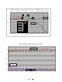
Operation of Control Panel
㩷
Note: For the operations of ‘Basic Screen’, ‘Function’, ‘Key Lock function’, ‘Display of Log’,
‘Various Setting’, ‘Initialization’ ‘Setting of date, time, log interval’ and ‘Key Lock
Password’, please refer to P.15~P.22 in the Instruction Manual.
1䋮Buzzer
・Buzzer for Temperature Alarm (Intermittent tone)
Buzzer beeps intermittently after 15 minutes has passed since the unit was detected High Temp. alarm or
Low Temp. alarm. Press BUZZER key to stop buzzer beeping.
Buzzer beeps again if the unit still keeps alarming condition even after Ring Back time has passed.
zIntermittent buzzer tone and message indication emitted even after Auto Recovery.
zPress BUZZER key to erase message and buzzer tone.
・Buzzer for Door Alarm (Intermittent tone)
Buzzer beeps intermittently after delay time has passed since door was open.
Shut door or press BUZZER key to stop buzzer beeping.
zRemote alarm does not activate.
・Buzzer for Filter Alarm (Intermittent tone)
Buzzer beeps intermittently when temperature in filter sensor is equal or higher than +48.0℃
Buzzer stops beeping when temperature in filter sensor is equal or lower than +43.0℃.
zRemote alarm does not activate.
0
1
Screen of High Temp. alarm
0
2
1
1
1
2
1
3
1
4
o
C
T e mp
2
3
5
Hi g h
- 1 5 0
T e mp
Screen
of power 1failure
0
1 1 1
2
1
2
3
4
o
C
2
0
2
1
2
2
2
3
1
5
1
6
T e mp
2
3
- 1 5 0
5
P o we r
Screen of filter alarm
0
2
1
1
1
2
1
3
1
4
o
C
1
7
T e mp
- 1 5 0
1
8
1
9
2
0
1
5
1
6
1
7
1
8
1
9
2
0
c h e c k
2
9
3
0
3
1
3
2
a
3
3
3
4
3
5
3
6
3
7
3
8
Al a r m
St a t us 䋺
St a nd- by
Do o r 䋺
Cl o s e d
3
9
4
0
0 3 䋺 1 5 䋺 3 0
1 2 : 0 0 : 0 0
2
1
2
2
2
3
2
4
2
5
2
6
2
7
2
8
2
9
3
0
3
1
3
2
3
3
3
4
3
5
3
6
3
7
3
8
A l a r m䋺
N o r ma l
St a t us 䋺
St a nd- by
Do o r 䋺
Cl o s e d
3
9
4
0
0 3 䋺 1 5 䋺 3 0
1 2 : 0 0 : 0 0
2
1
2
2
2
3
2
4
2
5
2
6
2
7
2
8
2
9
3
0
3
1
3
2
3
3
3
4
3
5
3
6
3
7
3
8
Sc r e e n
−150℃
Pl e a s e
2
8
Sc r e e n
To p
1
2
7
A l a r m䋺
2 0 0 6 / 0 7 / 0 1
0
1
2
6
Wa r n i n g 2 0 0 6 / 0 7 / 0 1
f a i l ur e
6
2
5
2 0 0 6 / 0 7 / 0 1
−150℃
4
2
4
Sc r e e n
To p
1
6
1
9
2 0 0 6 / 0 7 / 0 1
0
1
5
1
8
Wa r n i n g
6
4
1
7
−150℃
4
3
1
6
To p
1
2
1
5
A l a r m䋺
Fi l t e r
St a t us 䋺
St a nd- by
Do o r 䋺
Cl o s e d
c onde ns e r
2 0 0 6 / 0 7 / 0 1
f i l t e r .
1 2 : 0 0 : 0 0
26
3
9
4
0
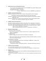
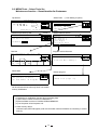
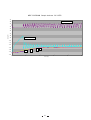
2-1. MENU/Tools – Select Tools Svc
Temperature calibration, Service function - Secret function for Customers
0
1
Top Screen
0
2
1
1
1
2
1
3
1
4
1
5
1
6
1
7
To p
1
T e mp
2
3
- 1 5 0
o
1
8
1
9
2
0
2
1
5
2
3
2
4
2
5
2
6
2
7
2
8
2
9
3
0
3
1
3
2
3
3
3
4
3
5
3
6
3
7
3
8
3
9
4
0
0
1
St a t us 䋺
Do o r 䋺
0
1
0
2
0
3
0
4
0
5
0
6
0
7
0
8
0
9
1
0
1
1
1
2
1
3
1
4
1
5
1
6
1
7
1
8
1
9
2
0
2
1
2
2
2
3
2
4
2
5
2
6
2
7
2
8
2
9
3
0
3
1
3
2
3
3
3
4
For
3
5
3
6
3
7
3
8
3
9
Se r v i c e
Da t e
5
Ke y
0
8
0
9
1
0
1
1
1
2
1
3
1
4
Tool s
Tool s
Status indication
0
3
0
4
0
5
0
6
0
7
0
8
0 1
9 0
1
1
1
2
1
3
1
4
1
5
1
6
1
7
1
8
H a r d wa r e
St a t us
T e mp
- 1 5 0 . 0 㫦C
SV
T e mp
1
9
2
0
T e mp
2 5 . 0 㫦C
Ca s
T e mp
- 3 5 . 0 㫦C
㩷 Fi l
T e mp
3 5 . 0 㫦C
Ca p i . H
OF F
2
2
2
3
2
4
2
5
C o mp
- 1 5 0 . 0 㫦C
PV
A mb
2
1
2
6
2
7
2
8
2
9
SV
C o mp
3
0
3
1
3
2
3
3
3
4
PV
3
6
3
7
3
8
3
9
6 䋯
6 6 %
PW
Lo c k
Calibration 2
0
2
0
3
0
4
0
5
0
6
0
7
0
8
0
9
1
0
1
1
1
2
1
3
1
4
1
5
1
6
1
7
1 1
8 9
2
0
1 da y
1 da y
1
Ca l i b r a t i o n
3
Ca p i
H . T i me r
8
Ca p i
H. St a r t
0
4
L . C o mp
5
E_ L oc k
㩷
6
Mo d e l
2
Op t i o n
Co d e
Fun c t i on
2
1
2
2
2
3
2
4
2
5
L . C o mp
2
6
2
7
2
8
2
9
3
0
2
0
2
1
2
2
2
3
2
4
2
5
2
6
2
7
2
8
2
9
3
0
3
1
3
2
3
3
3
4
3
5
3
6
3
7
3
8
3
9
4
0
M ENU
Sv c
Ca nc e l
Se t t i ng
Se t t i ng
0
2
0 0
3 4
0
5
0
6
0
7
0
8
0
9
1
0
1
1
1
2
1
3
1 5 0 0
3
1
3
2
3
3
3
4
3
5
3
6
3
7
Ca l i b r a t i o n
1
4
Ca l i b r a t i o n
2
5
Te s t
6
F l a s h 䋯W r i t e
0
1
Tool s
0
M ENU
6 - 1 5 mi n )
OK
( 0 . Au t o 1 . ON)
Ca n c e l
( 0 . Au t o 1 . ON)
1
( 0 . OF F
2
( 1 . 1 1 5 6
2 . 2 1 5 6 )
0
( 4 0 9 . BC
4 1 9 . F C)
1
7
1
8
0
2
0
3
Calibration 1
0
4
0
5
0
6
1
9
2
0
2
1
2
2
2
3
2
4
2
5
2
6
2
7
2
8
3
2 0
9
3
1
3
2
3
3
V e r . 㪁㩷 㪅㩷 㪁㩷 㪁㩷 㪯㩷
Sv c
3
4
3
5
3
6
3
7
3 3
8 9
4
0
M ENU
OK
Ca n c e l
Da t a
0 0
7 8
0
9
1
0
1
1
1
2
1
3
Ca l i b r a t i o n
3
C h a mb e r
5
1
6
Pr ogr a m
1
6
3 3
8 9
1
5
St a t us
㩷
OF F
1
4
Se l e c t
3
Indication for Internal temp, Ambient temp, Cascade
temp, Filter temp, Power supply voltage, Compressor
status, Compressor running rate, Battery accumulating
time, Fan motor accumulating time and battery life
0
1
1
9
Se t t i ng
3
4
F AN
ON
1
8
M DF - 2 1 5 6
1
4
0
1 0 0 %
Ba t t e r y
H . C o mp
3
5
O N 䋯O F F
9 0 %
P o we r
1
7
OK
I n i t i a l i z e
6
0
2
1
6
Select Tools for service
Ca n c e l
P a ss wo r d
0
1
1
5
T i me
Loc k
0
1
OK
4
5
0
7
㩷 㩷 㩷 㩷
4
4
0
M ENU
2
3
0
6
6
P as s wo r d
1
0
5
De f a u l t
1 2 : 0 0 : 0 0
Password (for service): 384
0
4
Se l e c t
㩷
2 0 0 6 / 0 7 / 0 1
6
0
3
3 㩷 㩷
Se t
N o r ma l
Lo g
St a nd- by
To ol s
Cl o s e d
A l a r m䋺
Select Tools㩷 㩷 (* Lock Setting is option)
0
2
1
M ENU
C
−150℃
4
2
2
Sc r e e n
Pr ogr a m
1
4
T e mp
1
5
1
6
1
7
1
8
1
9
2
0
2
1
2
2
2
3
2
4
2
5
2
6
2
7
2
8
2
9
3
0
3
1
- 1 5 2 . 5
o
C
C
1
0 . 0
A mb l e n t
T e mp
0 . 0
2 5 . 0
o
Ca s c a d e
T e mp
0 . 0
- 3 5 . 0
o
C
Fi l t e r
T e mp
0 . 0
3 5 . 0
o
C
Po we r
An a l o g
Suppl y
5 0 0
T e mp
5 0 0
3
2
3
3
3
4
3
5
3
6
3
7
3
8
3
9
4
0
M ENU
0 . 0
OK
0 . 0
Ca n c e l
0 . 0
0 . 0
1 0 0%
Calibration for Intermal temp, Ambient temp, Cascade
temp and Filter temp
4
0
Function #
0
101
102
( 0 . OF F
1 . ON)
103
104
Capi H.Timer: Cap. tube heater ON time
㩷
Setting range: 6䌾15min. (Initial: 8min.)
Capi H.Start: Operation of Cap. tube heater
0: ON every 18hrs.
1: Forcibly ON
2: OFF
E_Lock Option: Usage of Digital Lock (Option)
0: Unused㩷
1: Used
Model Code: Products model code
1: MDF-1156ATN
2: MDF-C2156VAN
Function:
㩷 Indications of Key lock Password and Master ID
Password
Reset for battery and fan motor accumulating
time, Memory initialization
27
105
409
419
925
Function
Mode for shipment
Key lock Password is indicated forcibly
Master ID and Password are indicated
forcibly
Log indication
(Cascade temp, Ambient temp)
Log Address is indicated during data
ransmission to PC
Digital Lock Password is indicated
during data transmission to PC
Reset battery replacement
Reset fan motor replacement
Non-volatile memory initialization
Set ‘925’ and perform ‘MENU/Tools Svc - Initialize All Data’ to initialize
value. Repower unit to set initial value.
Function # automatically reverts to ‘0’
after initialization done.
<Note> You should perform Temp.
Calibration because temp. calibration
value is also initialized.
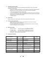
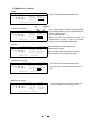
2-2. MENU/Tools – Select Tools Svc
Maintenance function – Secret function for Customers
Top Screen
0
1
0
2
1
1
1
2
1
3
1
4
1
5
1
6
1
7
To p
1
T e mp
2
3
- 1 5 0
o
1
8
1
9
2
0
2
1
2
3
2
4
2
5
0
2
0
3
0
4
0
5
0
6
0
7
0
8
0
9
1
0
1
1
1
2
1
3
2
7
2
8
2
9
3
0
1
4
1
5
1
6
3
1
3
2
3
3
1
7
St a t us 䋺
1
9
2
0
2
1
2
2
2
3
3
5
3
6
3
7
3
8
3
9
4
0
2
4
2
5
䋺
0
1
0
2
Select Tools㩷 㩷 (* Lock Setting is option)
0
3
2
8
2
9
3
0
0
6
0
7
0
8
0
9
1
0
1
1
1
2
1
3
1
4
1
5
1
6
1
7
Too l s
1
8
1
9
2
0
2
1
2
2
2
3
2
4
2
5
2
6
2
7
2
8
2
9
3
0
3
1
3
2
3
3
Da t e
5
Ke y
3
6
3
7
3
8
3
9
Se t t i ng
Sv c
Lo c k 䋮
PW
Ca n c e l
Se t t i ng
Se t t i ng
6
3
1
3
2
3
3
3
4
3
5
3
6
3
7
3
8
3
9
0
1
4
0
M ENU
OK
Ca n c e l
0
2
0
3
0
4
0
5
0
6
0
7
0
8
0
9
1
0
1
1
1
2
1
3
1
4
1
5
1
6
1
7
1
8
1
9
Select Tools for service
1
Se l e c t
3
St a t us
4
1
Ca l i b r a t i o n
2
2
2
2
3
2
4
2
5
2
6
2
7
2
8
M
OK
Ca
3
0
U
el
2
9
3
1
3
2
3
3
3
4
3
5
3
6
3
7
3
8
3
9
4
0
M ENU
OK
Ca nc e l
Pr og r a m
I n i t i a l i z e
Da t a
F l a s h 䋯W r i t e
6
2
1
V e r . 㪁㩷 㪅㩷 㪁㩷 㪁㩷 㪯㩷
Sv c
Ca l i b r a t i o n
Te s t
5
To ol s
2
0
Pr ogr a m
㩷
Test Run
Program version Renewal
㩷
㩷
㩷 For Facotry test
㩷
Delete data
Reboot program
㩷
㩷
㩷
Repower unit after reboot is done
Please refer to <Note!>
should use this function only when non-volatile
㩷 You
memory initialization
㩷
㩷 <Note!>㩷
1. Initialization for Calibration data and all accumulating data
(1) Set Function # ‘925’ at screen of ‘Calibration 2’.
Erase all data at screen of ‘Initialize All Data MENU/OK’.
㩷 (2)
(3) Cut the power off and repower unit.
㩷 2. Flash memory reboot
0
1
0
2
0
3
0 0
4 5
1 Te s t
o
2 C
0
6
0
7
0
8
0
9
1
0
1
1
1
2
1
3
1
4
1
5
1
6
1
7
Pr ogr a m
r un
1
8
1
9
2
0
2
1
2
2
2
3
Cy c
2
4
2
5
2
6
2
7
2
8
2
9
1 / 1
3
0
3
1
3
2
3
3
De c
3
4
3
5
3
6
3
7
3
8
3
9
4
0
M ENU
3
8 6 : 0 0
6 T e mp
- 15 0
- 1 6 0
0
1
0
2
0
3
0
4
- 1 6 0
0
5
0
6
0
7
0
8
0
9
1
0
1
1
1
2
1
3
1
4
1
5
1
6
1
7
1
8
1
9
2
0
2
1
Al l
Us e r
s ur e
Ar e
2
2
2
3
2
4
2
5
2
6
2
7
2
8
2
9
3
0
3
1
3
2
3
3
3
4
3
5
3
6
3
7
3
8
3
9
d e l e t e
4
0
1
a nd
0
9
1
0
1
1
1
2
1
3
1
4
1
5
1
6
1
7
1
8
1
9
2
0
2
1
2
2
2
3
2
4
2
5
2
6
2
7
2
8
2
9
3
0
3
1
3
2
3
3
y ou
s ur e
3
4
3
5
3
6
3
7
M ENU
t o
Ca n c e l
Wr i t e
a nd
M e mo r y
?
0
2
0 0
3 4
0
5
0
6
0
7
0
8
0
9
1
0
1
1
1
2
1
3
1
4
1
5
1
6
1
7
1
8
1
9
2
0
2
1
2
2
2
3
2
4
2
5
2
6
2
7
2
8
2
9
3
0
3
1
3
2
3
3
3
4
3
5
3
6
3
7
3 3
8 9
3
Ca n c e l
P r o g r am s
Re b o o t
a f t e r
p r ogr a mi ng.
5
㩷
6
㩷
㩷
3 3
8 9
OK
1
OK
4
N a me s
0
8
Fl a s h
4
0
M ENU
t o
0
7
6
2
y ou
0
6
㩷
C on f i r ma t i o n
Ar e
0
5
C o n f i r ma t i o n
5
4 : 0 0
5
0 0
3 4
4
4
3
0
2
3
Ca n c e l
1
0
1
1
St a r t
5 T i me 2 4 : 0 0
4
0
M ENU
T i me
Loc k
3
5
OK
De f a u l t
4
3
4
M DF - 2 1 5 6
㩷 㩷 㩷 㩷
㩷
2
7
0
5
3 㩷 㩷
0 0 : 0 0
2
6
0
4
Se l e c t
1
Se t
N o r ma l
Lo g
St a nd- by
To ol s
Cl o s e d
A l a r m䋺
1
8
3
4
M ENU
Do o r
㩷5
㩷
2 0 0 6 / 0 7 / 0 1
1 2 :
6
㩷
㩷 Password (for service): 384
㩷 1 P as s wo r d
㩷2
Fo r
Se r v i c e T o o l s
3
㩷4
㩷 5 P a ss wo r d
㩷
6
㩷
0
1
2
6
C
−150℃
4
2
2
Sc r e e n
6
㩷
Interface board, MTR-480 (option) and communication cable for RS232C are necessary to reboot
memory.
28
4
0
4
0
㩷
㩷
㩷
㩷
㩷
1
㩷2
㩷3
㩷 45
㩷
㩷6
㩷
㩷
㩷
㩷1
㩷2
㩷3
4
㩷5
㩷
6
㩷
㩷
㩷
㩷
1
㩷2
㩷3
㩷4
5
㩷
㩷6
㩷
㩷
㩷
㩷1
2
㩷3
㩷4
㩷5
㩷6
㩷
㩷
㩷
㩷
㩷
㩷 1
㩷 2
3
㩷 4
㩷 5
㩷
6
㩷
㩷
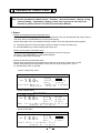
3-1 Digital Lock – Unlock
Locked
0
1
0
1
0
1
0
2
1
1
1
2
1
3
1
4
1
5
o
C
1
6
1
7
1
8
To p
T e mp
- 1 5 0
1
9
2
0
2
1
2
2
2
3
2
4
2
5
2
6
2
7
2
8
2
9
3
0
3
1
Sc r e e n
3
3
3
4
3
5
3
6
3
7
1
1
1
2
1
3
1
4
1
5
1
6
1
7
1
8
To p
T e mp
- 1 5 0
o
1
9
2
0
St a t us 䋺
St a nd- by
Loc k e d
2
1
2
2
1
1
1
2
1
3
- 1 5 0
o
1
4
1
5
1
6
1
7
1
8
1
2
1
3
1
4
o
- 1 5 0
1
9
2
0
2
1
1
5
1
6
1
7
1
8
Password
1
2
- 1 5 0
3
2
3
3
3
4
3
5
3
6
3
7
3
8
3
9
4
0
Input ID and Password without pressing ENTER
key to indicate digits one by one. Press ENTER key
after all 7 digits are input.
(Ex. ID 123, Password * * * *)
N o r ma l
St a nd- by
Do o r 䋺
Loc k e d
Note) If you don’t press ENTER key within 30
seconds since you input 1st digit of ID, buzzer
beeps to revert to STANDBY automatically.
2
2
2
3
2
4
2
5
2
6
2
7
2
8
2
9
3
0
3
1
3
2
3
3
3
4
3
5
3 3
6 7
3
8
3
9
4
0
Buzzer beeps with unlocked after ID and
Password input correctly.
L oc k - Fr e e
A l a r m䋺
N o r ma l
St a t us 䋺
St a n d- b y
Do o r 䋺
Cl o s e d
1
9
Note) If you don’t open door within 30 seconds
since unlocked, buzzer beeps to lock again.
2
0
2
1
2
2
2
3
2
4
2
5
2
6
2
7
2
8
2
9
3
0
3
1
3
2
3
3
3
4
3
5
3
6
3
7
3
8
3
9
4
0
L oc k - Fr e e
The screen shows unlocked and door open.
Note) You cannot input ID and Password at the
time.
C
1
3
1
4
1
5
1
6
1
7
To p
T e mp
3
1
1 2 3 - 䋪䋪䋪䋪
Sc r e e n
Digital Lock is unused
1
1
3
0
St a t us 䋺
A l a r m䋺
N o r ma l
St a t us 䋺
St a nd- by
Do o r 䋺
Op e n
2 0 0 6 / 0 7 / 0 1
0
2
2
9
1 2 : 0 0 : 0 0
−150℃
0
1
2
8
C
To p
T e mp
2
7
Sc r e e n
Unlocked and door open
1
1
2
6
A l a r m䋺
2 0 0 6 / 0 7 / 0 1
0
2
2
5
1 2 : 0 0 : 0 0
−150℃
0
1
2
4
C
To p
T e mp
2
3
Sc r e e n
2 0 0 6 / 0 7 / 0 1
0
2
䊶Door is closed with locked (Solenoid OFF)
1 2 : 0 0 : 0 0
−150℃
Unlocked
4
0
N o r ma l
ID
Input ID and Password
3
9
Do o r 䋺
2 0 0 6 / 0 7 / 0 1
0
2
3
8
S T ANDBY
A l a r m䋺
−150℃
3
2
o
1
8
1
9
1 2 : 0 0 : 0 0
2
0
2
1
2
2
2
3
2
4
2
5
2
6
2
7
2
8
2
9
3
0
Sc r e e n
3
1
3
2
3
3
3
4
3
5
3
6
3
7
3
8
3
9
E L - OF F
The screen shows Digital Lock is unused when
you set ‘0’ (Disable) in Lock Setting screen.
C
−150℃
2 0 0 6 / 0 7 / 0 1
4
0
A l a r m䋺
N o r ma l
St a t us 䋺
St a nd- by
Do o r 䋺
Cl o s e d
1 2 : 0 0 : 0 0
29
㩷
㩷
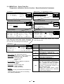
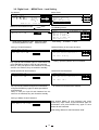
3-2.
Digital Lock -㩷 MENU/Tools - Lock Setting㩷
㩷
㩷 Top Screen
Select Tools
Se l e c t
Tool
To p Sc r e e n
㩷1
1
M ENU
㩷 㩷
㩷 㩷 㩷 㩷
T e mp - 1 5 0 C
3
2
㩷
Se t
De f a u l t
Se t
A l a r m䋺
N o r ma l
3
Lo g
㩷4
S
D
a
t
e
T
i
m
e
t
a
t
u
s
S
t
a
n
d
b
y
䋺
4
℃
To ol s
0
1
0
2
1
1
1
2
1
3
1
4
1
5
1
6
1
7
1
8
1
9
2
0
2
1
2
2
2
3
2
4
2
5
2
6
2
7
2
8
2
9
3
0
3
1
3
2
3
3
3
4
3
5
3
6
3
7
3
8
3
9
0
1
4
0
0
2
0 0
3 4
0
5
0 0
6 7
0
8
0
9
1
0
1
1
1
2
1
3
1
4
1
5
1
6
s
1
7
1
8
1
9
2
0
2
1
2
2
2
3
2
4
2
5
2
6
2
7
2
8
2
9
3
0
3
1
3
2
3
3
㩷
5
Do o r 䋺
Cl o s e d
Ke y
5
㩷
2 0 0 6 / 0 7 / 0 1
6
1 2 : 0 0 : 0 0
Master ID and Password input
0
1
0
2
1
0
3
0
4
0
5
0
6
0
7
0
8
0
9
1
0
1
1
Ma s t e r
I D
Ma s t e r
I D
1
2
1
3
1
4
1
5
1
6
1
7
1
8
1
9
2
0
2
1
2
2
2
3
2
4
2
5
2
6
2
7
2
8
2
9
3
0
L oc k
Loc k
t i n g
3
1
3
2
3
3
3
4
3
5
3
6
3
7
3
8
3
9
Lock Setting screen
4
0
0
1
0
2
0
3
0
4
0
5
0
6
0
7
0
8
0
9
1
0
1
1
1
2
1
3
1
4
1
5
1
6
Loc k
3
Sa v e
4
4
De l e t e
h i s t or y
5
5
De l e t e
a
De l e t e
a l l Us e r
0 0 0 䋪䋪䋪䋪
6
Initial setting: Master ID ‘000’㩷 Password ‘0000’
Secondary Master ID ‘384Ĺ’㩷 Password ‘384ĸ’
0
2
0
3
0
4
0
5
0
6
0
7
Sa v e
1
0
8
0
9
1
0
1
1
1
2
Us e r
1
3
1
4
1
5
I D
1
6
1
7
1
8
1
9
2
0
2
1
2
2
2
3
2
4
2
5
2
6
2
7
2
8
2
9
3
0
Ca n c e l
3
1
3
2
3
3
3
4
3
5
3
6
3
7
3
8
1
7
1
8
1
9
2
0
2
1
2
2
2
3
2
4
2
5
2
6
2
7
2
8
2
9
3
0
3
1
3
2
Us e r
U se r
I D
3
9
0
2
Us e r
ma s t e r
I D
3
PW
4
4
5
5
6
6
0
2
0
3
0
4
0
5
0
6
0
7
0
8
0
9
De l et e
1
1
0
1
1
1
2
1
3
1
4
Us e r
1
5
1
6
1
7
1
8
1
9
2
0
2
1
2
2
2
3
2
4
2
5
2
6
2
7
2
8
2
9
3
0
3
1
3
2
3
3
3
4
3
5
3
6
3
7
3
8
3
9
I D
I D
I D
1
PW
+
4
0
HI S
PC
I D
3
9
4
0
3
9
4
0
I D
0
3
0
4
0
5
0
6
0
7
0
8
0
9
1
0
1
1
1
2
1
3
1
4
1
5
1
6
1
7
1
8
1
9
2
0
2
1
2
2
2
3
2
4
2
5
2
6
2
7
2
8
2
9
3
0
3
1
3
2
3
4
4
5
5
6
6
Input specified ID and Password then press ENTER
key. Input ID and Password again for confirmation
and press ENTER key again to delete specified ID
and Password.
Note) In case your input ID and Password are not
saved or not matched, they are cleared to standby.
3
3
Ar e
y ou
Al l
Us e r
3
4
3
5
3
6
3
7
3
8
M ENU
s ur e
t o
de l e t e
OK
?
Ca n c e l
Hi s t o r y
0
2
0
3
0
4
0
5
0
6
0
7
0
8
0
9
1
0
1
1
1
2
1
3
1
4
1
5
1
6
1
7
1
8
1
9
2
0
2
1
2
2
2
3
2
4
2
5
2
6
2
7
2
8
2
9
3
0
C o n f i r ma t i o n
Ar e
y ou
Al l
Us e r
s ur e
I D
3
1
3
2
3
3
3
4
3
5
3
6
3
7
3
8
M ENU
2
U se r
3
9
Ca nc e l
Delete all ID and Password
0
1
4
0
2
3
3
8
History opened by Master ID is not deleted.
Input desired ID and Password then press ENTER
key. Input ID and Password again for confirmation and
press ENTER key again to save ID and Password.
Note) In case your input ID and Password are already
saved or not matched, they are cleared to standby.
0
1
3
7
PC
C o n f i r ma t i o n
1
Delete specified ID and Password
3
6
OK
Delete all history of door open-and-shut
0
1
4
0
a s
+
3
5
M aE bN lU e 䋩
1 . En
䋨 0 . Di s a b l e
I D
2
Ne w
3
4
Lock setting: 0: Disable 1䋺Able
2
3
3
3
i ng
1
a
Sa v e
6
Saving of ID and Password
4
0
Se t t i ng
2
0
1
3 3
8 9
6
2
PW
3
7
Sv c
Se t t i ng
L o c k. S e t t
+
3
6
OK
1
3
3
5
M ENU
o
−150
3
4
M DF - 2 1 5 6
t o
de l e t e
?
OK
Ca n c e l
?
All saved ID and Password is deleted.
Saving of Master ID and Password
0
1
1
0
2
0
3
0
4
0
5
0
6
Sa v e
0
7
0
8
0
9
1
0
1
1
1
2
1
3
Ma s t e r
1
4
1
5
1
6
1
7
1
8
1
9
2
0
2
1
2
2
2
3
2
4
2
5
2
6
2
7
2
8
2
9
3
0
3
1
3
2
3
3
3
4
3
5
3
6
3
7
3
8
3
9
4
0
Input desired Master ID and Password and press
ENTER key. Input master ID and Password again for
conformation and press ENTER key again to save
Master ID and Password.
I D
2
3
Ne w
Ma s t e r
I D
+
PW
4
5
Initial setting: Master ID ‘000’ Password ‘0000’
6
30
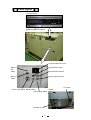
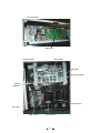
Parts layout
䋼Control panel䋾
Digital temperature indicator
Communication box cover
Back-up
test
switch
Remote alarm switch
Back-up
switch
Analog output terminal
Remote alarm terminal
AT sensor
Temp. control knob Battery switch
<Grille>
Power supply switch
Exhaust air vent
31
䋼Control BOX䋾
Main PCB
䋼Electric BOX䋾
12P terminal
Noise filter
Running capacitor
Starting
Capacitor
Compressor H
Fan motor
Filter sensor
Compressor L
32
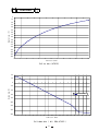
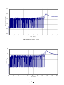
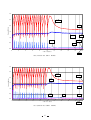
Test Data
0
-10
-20
-30
-40
Chamber temp. (℃)
-50
-60
-70
-80
-90
-100
-110
-120
-130
-140
-150
-160
0
1
2
3
4
5
6
7
Time scale (hour)
8
9
10
11
12
Pull-up data(AT30℃)
40
20
0
Chamber temp.(℃)
-20
-40
1/2air temp.
-60
-80
-100
-120
-140
-160
0
1
2
3
4
5
6
7
8
9
10
11
12
Time scale (hour)
13
14
Pull-down data ( Φ3, 50Hz AT30℃ )
33
15
16
17
18
19
20
㩷
㩷
㩷
㩷
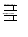
㩷 㩷 㩷 㩷 㩷 㩷 * Temperature uniformity for MDF-C2156VAN
Conditions: (chamber air temp. 㱢3, 50Hz , AT30㷄)
䋭147㷄
䋭146㷄
䋭149㷄
䋭149㷄
䋭150㷄
䋭150㷄
䋭149㷄
䋭150㷄
䋭151㷄
㩷 㩷 㩷 㩷 㩷 * Temperature variation for MDF-C2156VAN
Conditions: (chamber air temp. 㱢3, 50Hz, AT30㷄)
+2㷄
-150㷄
-2㷄
㩷
34
2.0
POWER CONSUMPTION (kW)
1.5
1.0
0.5
0.0
0
2
4
6
8
10
TIME (hour)
12
14
16
18
20
16
18
20
POWER CONSUMPTION (220V50Hz, AT30℃)
10
CURRENT (A)
8
6
4
2
0
0
2
4
6
8
10
TIME (hour)
12
CURRENT (220V50Hz, AT30℃)
35
14
2.5
POWER CONSUMPTION (kW)
2.0
1.5
1.0
0.5
0.0
0
2
4
6
8
10
TIME (hour)
12
14
16
18
20
POWER CONSUMPTION (220V60Hz, AT30℃)
10
CURRENT (A)
8
6
4
2
0
0
2
4
6
8
10
TIME (hour)
12
CURRENT (220V60Hz, AT30℃)
36
14
16
18
20
3.0
2.5
L-pd
1.70
Pressure(MPa)abs
2.0
1.5
H-pd
1.38
1.0
L-ps
0.17
0.5
H-ps
0.0
0
2
4
6
8
10
Time scale(hour)
12
14
16
18
20
0.10
Unit pressure data (50Hz, AT30℃)
3.0
2.5
L-pd
1.70
Pressure(MPa)abs
2.0
H-pd
1.5
1.45
1.0
0.5
L-ps
H-ps
0.15
0.0
0
2
4
6
8
10
Time scale (hour)
12
Unit pressure data (60Hz, AT30℃)
37
14
16
18
20
0.10
㪤㪛㪝㪄㪚㪉㪈㪌㪍㪭㪘㪥㩷㩷㩷㪪㪸㫄㫇㫃㪼㩷㫃㫆㪸㪻㩷㫋㪼㫊㫋㩷㪄㩷㪧㫌㫃㫃㪄㪻㫆㫎㫅
㪘㪫㪑㩷㪊㪇㷄
㪣㫆㪸㪻㪑㩷㪌㪇㪇㫄㫃㩷㬍㪋㪇㩷㪹㫆㫋㫋㫃㪼㫊㩷㪔㩷㪉㪇㪣㩷㫎㪸㫋㪼㫉
㪤㪼㪸㫊㫌㫉㫀㫅㪾㩷㫇㫆㫀㫅㫋㪑㩷㪚㪼㫅㫋㪼㫉㩷㫆㪽㩷㪼㪸㪺㪿㩷㪹㫆㫋㫋㫃㪼
㪉㪇
㽴
㽵
㪇
㽲
㪄㪉㪇
㽳
䌈㩷䌅䌶䌡㩷䌯䌵䌴
䌴䌥䌭䌰䋨㷄䋩
㪄㪋㪇
㪄㪍㪇
④
䌌㩷䌅䌶䌡㩷䌯䌵䌴
㪄㪏㪇
③
㪄㪈㪇㪇
②
㪄㪈㪉㪇
①
㪄㪈㪋㪇
㪄㪈㪍㪇
㪇
㪈㪇
㪉㪇
㪊㪇
㪋㪇
㪌㪇
㪍㪇
㪎㪇
㪏㪇
䌴䌩䌭䌥䋨䌈䌲䋩
㪤㪛㪝㪄㪚㪉㪈㪌㪍㪭㪘㪥䇭㪪㪸㫄㫇㫃㪼㩷㫃㫆㪸㪻㩷㫋㪼㫊㫋䇭㪪㪭㪑㪄㪈㪌㪇㷄
㪄㪈㪇
㪄㪉㪇
䌈㩷䌅䌶䌡㩷䌯䌵䌴
㪄㪊㪇
㪄㪋㪇
㪄㪌㪇
㪄㪍㪇
䌴䌥䌭䌰䋨㷄䋩
㪄㪎㪇
㪄㪏㪇
㪄㪐㪇
㪄㪈㪇㪇
㪄㪈㪈㪇
㪄㪈㪉㪇
䌌㩷䌅䌶䌡㩷䌯䌵䌴
㪄㪈㪊㪇
㪄㪈㪋㪇
㪄㪈㪌㪇
㪄㪈㪍㪇
㪇㪅㪇
㽲
㪈㪅㪇
㪉㪅㪇
㪊㪅㪇
㪋㪅㪇
㽳
㽴
㪌㪅㪇
䌴䌩䌭䌥䋨䌈䌲䋩
38
㽵
㪍㪅㪇
㪎㪅㪇
㪏㪅㪇
㪐㪅㪇
㪈㪇㪅㪇
㪤㪛㪝㪄㪚㪉㪈㪌㪍㪭㪘㪥䇭㪪㪸㫄㫇㫃㪼㩷㫃㫆㪸㪻㩷㫋㪼㫊㫋䇭㪪㪭㪄㪈㪉㪌㷄
㪄㪈㪇
㪄㪉㪇
䌈㩷䌅䌶䌡㩷䌯䌵䌴
㪄㪊㪇
㪄㪋㪇
㪄㪌㪇
㪄㪍㪇
䌴䌥䌭䌰䋨㷄䋩
㪄㪎㪇
㪄㪏㪇
䌌㩷䌅䌶䌡㩷䌯䌵䌴
㪄㪐㪇
㪄㪈㪇㪇
㪄㪈㪈㪇
㪄㪈㪉㪇
㪄㪈㪊㪇
㪄㪈㪋㪇
㽲
㽳
㽴
㽵
㪄㪈㪌㪇
㪄㪈㪍㪇
㪇
㪉
㪋
㪍
䌴䌩䌭䌥䋨䌈䌲䋩
39
㪏
㪈㪇