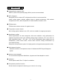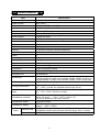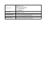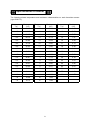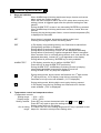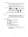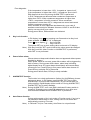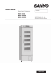
1
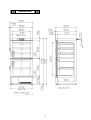
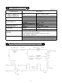
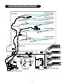
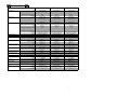
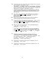
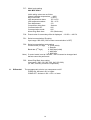
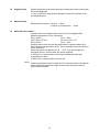
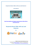
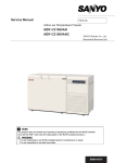
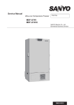
Service Manual
Biomedical Freezer
MDF-U5411
FILE No.
MDF-U5411
SM9910028
Effective models
This service manual is effective following models.
Model
MDF-U5411
Product code
823 171 51
823 171 52
823 171 54
823 171 55
823 171 56
823 171 57
823 171 58
823 171 59
Voltage and Frequency
110/115V
60Hz
220V
50Hz
230/240V
50Hz
240V
50Hz
230/240V
50Hz
220V
50/60Hz
240V
50Hz
110/115V
60Hz
Features
■ Large effective capacity: 482L
280 FFP (fresh frozen plasma) bags (300mL) can be accommodated.
■ HFC refrigerant
Refrigerant circuit contains HFC refrigerant that effect to environment little.
Latest cooling system reduces negative factor to global environment. With ambient
temperature at 30℃, while temperature of inside chamber maintains -40℃.
■ PCM structure
PCM structure reduces amount of organic solvent.
■ Temperature control function
New cooling system realizes to set -20℃, which is suitable for reagent preservation.
■ Specification unified
Unified specification for same categories, which also realized to unify performance for
high/low temperature alarm (the available setting range is between +5℃ and +15℃ for
high temperature alarm, -5℃ and -15℃ for low temperature alarm against the set
temperature), power failure alarm, remote alarm terminal, setting memorization by
non-volatile memory.
Adopt new microprocessor system for display panel and keypad makes operation easily.
■ Self diagnosis function
Abnormal condition for temperature sensor is indicated as E1/E2 by self-diagnosis
system.
■ Ambient sensor adopted
For much better temperature distribution, by-pass circuit has adopted to control.
■ Validation
Control panel enable Zero “0” Adjust for validation.
■ Compressor protection function
Sensor detects compressor’s warming up to control unit running.
1
Specifications
Item
Specification
Model description
Biomedical freezer
Model Number
MDF-U5411
Exterior dimensions
W 804 × D 772 × H 1802 mm
Interior dimensions
W 658 × D 607 × H 1272 mm
Effective chamber capacity
482 liters (17.0cu.ft)
Exterior cabinet
Polyester finish baked on zinc galvanized steel
Interior cabinet
Polystyrene resin
Outer door
2, Polyester finish baked on zinc galvanized steel
Door latch
2
Door lock
1
Cabinet insulation
Rigid polyurethane foam
Shelves
4, aluminum shelves (used as evaporator)
Access hole
φ 30mm, rear side
Caster
4
Leveling legs
2
Net weight
131 Kg
Evaporator
Tube on sheet type
Condenser
Wire and tube type
Compressor
350W hermetically sealed
Refrigerant
R-404A (HFC refrigerant)
Refrigerator oil
Ze-NIUS32SA
Door lock key, defrost spatula
Accessories
6 small baskets for upper room chamber (W290 x D536 x H136 mm)
4 large baskets for lower room chamber (W290 x D536 x H238 mm)
Power supply
Single phase, local voltage
Internal 1/2h air: -40℃
Cooling performance
(AT +30℃, no load, not exposed to direct rays of sun)
Internal temperature control -20℃~-40℃
range
(AT +5℃~+30℃, RH 80% or lower)
Microprocessor controlled system with non-volatilized memory.
Temperature controller
Temp. set range : -18℃~-45℃ (unit by 1℃)
SV can be stored for more than 10hours.
Temperature sensor
Thermistor sensor
LED digital display (green colored) , unit by 1℃.
Temperature display
Range : -50℃~+50℃
±5℃~±15℃ adjustable. (Initial:±10℃)
High/low temp.
Alarm
ALARM lamp brinks and intermittent buzzer beeps 15min. of delay
Power failure
ALARM lamp brinks and intermittent buzzer beeps
2
Operation panel
Key lock function
Remote alarm contact
Self diagnosis function
Compressor protect sensor
Optional component
ALARM lamp blinks in temperature alarm
BUZZER: Buzzer key
ALARM TEST: Alarm test key
SET: To switch the SV and PV
>: To shift the set digit
∧: To change the SV
DEF: Defrost key
Press >key for 5 seconds
L0: Unlock
L1: Lock
DC30V, 2A, Normal-Open, temperature alarm & power failure alarm
When each sensor is in fault:
Error code and PV are displayed alternately.
Thermistor sensor
Circular recorder: MTR-G85
Metal fittings for G85 circular recorder: MPR-S7
3
Dimensions
4
Refrigeration circuit
Unit:mm
Parts description
Evaporator
Upper (1), Middle (2),
Lower (1), Bottom (3)
Specification
Type
9lines×1column×5pcs
Material
Aluminum (φ 8.0)
Dry core
Type
D-S032T
Solid core
50cm2
Capillary tube
Resistance
0.725MPaG (7.4Kgf/cm2G)
(Total number: 2)
Dimension
φ 1.8×L4500
Resistance indicator color
Blue
Condenser assembly front Type
Wire and tube
w
(Total number: 4)
480×P40×6 columns
Dimension
Frame pipe
Material
C1220T
Dimension
φ 4.0×t0.5×L7470
Evacuation and vacuum Evacuation time: more than 20min. by 2 ports (high pressure and
pressure
low pressure side). (N2 exchange)
When charged, vacuum pressure is lower than 1.0torr
(pump capacity: 300L/min)
Refrigerant and oil
Refrigerant : R-404A
Charged q’ty : 278±5g
Oil : Ze-NIUS32SA
Charged q’ty : 280±10cc
Oil additive: n-pentane
Charged q’ty: 19cc (11.6g)
Refrigeration circuit principle diagram
5
Refrigeration circuit welding points
Evaporator (upper)
Frame pipe
EI
EA
Evaporator (lower)
FB-1
EB
Evaporator (middle)
EC
FB-2
EE
Blue colored
EF
ED
EG
Evaporator (middle)
EH
FB-3
EO
FB-4
EJ
Evaporator (bottom)
HO
Header
HI
Capillary tube
FO
FI
PI
CO
PO
B7
C4
B8
B6
DD
HI
OA
A1
A2
A3
OB
OI
DO
DI
KL
KI
KU
Solenoid valve
AI
OO
Dry core
CB
CA
B5
C3
GO
B4
DB
DA
B3
C2
SB
GI
SA
CC
AO
DP
Compressor
C1
Check valve
blue colored
6
B1
B2
Condenser 4pcs
Electrical Parts
MDF-U5411
Compressor
Starting relay
Type
Code
Rated voltage (50/60Hz)
Winding resistance C-S(Aux)
C-R(Main)
Type
Pick up voltage
Drop out voltage
Overload relay
Starting capacitor
Running capacitor
Compressor relay
Temp. control relay
Switching power supply
Temperature sensor
Solenoid valve control
sensor
Compressor protect
sensor
PCB
Battery
Battery switch
Breaker switch
Solenoid valve coil
(2pcs)
Condensing fan motor
AC110V/115V, 60Hz
AC220V, 50/60Hz
AC230V/240V, 50Hz
C-2SN350L0R
807 764 20
C-2SN350L5S
807 763 25
C-2SN350L5S
807 763 25
5.8Ω
1.6Ω
AMVL-180A
AC91V~111V
AC108V~128V
AC30~65V
AC30~75V
P18AU
30.6Ω
7.8Ω
AMVL-300A
AC185V~217V
AC215V~232V
AC60~120V
AC69~132V
P10MU
30.6Ω
7.8Ω
AMVL-300A
AC185V~217V
AC215V~232V
AC60~120V
AC69~132V
P10MU
130±8℃
69±10℃
10A
6~15seconds
130±8℃
69±10℃
10A
6~15seconds
2.5A more than 30minutes
3.4A within 15minutes
30μF, 300VAC
5μF, 400VAC
G4F-11123T
AC220V, 20A
DC12V
G2R-1A-T
AC250V, 10A
DC12V
ZWS10-12/J
AC100-240V 50-60Hz, 0.3A
DC12V, 0.85A
502AT-1
5KΩ, 25℃
502AT-1
5KΩ, 25℃
502AT-1
5KΩ, 25℃
DF-5411
5HR-AAC
6V 1100MAH
SLE6A2-5
AC250V 4A
BAM215131
AC250V 15A
NEVAC220V
220V 50/60Hz
FU2-A051B5MP
AC220-240V 50/60Hz
130℃
2.5A more than 30minutes
3.4A within 15minutes
30μF, 300VAC
5μF, 400VAC
G4F-11123T
AC220V, 20A
DC12V
G2R-1A-T
AC250V, 10A
DC12V
ZWS10-12/J
AC100-240V 50-60Hz, 0.3A
DC12V, 0.85A
502AT-1
5KΩ, 25℃
502AT-1
5KΩ, 25℃
502AT-1
5KΩ, 25℃
DF-5411
5HR-AAC
6V 1100MAH
SLE6A2-5
AC250V 4A
BAM215131
AC250V 15A
NEVAC240V
240V 50/60Hz
FU2-A051B5MP
AC220-240V 50/60Hz
130℃
Type
Action to the temp. (No current)
120±8℃
OFF
ON
69±10℃
Action to the current (AT25℃)
18.5A
Operation time
6~15seconds
Non-Action to the temp. (80℃)
Non-Action 4.0A more than 30minutes
Action
5.5A within 15minutes
100μF, 160VAC
Rating
25μF, 220VAC
Rating
Type
G4F-11123T
Contact capacity
AC220V, 20A
Coil
DC12V
Type
G2R-1A-T
Contact capacity
AC250V, 10A
Coil
DC12V
Type
ZWS10-12/J
Input AC100-240V 50-60Hz, 0.3A
Rated output
DC12V, 0.85A
Type
502AT-1
5KΩ, 25℃
Rating
Type
502AT-1
5KΩ, 25℃
Rating
Type
502AT-1
5KΩ, 25℃
Rating
Type
DF-5411
Type
5HR-AAC
Rating
6V 1100MAH
Type
SLE6A2-5
Rating
AC250V 4A
Type
BAM215131
Rating
AC250V 15A
Type
NEVAC120V
Rating
120V 50/60Hz
Type
FU2-A051B1MP
Rating
AC110-115V 50/60Hz
130℃
Thermal fuse
7
Specifications of sensor
The following shows temperature and resistance characteristics on each thermistor sensor
(type 502AT-1).
Temperature
(℃)
Resistance
(kΩ)
Temperature
(℃)
Resistance
(kΩ)
Temperature
(℃)
Resistance
(kΩ)
-50
154.50
-7
17.92
12
8.17
-45
116.50
-6
17.16
13
7.85
-40
88.85
-5
16.43
14
7.55
-35
68.15
-4
15.74
15
7.27
-30
52.84
-3
15.08
16
6.99
-25
41.19
-2
14.45
17
6.73
-20
32.43
-1
13.86
18
6.48
-19
30.92
0
13.29
19
6.24
-18
29.50
1
12.74
20
6.01
-17
28.14
2
12.22
25
5.00
-16
26.87
3
11.72
30
4.18
-15
25.65
4
11.25
35
3.51
-14
24.51
5
10.80
40
2.96
-13
23.42
6
10.37
45
2.51
-12
22.39
7
9.96
50
2.14
-11
21.41
8
9.57
55
1.83
-10
20.48
9
9.20
60
1.57
-9
19.58
10
8.84
-8
18.73
11
8.49
8
Control specification
1.
Keys and switches
BUZZER
When ALARM lamp is blinking and buzzer beeps, buzzer and remote
alarm output are forcibly turned off.
When the value except for 000 is set in F25 (alarm auto recovery time
setting), buzzer is triggered again after the specified setting time has
passed.
During ALARM TEST, buzzer is not silenced by BUZZER key pressed.
When ALARM lamp is blinking and buzzer is silence, buzzer does not
activate.
Pressing this key during power failure, current internal temperature(PV)
is displayed for 5seconds.
SET
Once the key is pressed, temperature setting mode is led.
Pressing this key again to store the setting value.
DEF
In PV display, keep pressing the key over 5seconds to start defrost.
(Refrigerating operation is stopped)
During defrost is performing, press the key to quit defrosting.
During defrost is performing, PV and “dF” are displayed alternately.
During defrost is performing, high/low temperature alarm is cancelled.
When a sensor error is occurred during defrost, error code and PV are
displayed alternately, instead “dF” is not appeared on the display.
During defrost is performing, BUZZER key is solely available.
ALARM TEST
In PV display, press the key to perform ALARM TEST.
Press this key to stop ALARM TEST performing.
During ALARM TEST, ALARM lamp is blinking, buzzer is beeping
intermittently and digital temperature display is turned off.
During ALARM TEST, any keys are inoperative.
During setting mode, device can be shift between the 1st digit and the
2nd digit by this key. In PV display, keep this key pressing over
5seconds to be key lock mode available. (“L0” is displayed)
During setting mode, blinking digit counts up by the key pressed.
In PV display, keep the key pressing over 5seconds to be function
mode available. (“F00” is displayed)
2.
Temperature control and temperature alarm
<Temperature control>
Setting range: -18℃~-45℃
Display range: -50℃~+50℃
Setting method: Press SET key and set the desired value with key and
key.
Press SET key again to store the setting value.
Setting mode returns to PV display.
Out of setting If a value is set out of the setting range and SET key is pressed, buzzer
range: beeps for 1second to store previous setting value.
9
<Temperature alarm>
High: When the internal temperature is higher than SV (+5℃~+15℃),
ALARM lamp and digital display are blinking. After 15min. later, buzzer
will beep and remote alarm contact will turn on. (initial: +10℃)
Low: When the internal temperature is lower than SV (-5℃~-15℃),
ALARM lamp and digital display are blinking. After 15min later, buzzer
will beep and remote alarm contact will turn on. (initial: -10℃)
Setting method: Keep
key pressing over 5seconds to be function mode available.
(“F00” is displayed) Then press
key to count value up. Set “F01” to
input value for high temperature alarm, “F02” to input value for low
temperature alarm.
Set “F01” or “F02” then press SET key to be alarm temperature setting
mode available. Set desired value with key and key.
Press SET key again to store the value.
Out of setting If a value is set out of setting range and SET key is pressed, buzzer
range: beeps for 1second to store the previous setting value.
3.
Defrosting
In PV display, keep DEF key pressing over 5seconds, defrost operation
starts. Compressor and solenoid valve are forcibly turned off.
Press DEF key again to quit defrosting. (Manual start and end)
While the refrigerating operation is stopped, the current chamber
temperature and “dF” is displayed on the control panel alternately
4.
Self diagnosis function
E01: Temperature control sensor is open circuit
E02: Temperature control sensor is short circuit
E03: Unassigned
E04: Unassigned
E05: Compressor protect sensor is open circuit
E06: Compressor protect sensor is short circuit
E07: Unassigned
E08: Unassigned
E09: Buttery switch is left turned on
E10: Compressor temperature is abnormal
E11: Solenoid valve control sensor is open circuit
E12: Solenoid valve control sensor is short circuit
When temperature control sensor is open circuit, E01 and -50℃ are
displayed alternately.
When temperature control sensor is short circuit, E02 and +50℃ are
displayed alternately.
10
Error diagnosis:
If the temperature is lower than –60℃, it regards as “open circuit”.
If the temperature is higher than +60℃, it regards as “short circuit”.
E09 diagnosis is done only during ALARM TEST is performed.
In E10, it diagnoses as abnormal when condenser temperature is
higher than +85℃. When condenser temperature is higher than
+100℃, compressor is forcibly turned off. When condenser
temperature is lower than +65℃, it diagnoses as normal and cancel
forcible compressor turning off.
When numbers of error happened simultaneously, error code of
smallest numerical digit is indicated. However, both E11 and E12 take
priority over any other error codes.
During power failure, E09 and blank are indicated.
5.
Key Lock function
In PV display, keep
key pressing over 5seconds to be Key Lock
mode available. At the time “L0” is displayed.
Press
key to display “1” … Key Lock ON
“0” … Key Lock OFF
Then press SET key to store setting value and revert to PV display.
Note) With Key Lock ON, SET mode is led but the value cannot be changed.
With Key Lock ON, either Function or ALARM TEST is performed,
while DEF is not performed.
6.
Power failure alarm
(Buzzer does not beep and indication does not appeared without power
supplied by buttery)
When power failure is occurred, power failure alarm will be triggered by
built-in buttery. During power failure alarm, alarm lamp is blinking,
digital display turns off, buzzer beeps intermittently and remote alarm
contact turns on. Press BZ key to turn power failure alarm buzzer off.
Press BZ key to display PV for 5seconds.
During power failure alarm, BZ key is solely available.
7.
ALARM TEST function
The function is to check performance (failure) for ALARM lamp, buzzer
and remote alarm. In PV display, press ALARM TEST key to blink
ALARM lamp, to beep buzzer intermittently, to turn remote alarm on
(without delay). Digital display will be turned off. During ALARM TEST,
ALARM TEST key is solely available.
Note) During ALARM TEST, error code E09 is indicated if buttery switch is
turned off. Displaying error code E09 takes priority over other error
code that has indicated before ALARM TEST is performed.
8.
Auto Return function
During setting mode or Key Lock mode or Function mode, if any key is
not pressed in 90seconds or more, setting value is not stored and
automatically reverts to PV mode.
Note) In F09 and F10 (Line Test mode), Auto Return is not performed.
11
9.
Compressor delay time
During normal cycle operation, compressor is forcibly turned off for
2minutes after the compressor was turned off.
When main power is supplied (microcomputer is RESET), compressor
delay time is changeable to 1~15minutes. (See F05)
10.
Function mode
F00:
F01:
F02:
F03:
F04:
F05:
F06:
F07:
F08:
F09:
F10:
F11:
F12:
F13:
F14:
F15:
F16:
F17:
F18:
F19:
F20:
F21:
F22:
F23,24,26~29:
Simply reverts to PV display.
High temperature alarm setting value is changed
Low temperature alarm setting value is changed
Unassigned. Simply reverts to PV display.
Unassigned. Simply reverts to PV display.
Compressor delay time is set
Service code input (code:384)
Temperature sensor Zero Adjustment (±9.9℃ by differential input)
Unassigned. Simply reverts to PV display.
Unassigned. (Factory test mode)
Unassigned. (Factory test mode)
Unassigned. Simply reverts to PV display.
Temperature in temperature sensor is displayed (unit:0.1℃)
Temperature in compressor protect sensor is displayed (unit:1℃)
Unassigned. Simply reverts to PV display.
Temperature in solenoid valve control sensor is displayed (unit:1℃)
Unassigned. Simply reverts to PV display.
A model code setting
004:MDF-U5411 (001~003: Unavailable)
Preset value for secondary offset is displayed: -20.0℃~-40.0℃
Unassigned. Simply reverts to PV display
Unassigned. Simply reverts to PV display
Communication ID setting (000~255)
Communication mode setting
When an each function code among F23, 24, 26~29 is input and SET
key is pressed, buzzer beeps for 1second to keep the status.
F25: Alarm Ring Back time setting (000, 010, 020, 030, 040, 050, 060)
Setting method: In PV display, keep key pressing over 5seconds to be Function
mode available. At the time “F00” is displayed. Press key to input
desired function code then press SET key.
F00: Unassigned. In F00 is displayed, press SET key to revert to PV display.
F01: High temperature alarm setting value can be set in the range +5℃
~+15℃. (initial: +10℃)
F02: Low temperature alarm setting value can be set in the range -5℃
~-15℃. (initial: -10℃)
12
F05: Compressor delay time setting (This mode is assigned only in the main
power supplied or microcomputer reset)
The function is assigned to reduce the compressor starting-up
malfunctions or the breaker blown outs when numbers of product
start-up simultaneously after a power failure occurred. The delay time
can be set by 1~15minutes. Initial setting is 1minute.
1minute for initial setting is stored in the memory after F10 (Line test
mode) is performed. The delay time is set by 3seconds prior to F10 is
performed. When the PCB is changed on servicing, the delay time is
also 3seconds.
F06: When F07 or larger numerical mode is performed, input following
service code with key and key. Press SET key to store the
service code to be the function mode available.
Service code: 384
Note) Service code is stored unless “000” is input in F06 or the power is
turned off (buttery switch and power supply are turned off)
F07: Temperature sensor Zero Adjustment (setting range: -9.9℃~+9.9℃)
In F07 is displayed, press SET key to display “00.0” (initial value).
Set value with key and key, and press SET key again to store the
value. Differential input should be done.
Ex) When the 1/2h actual temperature is –28.5℃ and digital display is
-30℃, add +1.5 to value in F07.
Calculation = (-28.5-(-30)) =+1.5
In the 1st digit and the 1st decimal place, the device is changeable to
“0”~”9” with key, but only “0” and “-“ are changeable in the 2nd digit.
the 1st digit
the
With key, the device can shift the 2nd digit
1st decimal place
the 2nd digit.
F12: Temperature in temperature sensor is displayed. (Unit: 0.1℃)
From the 2nd digit to the 1st decimal point is shown in the display.
It is not shown “-“ in the display when temperature is lower than -20℃.
(Ex. Actual temperature -35℃ → Display shows 35.0℃)
It is shown “-“ in the range of -19.9℃~-0.1℃.
Display range: -72.0℃~+83.0℃(±9.9℃)
F13: Temperature in compressor protect sensor is displayed. (unit:1℃)
Display range: -72℃~+163℃
F15: Temperature in solenoid valve control sensor is displayed. (unit: 1℃)
Display range: -72℃~+163℃
13
F17: Model code setting
004: MDF-U5411
Initial setting values are as follow:
Internal chamber temperature: -40℃
Key Lock mode:
0 (OFF)
High temperature alarm:
SV+10℃
Low temperature alarm:
SV-10℃
Zero Adjustment:
0℃
Compressor delay time:
0minute
Communication ID:
000
Communication mode:
000
Alarm Ring Back time:
030 (30minutes)
F18: Preset value for secondary offset is displayed: -20.0℃~-40.0℃
F21: Serial communication ID setting
Input range: 000~255 (“000” means communication is OFF)
F22: Serial communication mode setting
0: Local (initial)
Control mode (3rd digit)
1: Remote
0: 2400 bps (initial)
Baud rate (2nd digit)
1: 4800 bps
2: 9600 bps
Note) If control mode is set at “Remote”, the SV cannot be changed and
defrost cannot be performed.
F25: Alarm Ring Back time setting
Input range: (000, 010, 020, 030, 040, 050, 060)
(In “000”, recovery function is inoperative)
11.
Differential
The programmatic point to turn compressor on/off
COMP ON: Activate in SV or higher
COMP OFF: Activate in SV-0.6℃ or lower
14
12.
Display offset
13.
Remote alarm
Display offset should be done because a temperature that is lower than
SV is less displayed.
-0.5℃ offset from temperature displayed (round off numbers to the
first decimal point)
Remote alarm contact: Normal … Open
In alarm or power failure … Close
14.
Solenoid valve control
A preset value for solenoid valve control (SVv) is changed when
ambient temperature (PVv) is as follow:
PVv≦18.0℃
SVv=-40℃
18.0<PVv<55.0℃
SVv=0.6×PVv-51
PVv≧55.0℃
SVv=-20℃
Solenoid valve on/off control should be done in compare above SVv
with internal set temperature (SVk). This comparison should be done in
every 30minutes.
When the power is supplied, SVv is -30℃. The first comparison
should be done in 1minute after the power supplied.
In SVk≧SVv, solenoid valve on/off control (simultaneously with
compressor) is done.
In SVk<SVv, solenoid valve is forcibly off.
Note) Internal temperature will not reach to SV if solenoid valve is left opened
when ambient temperature is high. Preset value should be used to
control solenoid valve.
15
Wiring diagram
16
Circuit diagram
<Main PCB>
17
Components on PCB
<Main PCB>
18
Test data
1.MDF-U5411
①Pull-down, pull-up characteristics
②Pull-down characteristics (pressure)
③Pull-down characteristics (consumption)
④Temperature uniformity and fluctuation
19
Pull-down characteristics
50Hz
60Hz
40
Central air temp. in chamber
Ambient temp. 30℃, no-load
30
Temperature [℃]
20
10
0
-10
-20
-30
-40
-50
0
2
4
6
Time scale [h]
Pull-up characteristics
20
8
10
12
Central air temp. in chamber
Ambient temp. 30℃, no-load
10
Temperature [℃]
0
-10
-20
-30
-40
-50
0
2
4
6
Time scale [h]
20
8
10
Pull-down pressure
Pd(60Hz)
Ps(50Hz)
Pd(60Hz)
Ps(60Hz)
2.4
Ambient temp. 30℃,no-load
Pressure [MPa]
2.0
1.6
1.2
0.8
0.4
0.0
0
2
4
6
Time scale [h]
8
10
12
Pull-down power consumption
W(50Hz)
Ambient temp. 30℃,no-load
W(60Hz)
400
Power consumption [W]
300
200
100
0
0
2
4
6
Time scale [h]
21
8
10
12
MDF-U5411 temperature uniformity and fluctuation
Ambient temp. :30℃
Measureing point:Center point of each container/chamber
No load, Measure with type T sensor
1
2
6
3
4
5
1
2
3
4
5
Uniformity [deg.] 6
Fluctuation [deg.] SV -20℃
-19.0
-20.7
-21.1
-20.6
-19.9
2.1
-20.9
±1.3
SV -30℃
-27.9
-30.0
-30.7
-30.0
-29.0
2.8
-30.5
±1.0
note) These data are reference only
22
SV -35℃
-32.8
-35.0
-35.9
-35.1
-33.5
3.1
-35.6
±1.1
SV -40℃
-37.2
-39.8
-40.6
-39.9
-38.1
3.4
-40.4
±1.0
Instruction manual
・ This section is extracted and printed from Instruction Manual.
・ If you find out “Refer to page ●●” in them, this page means not page in service manual
but page in the lower corner of each page in the extract from Instruction Manual.
This page number is not corresponded with serial number in Service Manual.
23
MDF-U5411
INSTRUCTION MANUAL
BIOMEDICAL FREEZER
24