1
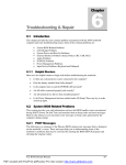
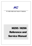
Chapter Hardware Functional Overview 4.1 Overview The FIC M785 notebook consists of several important functions and subsystems including: • System Processor – implemented on the motherboard using the Intel uFCPGA DT Pentium 4 Northwood at 400/533 MHz Front System Bus speed. • System North Bridge Core Logic – implemented on the motherboard using the SIS 650 chipset. • - CPU Interface - AGP BUS Controller - DDR DRAM Controller - MuTIOL Media I/O System South Bridge Core Logic – implemented on the motherboard using the SIS 962 chipset. - Integrated MuTIOL Connect to PCI Bridge - Dual IDE Master/Slave Controller, Integrated DMA • Clock Frequency Generator – implemented on the motherboard using the ICS 952001 clock generator chip. • Cache Memory Subsystem – implemented on-die on the Intel CPU. - L1 cache (Pentium Processor Internal) - - • • - 256KB Advanced Transfer Cache,8 way associativity - 8-way set associative, 32-byte line size, 1 line per sector - High Performance and high quality 3D accelerator - Integrated VB bridge - High performance 2D accelerator - Complete TV-OUT/Digital Flat Panel Solution VRAM – embedded in SIS 650 Share system memory from 8MB up to 64MB PCMCIA Subsystem – implemented on the motherboard using the ENE CB1410 PCI-CARDBUS BRIDGE controller chip. - • L2 cache (Pentium Processor Internal) Video Subsystem – embedded in SIS 650 • 12KB code and 8KB data, which implemented 8 way set associative and write back Support Type II x2 (without door) Sound – implemented or integrated in south bridge (SIS 962) - AC’97 CODEC - Realtek ALC201 FIC M785 Service Manual PDF created with FinePrint pdfFactory Pro trial version http://www.pdffactory.com 4-1 Hardware Functional Overview • AC’97 Revision 2.1 Compliant USB and Bluetooth – implemented or integrated in south bridge (SIS 962) - USB v2.0 and Intel Universal HCI v.1.1 Compatible - Eighteen level (doublewords) data FIFO with full scatter and gather capability - Root hub and four function ports - Integrated physical layer transceivers with optional over-current detection status on USB inputs - Legacy keyboard and PS/2 mouse support • Keyboard and Pointing Device Subsystem – implemented on the motherboard using the Keyboard assembly, and the Glidepad assembly. • I/O Subsystem – implement included on the SIS 962. • RTC + NVRAM – integrated in south bridge (SIS 962) - • Real Time Clock with 256 byte extend CMOS IBM AT Clock/ Calendar/ Alarm (14 Bytes) Internal Modem /LAN - MDC Modem - V.90, K56flex, ITU-T V.34, V.32, RJ11 Jack - TIA/EIA 602, V.42 ITU-T V.17, V.29, V.27ter, V.21 Ch2 - TIA/EIA 578 Class1 FAX - Wake up on Ring - 4-2 LAN (ICS) - Support for auto-negotiation (10BASE-T and 100BASE-TX) - Wake up On LAN • Power Subsystem – implemented on the motherboard, LCD Inverter Board, Battery Pack, and AC adapter. • Micro-P Subsystem – embedded controller on the motherboard using Mitsubishi PMU08 FIC M785 Service Manual PDF created with FinePrint pdfFactory Pro trial version http://www.pdffactory.com Hardware Functional Overview 4.2 System Hardware Block Diagram Figure 4-1 M785 Diagram FIC M785 Service Manual PDF created with FinePrint pdfFactory Pro trial version http://www.pdffactory.com 4-3 Hardware Functional Overview 4.3 Chipset Summary The M785 notebook consists of following major chipsets: Controller Chip Processor Core Logic Video Controller PCMCIA Controller Supper I/O Controller Audio Chip Sound Codec Chip Keyboard Controller PMU Controller Gas Gauge IC ROM BIOS Vendor Intel SIS Embedded in SIS 650 ENE SMSC Embedded in SIS 962 Realtek EME Mitsubishi Description uFCPGA Northwood DT Pentium 4 2.0/2.2/2.26/2.4/2.53 GHz (Desktop, FSB 400/533 MHz) Pentium 4: Integrated 256KB L2 Cache SIS 650 + SIS 962 Integrated VGA Core with shared 16/32/64MB memory CB1410 PCI-CARDBUS Bridge LPC47N267 Integrated in South Bridge (SIS 962) ALC201 KB38867 PMU08, Mitsubishi M38859FFHP Included in PMU08 SST 49LF040A Clock Generator Temperature Sensor ICS NS ICS952001 MAX1617 Modem NDC AC97 Interface LAN Bluetooth IEEE1394 ICS ICS 1893AF None Fw 801 4.4 AGERE System Processor (CPU) The FIC M785 runs on Intel Pentium 4 based on uFCPGA packaging. It supports CPU with up to 2.53GHz clock speed rating. The processor operates in conjunction with the RAM and ROM memory and the system control logic (e.g. SIS 650) to process software instructions (BIOS, Windows, and Applications). 4.4.1 Intel DT Pentium 4 Product Highlights 4-4 • The Pentium 4 processor is available at speeds ranging from 2.0 GHz to 2.80 GHz • 533-MHz system bus available with speeds at 2.26, 2.40B, 2.53, 2.66 and 2.80 GHz. 400-MHz system bus available with speeds at 1.70, 1.80, 1.80A, 1.90, 2A, 2.20, 2.40, 2.50 and 2.60 GHz. • 512-KB L2 Advanced Transfer Cache available with speeds from 1.80A GHz to 2.80 GHz. 256-KB L2 Advanced Transfer Cache available with speeds 1.70 GHz to 1.90 GHz. • The Pentium 4 processor is available in the mPGA-478 form factor • Featuring the Intel NetBurst microarchitecture FIC M785 Service Manual PDF created with FinePrint pdfFactory Pro trial version http://www.pdffactory.com Hardware Functional Overview • Supported by the Intel® 850 and Intel® 845 chipset families • Compatible with existing Intel® Architecture-based software • Streaming SIMD Extensions 2 (SSE2) Instructions • Intel® MMX™ media enhancement technology • Integrated caches include 12-K micro-op trace cache and 8-KB L1 data cache in addition to L2 cache memory • Support for uni-processor designs • Based upon Intel's leading 0.13 micron and 0.18 micron manufacturing process technologies. 0.13 micron process with speeds from 1.80A GHz to 2.80 GHz and 0.18 micron process with speeds 1.70 GHz to 1.90 GHz. Intel’s Most Advanced, Most Powerful Processor for Desktop PCs and Entry Level Workstations The Pentium 4 processor at 1.70, 1.80, 1.80A, 1.90, 2A, 2.20, 2.26, 2.40, 2.40B, 2.50, 2.53, 2.60, 2.66 and 2.80 GHz is designed for desktop PCs, as well as for entry-level workstations. The processor is binary-compatible with previous generation Intel Architecture processors. Intel® NetBurst™ Microarchitecture Intel NetBurst microarchitecture delivers a number of innovative features including hyperpipelined technology, 533-MHz or 400-MHz system bus, Execution Trace Cache, and Rapid Execution Engine, as well as a number of enhanced features such as Advanced Transfer Cache, Advanced Dynamic Execution, enhanced floating-point and multimedia unit, and Streaming SIMD Extensions 2 (SSE2). Many of these innovations and advances were made possible with improvements in processor technology, process technology, and circuit design and could not previously be implemented in high-volume, manufacturable solutions. The features and resulting benefits of the microarchitecture are defined below. Hyper-Pipelined Technology The hyper-pipelined technology of the Intel NetBurst microarchitecture doubles the pipeline depth compared to the P6 microarchitecture used on today's Pentium III processors. One of the key pipelines, the branch prediction / recovery pipeline, is implemented in 20 stages in the Intel NetBurst microarchitecture, compared to 10 stages in the P6 microarchitecture. This technology significantly increases the performance, frequency, and scalability of the processor. 533-MHz or 400-MHz System Bus The Pentium 4 processor's 533-MHz system bus supports Intel's highest performance desktop processor by delivering 4.2 GB of data-per-second into and out of the processor. This is accomplished through a physical signaling scheme of quad pumping the data transfers over a 133-MHz clocked system bus and a buffering scheme allowing for sustained 533-MHz data transfers. The Pentium 4 processor's 400-MHz system bus supports Intel's performance desktop processor by delivering 3.2 GB of data-per-second into and out of the processor. This is accomplished through a physical signaling scheme of quad pumping the data transfers over a 100-MHz clocked system bus and a buffering scheme allowing for sustained 400-MHz data transfers. This compares to 1.06 GB/s delivered on the Pentium III processor's 133-MHz system bus. FIC M785 Service Manual PDF created with FinePrint pdfFactory Pro trial version http://www.pdffactory.com 4-5 Hardware Functional Overview Level 1 Execution Trace Cache In addition to the 8-KB data cache, the Pentium 4 processor includes an Execution Trace Cache that stores up to 12-K decoded micro-ops in the order of program execution. This increases performance by removing the decoder from the main execution loop and makes more efficient usage of the cache storage space since instructions that are branched around are not stored. The result is a means to deliver a high volume of instructions to the processor's execution units and a reduction in the overall time required to recover from branches that have been mis-predicted. Rapid Execution Engine Two Arithmetic Logic Units (ALUs) on the Pentium 4 processor are clocked at twice the core processor frequency. This allows basic integer instructions such as Add, Subtract, Logical AND, Logical OR, etc. to execute in one-half a clock cycle. For example, the Rapid Execution Engine on a 2.80 GHz Pentium 4 processor runs at 5.60 GHz. 512-KB or 256-KB, Level 2 Advanced Transfer Cache 512-KB L2 Advanced Transfer Cache (ATC) is available with speeds 1.80A, 2A, 2.20, 2.26, 2.40, 2.50, 2.53, 2.60, 2.66 and 2.80 GHz. 256-KB L2 ATC is available with speeds 1.70 GHz to 1.90 GHz. The Level 2 ATC delivers a much higher data throughput channel between the Level 2 cache and the processor core. The Advanced Transfer Cache consists of a 256-bit (32-byte) interface that transfers data on each core clock. As a result, the Pentium 4 processor at 2.80 GHz can deliver a data transfer rate of 89.6 GB/s. This compares to a transfer rate of 16 GB/s on the Pentium III processor at 1 GHz. Features of the ATC include: • Non-Blocking, full speed, on-die level 2 cache • 8-way set associativity • 256-bit data bus to the level 2 cache • Data clocked into and out of the cache every clock cycle Advanced Dynamic Execution The Advance Dynamic Execution engine is a very deep, out-of-order speculative execution engine that keeps the execution units executing instructions. The Pentium 4 processor can also view 126 instructions in flight and handle up to 48 loads and 24 stores in the pipeline. It also includes an enhanced branch prediction algorithm that has the net effect of reducing the number of branch mis-predictions by about 33% over the P6 generation processor's branch prediction capability. It does this by implementing a 4-KB branch target buffer that stores more detail on the history of past branches, as well as by implementing a more advanced branch prediction algorithm. Enhanced Floating-Point and Multimedia Unit The Pentium 4 processor expands the floating-point registers to a full 128-bit and adds an additional register for data movement which improves performance on both floating-point and multimedia applications. 4-6 FIC M785 Service Manual PDF created with FinePrint pdfFactory Pro trial version http://www.pdffactory.com Hardware Functional Overview Streaming SIMD Extensions 2 (SSE2) Instructions With the introduction of SSE2, the Intel NetBurst microarchitecture now extends the SIMD capabilities that MMX technology and SSE technology delivered by adding 144 instructions. These instructions include 128-bit SIMD integer arithmetic and 128-bit SIMD double-precision floating-point operations. These instructions reduce the overall number of instructions required to execute a particular program task and as a result can contribute to an overall performance increase. They accelerate a broad range of applications, including video, speech, and image, photo processing, encryption, financial, engineering and scientific applications. Data Prefetch Logic Functionality that anticipates the data needed by an application and pre-loads it into the Advanced Transfer Cache, further increasing processor and application performance. Features Used for Testing and Performance / Thermal Monitoring • Built-in Self Test (BIST) provides single stuck-at fault coverage of the microcode and large logic arrays, as well as testing of the instruction cache, data cache, Translation Lookaside Buffers (TLBs), and ROMs. • IEEE 1149.1 Standard Test Access Port and Boundary Scan mechanism enables testing of the Pentium 4 processor and system connections through a standard interface. • Internal performance counters for performance monitoring and event counting. • Includes a Thermal Monitor feature that allows motherboards to be cost effectively designed to expected application power usages rather than theoretical maximums. 4.5 System Core Logic The system core logic function of the notebook is implemented on the CPU module and motherboard using the SiS650 IGUI HMAC. SiS650 IGUI Host Memory Controller integrates a high performance host interface for Intel Pentium 4 processor, a high performance 2D/3D Graphic Engine, a high performance memory controller, an AGP 4X interface, and SiS MuTIOL Technology connecting w/ SiS962 MuTIOL Media IO. SiS650 Host Interface features the AGTL & AGTL+ compliant bus driver technology with integrated on-die termination to support Intel Pentium 4 processors. SiS650 provides a 12-level InOrder-Queue to support maximum outstanding transactions up to 12. It integrated a high performance 2D/3D Graphic Engine, Video Accelerator and Advanced Hardware Acceleration MPEGI/MPEGII Video Decoder for the Intel Pentium 4 series based PC systems. It also integrates a high performance 2.1GB/s DDR266 Memory controller to sustain t he bandwidth demand from t he integrated GUI or external AGP master, host processor, as well as the multi I/O masters. In addition to integrated GUI, SiS650 also can support external AGP slot with AGP 1X/2X/4X capability and Fast Write Transactions. A high bandwidth and mat ure SiS MuTIOL technology is incorporated to connect SiS650 and SiS962 MuTIOL Media I/O together. SiS MuTIOL technology is developed into three layers, the Multi-t hreaded I/O Link Layer delivering 1.2GB bandwidth to connect embedded DMA Master devices and external PCI masters to interface to Multi-threaded I/O Link layer, the Multi-t hreaded I/O Link Encoder/Decoder in SiS962 to transfer data w/ 533 MB/s bandwidt h from/to Multi-threaded I/O Link layer to/from SiS650, and the Multi-t hreaded I/O Link FIC M785 Service Manual PDF created with FinePrint pdfFactory Pro trial version http://www.pdffactory.com 4-7 Hardware Functional Overview Encoder/Decoder in SiS650 to transfer data w/ 533 MB/s from/to Multi-threaded I/O Link layer to/from SiS962 An Unified Memory Controller supporting DDR200/266 DRAM is incorporated, delivering a high performance data transfer to/from memory subsystem from/to the Host processor, the integrated graphic engine or external AGP master, or the I/O bus masters. The memory controller also supports the Suspend to RAM function by retaining the CKE# pins asserted in ACPI S3 state in which only AUX source deliver power. The SiS650 adopts the Shared Memory Architecture, eliminating the need and thus the cost of the frame buffer memory by organizing the frame buffer in the system memory. The frame buffer size can be allocated from 8MB to 64MB. 4.5.1 SiS650 IGUI HMAC 3D Graphic Chipset Features The SiS650 chipset is ideal for the high performance, high quality, high energy efficient and high integration notebook AGP / PCI / ISA computer systems. The Integrated GUI features a high performance 3D accelerator with 2 Pixel / 4 Text ure, and a 128 bit 2D accelerator with 1T pipeline BITBLT engine. It also features a Video Accelerator and advanced hardware acceleration logic to deliver high quality DVD playback. A Dual 12 bit DDR digital video link interfaced to SiS 301B Video Bridge packaged in 100-pin PQFP is incorporated to expand the SiS 650 functionality to support the secondary display, in addition to the default primary CRT display. The SiS 301B Video Bridge integrates an NTSL/PAL video encoder with Macro Vision Ver. 7.1.L1 option for TV display, a TMDS transmitter with Bi-linear scaling capability for TFT LCD panel support, and an analog RGB port to support a secondary CRT. The primary CRT display and the extended secondary display (TV, TFT LCD Panel, 2'nd CRT) features the Dual View Capability in the sense that both can generate the display in independent resolutions, color depths, and frame rates. The SiS650 functions and capabilities include: High Performance Host Interface • • • • • • • • • Support Intel Pentium 4 series CPU with data transfer rate of 400/533MHz. Support 12 Outstanding Transactions Synchronous/Asynchronous Host-t-DRAM Timing Master deliver System Bus Interrupt support Smart Prefetch mechanism to boost memory read performance Support 2M/4M/8M/16M TSEG SMRAM Support Defer function to maxi mi ze bus utilization Support Dynamic Bus Inversion AGTL+ & AGTL compliant bus driver auto compensation 64 Bit High Performance DDR266/PC133 Memory Controller • • • • • 4-8 Supports DDR266/200 SDRAM or PC133/100 SDRAM Support Up to 3 un-buffer Double-sided DIMM DDR266/200 Up to 1 GB per DIMM with max. memory size up to 1 GB Supports 128Mb, 256Mb, & 512Mb SDRAM technology with page size from 2KB up to 16 KB Sustains DDR SDRAM CAS Latency at options of 2, 2.5, & 3 clocks FIC M785 Service Manual PDF created with FinePrint pdfFactory Pro trial version http://www.pdffactory.com Hardware Functional Overview • • • • • Programmable buffer strength optimi zing performance and stability Dynamic Clock Enable(CKE) control placing the SDRAM into Suspend to DRAM state High performance unified memory controller optimi zing the DRAM bus utilization Programmable frame buffer size from 8MB and up to 64MB 128KB SMRAM space re-mapping to A0000h, B0000h, or E0000h Integrated A.G.P. Compliant Target/66Mhz Host-to-PCI Bridge • • • • • • • AGP v2.0 Compliant Supports Graphic Window Size from 4MBytes to 256Mbytes Supports Pipelined Process in CPU-to- A.G.P. Access Supports 8 Way, 16 Entries Page Table Cache for GART to Enhance A.G.P. Controller Read/Write Performance Supports PCI-to-PCI Bridge Function for Memory Write from 33Mhz PCI Bus to A.G.P. device Supports Additional AGP4X/2X interface and Fast Write Transaction High Throughput SiS MuTIOL connect to SiS962 MuTIOL Media I/O • Bi-directional 16 bit data bus • Perform 533MB/s bandwidth in 66MHz x 4 mode • Distributed arbitration strategy with enhanced mode of contiguous DMA data Streaming • Packet based, pipelining, and split transaction scheme High Performance & High Quality 3D Accelerator • Built-in a high performance 256-bit 3D engine − Built-in 32-bit floating point format VLIW triangle setup engine − Built-in 2 pixel rendering pipelines and 4 texture units − Built-in hardware stereo auto rendering engine − Supports Ultra-AGPIITM with 2GB/s bandwidth − Up to 143 MHz 3D engine clock speed − Peak polygon rate: 10M polygon/sec @ 1 pixel/polygon with Gouraud shaded, point-sampled, linear and bilinear texture mapping − Peak fill rate: 286 M pixel/sec, 572 M texture/sec @ 10,000 pixel/polygon with Gouraud shaded and two bilinear textured, Z buffered and alpha blended • Built-in a high quality 3D engine − Supports flat, and Gouraud shading − Supports high quality dithering − Supports Z-test, stencil test, Alpha-test, and scissors clipping test − Supports 16 ROPs − Supports Z-buffer, stencil buffer − Supports 16/24/32 bits integer Z buffer format and 32 bits floating point Z format − Supports 16/32 BPP render buffer format − Supports 1/2/4/8 stencil buffer format − Supports per-pixel texture perspective correction − Supports point-sampled, linear, bi-linear, and dual bi-linear texture filtering − Supports up to 2 pixels with 4 bi-linear texels within single cycles − Supports up to 2048x2048 texture size FIC M785 Service Manual PDF created with FinePrint pdfFactory Pro trial version http://www.pdffactory.com 4-9 Hardware Functional Overview − − − − − − − − − − Supports rectangle structure texture Supports 16/24/32 bpp RGB/ARGB texture format Supports DTX1, DTX2, DTX3 texture compression formats Supports texture transparency, blending, wrapping, mirror, and clamping Supports fogging, alpha blending Supports vertex fogging and fog table Supports specular lighting Supports 2X/4X multi-sampling full scene anti-aliasing Supports back face culling Supports auto-stereo rendering High Performance 2D Accelerator • • • • • • • • Built-in 128 double-words hardware command queue Built-in Direct Draw Accelerator Built-in GDI+ Accelerator Built-in an 1T pipelined 128-bit BITBLT graphics engine with the following functions: − 256 raster operations − Rectangle fill − Trapezoid fill − Color expansion (by 384 patterns registers) − Enhanced color expansion − Line-drawing with styled pattern − NT fractional point line-drawing with styled pattern − Multiple scan line − Built-in 256 bytes pattern registers − Built-in 8x8 mask registers − Rectangle clipping − Transparent BitBlt with source and destination keys (16 ROPs) − Gradient color fill − Anti-aliasing text drawing − Alpha blended Bitblt Supports memory-mapped, zero wait-state, burst engine write Built-in 64x64x2 bit-mapped mono hardware cursor Built-in 64x64x16 bit-mapped blended color hardware cursor Maximum 64MB frame buffer with linear addressing Complete TV-OUT/Digital Flat Panel Solution • • • • • Built-in secondary CRT controller for independent secondary CRT, LCD or TV digital Output Cooperates with “SIS650 Video Bridge” to support NTSC/PAL Video Output Digital LCD Monitor Secondary CRT Monitor Supports Dual 12-bit DDR digital interface to TV encoder and LCD transmitter High Integration • Built-in 64x128 CRT FIFOs to support ultra high resolution graphics modes and reduce 4-10 FIC M785 Service Manual PDF created with FinePrint pdfFactory Pro trial version http://www.pdffactory.com Hardware Functional Overview • • • • CPU wait-state Built-in programmable 24-bit true-color RAMDAC up to 333 MHz pixel clock − Built-in reference voltage generator and monitor sense circuit − Supports downloadable 24 bits RAMDAC for gamma correction in high color and true color modes − Support programmable 4 levels DAC current ratio (700, 750, 800, 850 mv) − Support programmable pedestal level (0, 0.75mv) − Support programmable 4 levels slew rate control Built-in two clock generators − Integrates PLL loop filter for CRT, 2D, 3D, MPEG and VP Engine Built-in two 120x128 video line buffers for MPEG II video playback Built-in TV Encoder Interface Power Management • • • • • • • Supports VESA Display Power Management Signaling (DPMS) compliant VGA monitor for power management Supports direct I/O command to force graphics controller into standby/suspend/off state Power down internal Gamma/Palette SRAM in direct color mode Supports PCI power management configuration registers for supporting ACPI power down controller Power down all internal macro cells such as SRAM, DAC, clock generator when power saving mode Supports clock stopping for video accelerator, VP, 2D, 3D and MPEG decoder when disabled Supports auto clock throttling for 2D engine, 3D engine 4.5.2 SiS 962 MuTIOL Media I/O Features The SiS962 MuTIOL Media I/O integrates the Audio Controller with AC 97 Interface, the Ethernet MAC, the Dual Universal Serial Bus Host Controllers, the IDE Master/Slave controllers, and the MuTIOL Connect to PCI bridge. The PCI to LPC bridge, I/O Advanced Programmable Interrupt Controller, legacy system I/O, I/O Advanced Programmable Interrupt Controller and legacy power management functionalities are also integrated. The Integrated Audio Controller features a 6 channels of AC 97 v2.2 compliance audio to present 5.1-channel Dolby digital material or to generate stereo audio with simultaneous V.90 HSP modem operation. Besides, 4 separate SDATAIN pins are provided to support multiple audio Codecs + one modem Codec maxi mally, effectuating the realization of 5.1 channel Dolby digital material in theater quality sound. Both traditional consumer digital audio channel as well as the AC 97 v2.2 compliant consumer digital audio slot are supported. VRA mode is also associated with both the AC 97 audio link and the traditional consumer digital audio channel. The integrated Fast Ethernet MAC features an IEEE 802.3 and IEEE 802.3x compliant MAC supporting full duplex 10 Base-T, 100 Base-T Ethernet, or 1Mb/s & 10Mb/s Home networking. 5 wake-up Frames, Magic Packet and link status change wake-up functions in G1/G2 states are supported. Besides, the integrated MAC provides a scheme to store the MAC address without the need of an external EEPROM. The 25 MHz oscillating circuit is integrated so as only an external low cost 25 MHz crystal is needed for the clocking system. FIC M785 Service Manual PDF created with FinePrint pdfFactory Pro trial version http://www.pdffactory.com 4-11 Hardware Functional Overview The integrated Universal Serial Bus Host Controllers features Dual Independent OHCI Compliant Host controllers with six USB ports delivering 2 x 12 Mb/s bandwidth and rich connectivity. Besides, each port can be optionally configured as the wake-up source. Legacy USB devices as well as over current detection are also implemented. The integrated IDE Master/Slave controllers features Dual Independent IDE channels supporting PIO mode 0,1,2,3,4, and Ultra DMA 66/100/133. It provides two separate data paths for the dual IDE channels that sustain the high data transfer rate in the multitasking environment. The MuTIOL Connect to PCI bridge supporting 6 PCI master is compliant to PCI 2.2 specification. The SiS962 also incorporates the legacy system I/O like: two 8237A compatible DMA controllers, three 8254 compatible programmable 16-bit counters, hardwired keyboard controller and PS2 mouse interface, Real Time clock with 256B CMOS SRAM and two 8259A compatible Interrupt controllers. Besides, the I/O APIC managing up to 24 interrupts with both Serial and FSB interrupt delivery modes is supported. The integrated power management module incorporates the ACPI 1.0b compliance functions, the APM 1.2 compliance functions, and the PCI bus power management interface spec. v1.1. Numerous power-up events and power down events are also supported. 21 general purposed I/O pins are provided to give an easy to use logic for specific application. In addition, the SiS962 supports Intel Speed Step technology and Deeper Sleep power state for Intel Mobile processor. The SiS 962 MuTIOL Media I/O functions and capabilities include: High performance MuTIOL Connect Interconnecting SiS’s Series NBs • • • • Bi-directional 16-bit data bus at 266MHZ operating Frequency 533MB/s performance in 4x66 MHz mode Distributed Arbitration Scheme Supports Back to Back Transaction Integrated Multi-threaded I/O link ensures concurrency of upstream/down stream data transfer Multiple DMA Bus Architecture • • • • Concurrent Servicing of all DMA Devices: Dual IDE Controllers, Dual USB HCs, MAC Controller, and Audio/Modem DMA Controller Separate 32 Bit Input and Output Data Bus Scheme for each DMA Device Advanced Performance Merits of Split & Pipelined Transaction and Concurrent Execution among Multi-I/O Devices Integrated MuTIOL Connect to PCI Bridge • • • • • PCI 2.2 Specification Compliance Supports up to 6 PCI Masters Two Prefetch cache Buffers support 2 delayed transactions Fairness Rotating PCI Arbiter Scheme with Option to Place PCI Master 0 as the Highest Priority Write Promotion Mechanism to Guarantee the 10 µs Time Limit of PCI Memory Write 4-12 FIC M785 Service Manual PDF created with FinePrint pdfFactory Pro trial version http://www.pdffactory.com Hardware Functional Overview Dual IDE Master/Slave Controller • • • • • Integrated Multithreaded I/O Link Mastering with Read Pipelined Streaming Dual Independent IDE Channels Each with 16 DW FIFO Native and Compatibility Mode PIO Mode 0, 1, 2, 3, 4 and Multiword DMA Mode 0, 1, 2 Ultra DMA 66/100/133 Universal Serial Bus Host Controller • • • • • • Integrated Multithreaded IO Link Mastering Dual Independent OHCI Controllers with Root Hub Supports up to 6 USB 2.0/1.1 Ports Supports Legacy Devices Over Current detection Equipped Option to Separately Configure Each Port as a Wake-up Source Integrated Audio Controller with AC97 Interface • • • • • • • AC97 v2.2 compliance 6 Channels of AC97 Audio to Present 5.1-channel Dolby Digital Material (Found in DVD Movies) or to Generate Stereo Audio with V9.0 HSP-Modem Operation 4 Separate SDATAIN pins supporting multiple Audio Codecs and one Modem Codec Effectuating the Realization of 5.1 Channel Dolby Digital Material in Theater Quality Sound Supports Audio and Modem function with Multithreaded I/O link mastering Supports two Consumer Audio Digital interface: traditional Consumer Digital Audio Out and AC97 V2.2 Compliance Consumer Audio Digital Interface Supports VRA Mode for both AC97 Audio Link and Consumer Audio Digital Interface Advanced Power Management • • • • • • • • • • • • Meets ACPI 1.0b Requirements Meets APM 1.2 Requirements ACPI Sleep States Include S1, S3, S4, S5 CPU Power States Include C0, C1, C2 C3 Supports Intel Speed Step Technology and Deeper Sleep power state for Intel mobile processor Power Button with Override RTC Day-of-Month, Month-of-Year Alarm 24-bit Power Management Timer LED Blinking in S0, S1 and S3 States Software Watchdog Timer Power Supply’98 Support PCI Bus Power Management Interface Spec. 1.1 Integrated Keyboard Controller • • Hardwired Logic Provides Instant Response Supports PS/2 Mouse Interface FIC M785 Service Manual PDF created with FinePrint pdfFactory Pro trial version http://www.pdffactory.com 4-13 Hardware Functional Overview • • • Password Security and Password Power-Up System Sleep and Power-Up by Hot-Key KBC and PS2 Mouse Can Be Individually Disabled Integrated PCI to LPC Bridge • LPC 1.0 Compliance Integrated Real Time Clock (RTC) with 256B CMOS SRAM • • • Supports ACPI Day-of-Month and Month-of-Year Alarm 256 Bytes of CMOS SRAM Provides RTC H/W Year 2000 Solution 4.6 Clock Frequency Generator The notebook utilizes the ICS 952001 chip to supply the system clock needed to run the computer. The following are the available clock frequencies: System clock: Clock generator ICS 952001 support: - 66/100 MHz for Pentium Mobile CPU - 30/33 MHz for PCI device bus clock use - 48 MHz for PIIX4M - 14.318 MHz for PIIX4M refresh use • 14.318 MHz XTAL for Clock Generator use • 32.768 KHz XTAL for RTC real time clock • 8.0 MHz XTAL for K/B controller use • 14.318 MHz OSC for sound blaster use 4.7 Cache Memory The primary (L1) and secondary (L2) level cache are integrated on the CPU. By incorporating the cache on-die (meaning it is combined with the CPU into one component), Intel eliminates the need for separate components. The 512KB on-die L2 cache provides three (3X) times faster processor access, resulting in significant improvements in performance. Likewise, an integrated cache means a reduction of connections resulting in increased reliability. 4.8 System Memory The memory subsystem, implemented on the motherboard, includes System and Video memory. The SIS 650 System Controller chip provides primary control for the system memory. 4.8.1 System Memory The notebook offers two 64-bit SODIMM (Small Outline Dual Inline Memory Module) sockets for main memory configuration. The memory sockets accept any standard 144-pin SODIMM modules at 128MB, 256MB and 512MB sizes. Memory modules are 2.5V DDR SDRAM type. 4-14 FIC M785 Service Manual PDF created with FinePrint pdfFactory Pro trial version http://www.pdffactory.com Hardware Functional Overview 4.8.2 Video Memory The video memory of the notebook is embedded inside the VGA controller chip (SIS 650) with 16,32 and 64MB SMA video memory that can support display resolutions of up to 1024 x 768 at 32-bit 16M color (TFT LCD). 4.9 System BIOS The notebook utilizes the Phoenix BIOS 4.0 Release 6.0 (Basic I/O System) that contains both the main system BIOS and the VGA BIOS with Shadow BIOS capability. It utilizes Flash EPROM BIOS that allows instant erasing and programming without replacing the EPROM chip. The BIOS is stored in a 32-pin PLCC package FLASH ROM SST 49LF040A with 4Mbit size and is mounted into the motherboard. While posting the system, the Shadow RAM will be enabled and the ROM will be disabled. 4.10 Video Subsystem The video subsystem, embedded inside the North Bridge chip and the LCD panel, controls the display output to both the LCD Panel screen and to the external VGA port. 4.10.1 Video Chip Controller The SIS 650 chipset includes the shared architecture memory of 16/32/64 Mb. Features summary of the SIS 650 Video Chip Controller: Resolution, Color & Frame Rate • Supports 333 MHz pixel clock • Supports VESA standard super high resolution graphics modes − 640x480 16/256/32K/64K/16M colors 85 Hz NI − 800x600 16/256/32K/64K/16M colors 85 Hz NI − 1024x768 256/32K/64K/16M colors 85 Hz NI − 1280x1024 256/32K/64K/16M colors 85 Hz NI − 1600x1200 256/32K/64K/16M colors 85Hz NI − 1920x1440 256/32K/64K/16M colors 85Hz NI − 2048x1536 256/32K/64K/16M colors 75Hz NI − Low resolution modes − Supports virtual screen up to 4096x4096 (320x240, 512x384, 400x300) Video Accelerator • Supports single frame buffer architecture • Supports single video windows with overlay function • Supports YUV-to-RGB color space conversion • Supports bi-linear video interpolation with integer increments of 1/2048 • Supports graphics and video overlay function − Independent graphics and video formats − 16 color-key and/or chroma-key operations FIC M785 Service Manual PDF created with FinePrint pdfFactory Pro trial version http://www.pdffactory.com 4-15 Hardware Functional Overview • • • • • • • • − Support YUV or RGB format chroma key − Rectangular video window mode − Video only mode − VCD, DVD and up to HDTV playback mode − Supports reading-back of current refresh scan line − Supports tearing free double buffer flipping Supports RGB555, RGB565, YUV422, and YUV420 video playback format Supports filtered horizontal up and down scaling playback Supports DVD sub-picture playback overlay Supports DVD playback auto-flipping Built-in two 120x128 video playback line buffers to support 1920x1080 video playback Built-in independent Gamma correction RAM Supports DCI Drivers Supports Direct Draw Drivers 4.10.2 Video Clock SIS 650 North Bridge provides input to generate VGA internal slate machine, MCLK, and DCLK. Also provides 32.768 KHz O/P for video RAM refresh. 4.11 PCMCIA Controller The PCMCIA controller of the notebook is implemented on the motherboard using the ENE CB1410 CardBus Controller. The M785 notebook only supports single PCMCIA slot for PCICardbus Bridge. CARDBUS CONTROLLERS The CB1410 is an ACPI and PC98/99 logo certified high performance, single slot PC Card controller with a synchronous 32-bit bus master/target PCI interface. This PC Card to PCI bridge host controller is compliant with the 2000 PC Card Standard. This standard incorporates the new 32-bit CardBus while retaining the 16-bit PC Card specification as defined by PCMCIA release 2.1. CardBus is intended to support "temporal" add-in functions on PC Cards, such as Memory cards, Network interfaces, FAX/Modems and other wireless communication cards, etc. The high performance and capability of the CardBus interface will enable the new development of many new functions and applications. The CB1410 CardBus controller is compliant with the latest ACPI-PCI Bus Power Management interface Specification. It supports all four power states and the PME# function for maximum power savings and ACPI compliance. Additional compliance to On Now Power Management includes D3 cold state support, paving the way for low sleep state power consumption and minimized resume times. To allow host software to reduce power consumption further, the CB1410 provides a power-down mode in which internal clock distribution and the PC Card socket clocks are stopped. An advanced CMOS process is also used to minimize system power consumption. The CB1410 single PCMCIA socket supports the 3.3V/5V 8/16-bit PC Card R2 cards or 32bit CardBus R3 cards. The R2 card support is compatible with the Intel 82365SL PCIC controller, and the R3 card support is fully compliant with the 2000 PC Card Standard CardBus specification. The CB1410 is an additional buffer chip for the PC Card socket interface. In addition, the CB1410 supports dynamic PC Card hot insertion and removal, with auto configuration capabilities. 4-16 FIC M785 Service Manual PDF created with FinePrint pdfFactory Pro trial version http://www.pdffactory.com Hardware Functional Overview The CB1410 is fully complains with the 33Mhz PCI Bus specification, v2.2. It supports a master device with internal CardBus direct data transfer. The CB1410 implements FIFO data buffer architecture between the PCI bus and CardBus socket interface to enhance data transfers to CardBus Devices. The bi-directional FIFO buffer permits the CB1410 to accept data from a target bus (PCI or CardBus interface) while simultaneously transferring data. This architecture not only speeds up data transfers but also prevents system deadlocks. The CB1410 is a PCMCIA R2/CardBus controller, providing the most advanced design flexibility for PC Cards that interface with advanced notebook designs. CB1410 FEATURES – only Single Slot Solution • Supports only one PCMCIA 2.1 and JEIDA 4.2 R2 cards or 2 CardBus cards • ACPI-PCI Bus Power Management Interface Specification Rev 1.1 Compliant • Supports OnNow LAN wakeup, OnNow Ring Indicate, PCI CLKRUN#, PME#, and CardBus CCLKRUN# • Compliant with the 33Mhz PCI Specification V2.2, 2000 PC Card Standard 7.1 for CB1410 • Yenta™ PCI to PCMCIA CardBus Bridge register compatible • ExCA (Exchangeable Card Architecture) compatible registers map-able in memory and I/O space • Intel™ 82365SL PCIC Register Compatible • Supports PCMCIA_ATA Specification • Supports 5V/3.3V PC and 3.3V Cardbus cards • Supports two PC Card or CardBus slots with hot insertion and removal • Supports multiple FIFOs for PCI/CardBus data transfer • Supports Direct Memory Access for PC/PCI and PCI/Way on PC Card socket • Programmable interrupt protocol: PCI, PCI+ISA, PCI/Way, or PC/PCI interrupt signaling modes • Win'98 IRQ and PC-98/99 compliant • Parallel or Serial interface for socket power control devices including Micrel and TI • Integrated PC 98/99 -Subsystem Vendor ID support, with auto lock bit • LED Activity Pins • CB1410 supports D3cold state PME# wakeup; 3.3Vaux Power; and Zoomed video buffer enable pins • CB1410: "Built-in" live video, high throughput, multimedia ZV ports support without FIC M785 Service Manual PDF created with FinePrint pdfFactory Pro trial version http://www.pdffactory.com 4-17 Hardware Functional Overview additional buffers; 3V card protection during host system suspend with Auto Card VS# resensing; dedicated ZV output port to LCD controller SmartCardBus™ (OZ711E1/OZ711E2) combines a Smart Card reader and CardBus controller in a single IC. In addition to meeting PC Card standards, SmartCardBus is compliant to Microsoft PC/SC, ISO 7816-1, -2, -3 electrical specifications, standard protocols including T = 0, T = 1, and synchronous and asynchronous formats. SmartCardBus lowers the cost of ownership of e-commerce and corporate security Smart Card applications. 4.12 Audio Subsystem The audio subsystem is integrated inside the South Bridge chip on the motherboard. Refer to the System Core Logic section of this chapter. An internal two-way mini speaker and microphone provide the notebook with mobile sound generation and recording capabilities. In addition, a set of 3.5mm bayonet socket (1/8” minijack) connectors allow for external microphone, line inputs, and headphone outputs. 4.13 Keyboard and Pointing Device The Keyboard Subsystem of the notebook is implemented on the Motherboard and Keyboard Assembly using the ENE KB3886 keyboard controller chip and the Phoenix MultiKey/M3886L keyboard controller firmware. This chip controls the internal built-in keyboard, the built-in touchpad pointing device, as well as the external PS/2 keyboard and mouse port. The keyboard controller allows simultaneous use of both the internal and external keyboard and PS/2 mouse. The M785 membrane keyboard is an 86-key IBM 101-key enhanced compatible keyboard with standard characters and 12 function keys including an embedded numeric keypad. See Chapter 1 for more information. The pointing device subsystem consists of the built-in Synaptics touch pad pointing device module on the system top cover assembly and a pre-programmed Mitsubishi 38869M8 microcontroller that interfaces the mouse device to the Motherboard. The touch pad module is connected to battery board through a 6-pin FPC cable. An external PS/2 port also supports the use of an external PS/2 compatible mouse where the system automatically detects on system power up and runs both internal and external mouse simultaneously. The Synaptic touch pad, a pointing device for personal computers, detects the position of a finger over a touch-sensitive area. To move the cursor, the user lightly slides a finger over the smooth sensor area. To ‘click’, the user gently taps on the surface. The ultra-thin module is the thinnest PCB based touchpad available today. It is a capacitive sensor - the finger is detected by measuring its effect on an array of capacitive lines integrated into the PC board. The pad senses both the finger’s position and its contact area (X, Y, and Z). The area of contact is a measure of applied pressure. One side of the module PC board is the sensor surface; electronic components are mounted on the other side. The sensitive area is protected by a layer of smooth and durable mylar. 4-18 FIC M785 Service Manual PDF created with FinePrint pdfFactory Pro trial version http://www.pdffactory.com Hardware Functional Overview The Synaptic touch pad communicates with the host via a standard PS/2 mouse or trackball interface. It is fully compatible with the standard Microsoft mouse driver. The module connector includes the PS/2 signal pins, power supply pins and two connections for external button switches. The Synaptic touch pad includes a special “edge-motion” feature that allows the user to extend a drag operation when the finger reaches the edge of the sensor pad. The cursor continues to coast in the indicated direction when the finger is held against the edge. 4.14 Disk Drives Subsystem The disk drives subsystem, implemented on the Motherboard and on the associated internal hard disk drive assembly and device bay, provides disk storage for all system software and user files. The notebook is equipped with high capacity hard disk drive using Enhanced IDE controller with LBA (Logical Block Addressing) and Ultra DMA mode support. The SIS 691 controller chip provides the Primary IDE controller for the internal hard disk, and the Secondary Master for the CD-ROM. The floppy disk drive supports standard 3.5-inch 720KB and 1.44MB mini-diskettes while adding support for 1.2MB (3 Mode) mini-diskettes for Japanese market. The notebook uses the 24X-speed IDE CD-ROM Drive that reads digital data stored on CDROM at 24 times faster rotational speed. The CD-ROM drive supports CD-DA transfer over ATAPI function that the host system can read CD audio data. The drive also supports PhotoCD Multi-session disc compatibility and Multimedia PC-3 specification compatibility. The notebook also could use the 8X+ speed IDE DVD-ROM Drive that reads DVD digital data stored on DVD-ROM at 8 times faster rotational speed. 4.15 Power Subsystem The Power Subsystem consists of the following major sections: 4.15.1 AC Power Adapter The computer is equipped with a 90W universal AC power adapter that converts AC voltage (100 to 240VAC, 50 to 60Hz) into DC voltage used to operate the notebook and charge the batteries. 4.15.2 Internal Battery Pack The computer utilizes Lithium-Ion (Li-Ion) that provides DC power for the notebook and real time clock battery on the motherboard when the AC Adapter is not connected to the computer. The normal charging time for the battery is around 2 hours when computer is turn off while it should take around 8 hours when the computer is running. Running time of battery is around 2 hours. FIC M785 Service Manual PDF created with FinePrint pdfFactory Pro trial version http://www.pdffactory.com 4-19 Hardware Functional Overview 4.15.3 DC-DC Module of Motherboard The DC-DC module receives approximately 12VDC from the battery pack and uses this input voltage to generate multiple regulated output voltages to provide power for all internal notebook board assemblies. 4.15.4 LCD Inverter Board Assembly The LCD Inverter Board Assembly is located in the LCD Panel Assembly. It converts the +12VDC input directly from the Battery Pack into a high voltage AC output used to light the CCFT (Cold-Cathode Fluorescent Tube). 4.16 Micro-P Subsystem (PMU-08) The micro controller Mitsubishi PMU08 acts as a supplement for the power management control. It supports many functions via the SMBus interface. The system communicates with the PMU08 via the SMBus interface. The SMBus host (M38869) should be first initialized before starting the transaction. The following is the procedure for system communication with PMU08: 1. 2. 3. 4. 5. 6. 7. 8. Enable SMBus interface by writing 01h to SmbHstCfg register. Get SMBus I/O port base address by reading from SmbBA register. Clear SMBus status by writing 1Eh to SmbHstSts register. Write the PMU07 slave address to SmbHstAdd register. − Send command to PMU08 -- Slave address is 04h. − Read data from PMU08 -- Slave address is 05h. Write the desired command to SmbHstCmd register. Write the desired parameters to SmbHstDat0 (High byte) and SmbHstDat1 (Low byte) registers if the system wants to send command to PMU08. Wait for SMBus interrupt occurred by monitoring SmbHstSts register INTR bit. Get the desired data by reading from SmbHstDat0 (High byte) and SmbHstDat1 (Low byte) registers if the system wants to read data from PMU08. Features Summary of the Micro-P: • • • • • • • • • • • • 4-20 5 channels 8-bit analog to digital converter Timer0: 8-bit tuner/counter with 8-bit prescaler Timer1: 16-bit timer/counter. TMR1 can be incremented during sleep via external crystal/clock Timer2: 8-bit timer/counter with 8-bit period register, prescaler and postscaler Capture, Compare, PWM module 2 Synchronous Serial port (SSP) with SPI and I C Universal Synchronous Asynchronous Receiver Transmitter (USART/SCI) Brown-out detection circuitry for Brown-out Reset (BOR) 2K bytes program memory 128 bytes data memory 22 I/O pin 8 interrupt sources FIC M785 Service Manual PDF created with FinePrint pdfFactory Pro trial version http://www.pdffactory.com