1
LIST Nos.
CS 33EA : E056 Mar.2009
CS 33ET : E055 Mar.2009
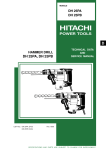
PRODUCT NAME
Hitachi Engine Chain Saw
Models
C
CS 33EA
CS 33ET
MARKETING OBJECTIVE
The new Models CS 33EA and CS 33ET engine chain saw are the minor-changed version of the current Models
CS 30EG and CS 35EJ. The new Models have suited EPA PHASE2, CARB Tier3 and 2004/26/EC.
In addition, the appearance is changed to the one for a next-generation model.
With the new Models CS 33EA and CS 33ET, we aim to enhance the share of the Hitachi engne chain saw
series.
APPLICATIONS
Sawing various types of lumber. Examples of application:
• Forestry: Lumbering and cutting off tree branches.
• Gardening: Cutting off tree branches, pruning and trimming.
• Home use: Cutting firewood, rough cutting in do-it-yourself carpentering.
• Leisure: Cutting firewood at camping sites.
• Farm: Cutting firewood, preparing lumber for cultivating mushrooms and cutting off tree branches.
• Carpentering: Rough cutting or cast-away cutting of pillars, back slitting, cutting used lumber and timber cutting.
• Civil engineering and construction: Cutting posts to equal length, cutting used lumber and timber cutting.
• Others: Rough cutting for large wood carvings.
.
SELLING POINTS
[ NEW FEATURES ]
New Pure Fire engine
Soft grip handle (The first in the industry)
Slide hook (CS33ET)
[Same features as the conventional models]
S-Start
Steering wheel shape by human engineering
The best balance
SPECIFICATIONS AND PARTS ARE SUBJECT TO CHANGE FOR IMPROVEMENT.
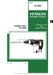
[CS33ET]
International Sales Division
REMARK:
• For more information about HANDLING INSTRUCTIONS, visit our website at:
http://www.hitachi-koki.com/manual_view_export/
• Throughout this TECHNICAL DATA AND SERVICE MANUAL, the symbols are used in the place of
company names and model names of our competitors. The symbols utilized here are as follows:
Competitors
Symbols Utilized
Company Name
Model Name
A
STIHL
MS192T
B
ECHO
CS-330T
C
Husqvana
235e
D
ECHO
CS-370
CONTENTS
Page
SELLING POINT DESCRIPTIONS ---------------------------------------------------------------------------------------- 1
SPECIFICATIONS ------------------------------------------------------------------------------------------------------------- 3
COMPARISONS WITH SIMILAR PRODUCTS ------------------------------------------------------------------------- 4
PRECAUTIONS IN SALES PROMOTION ------------------------------------------------------------------------------- 5
1. Instruction Manual ----------------------------------------------------------------------------------------------- 5
2. Caution Plate ----------------------------------------------------------------------------------------------------- 5
3. Through Instruction to the Customers ---------------------------------------------------------------------- 6
TROUBLESHOOTING GUIDE ---------------------------------------------------------------------------------------------- 7
REPAIR GUIDE ----------------------------------------------------------------------------------------------------------------- 8
1. Precautions on maintenance, inspection and repair ---------------------------------------------------- 8
2. Inspection criteria for each section and consumable parts -------------------------------------------- 8
Assembly diagram for CS 33EA
Assembly diagram for CS 33ET
SELLING POINT DESCRIPTIONS
New Pure Fire Engine
Equipped with the Pure Fire Engine, a clean emission engine compliant with the second emission
regulations specified in the U.S.A. and Europe (EPA PHASE2, CARB Tier3, 2004/26/EC).
(Note that emission values differ depending on countries and regions.)
Regulation value
g/kWh
CS33EA/ET
32.3mL
50 or less
50 or less
HC+Nox
(Unburnt material + nitrogen oxide)
Soft grip handle (The First in the industry)
Adopted the soft grip handle molded with elastomer in two layers for easy, non-slippery gripping, giving less
strain to the operator.
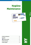
Slide hook (CS 33ET)
The hook used for hanging when the operator moves during elevated work can be housed inside the body
if unused, thereby improving workability.
Hook
Hook
When housed
When used
-1-
S-Start
The newly adopted coil damper type of recoil starter reduces the pulling force required for the starter by half
from our previous model, thereby simplifying starting operation. Moreover, the new throttle-linked choke
eliminates the bothersome step of having the operator return it to the original position as on the old choke.
Steering wheel shape by human engineering
The handle is indented to accommodate the operator’s thumb when gripped, thereby affording easier
gripping.
The best balance.
The chain saw’s center of gravity is optimally located for better balance and consequently better workability.
-2-
SPECIFICATIONS
Model
CS 33EA
CS 33ET
Engine type
Cylinder quantity
ʊ inner diameter x stroke
Engine displacement
Momentary no-load
revolutions
Air-cooled, two-cycle gasoline engine
Service revolutions
7,000 to 9,000 min-1
Idling revolutions
2,800 to 3,200 min-1
Rotation direction
Clockwise
Remarks
1-37 x 30 mm
32.3 mL
12,000 min-1
Revolutions at actual
work
When viewed from end
of the output shaft
Fuel tank capacity
Mixed gasoline
Gasoline: oil for two-cycle exclusive = (25 to 50):
1
30 mL (Continuously for 20 to 30 minutes)
Carburetor
Diaphragm type (from Walbro)
Spark plug
NGK BPM6A or BPMR6A
Starting method
Coil damper type recoil starter method
Air cleaning method
Dry
Stopping method
Ground
Muffler type
Power transmission
method
Guide bar length
Silencer
350 mm (14 inch), SN
300 mm (12 inch), SN
SN: Sprocket nose
Saw chain used
91VG-52
91VG-45
From Oregon
Saw chain
Pitch: 3/8 inch; gauge: 0.05 inch
Sprocket
Star, six teeth
Chain oil feeding method
Automatic feed
Chain oil tank capacity
190 mL
Service fuel
Automatic centrifugal clutch
Oil amount adjusting
type
Chain oil discharge rate
3 to 8 mL/minute (8,000 min-1)
Chain oil used
Dedicated chain oil
Handle
Equipped with anti-vibration device
Anti-vibration mechanism
Engine floating type
Dry weight
Overall dimensions
(L x W x H)
4.3 kg
4.1 kg
394 x 262 x 238 mm
279 x 264 x 225 mm
-3-
Standard opening
degree: 1-1/4 turns
back from totally
closed position
Excluding chain and
chain bar
COMPARISONS WITH SIMILAR PRODUCTS
Handle location
Top
Manufacturer/
Model
Item
Rear
HITACHI
HITACHI
A
B
CS 33ET
C
D
CS 33EA
Piston
displacement
mL
32.3
30.1
32.6
32.3
34.4
36.3
Maximum output
kW
1.2
1.2
1.2
1.2
1.3
–
Tank capacity
mL
300
270
310
300
300
410
Oil tank capacity
mL
190
220
290
190
190
280
Bar length
cm
(inch)
30, 35
30 - 40
30 - 40
30, 35
30 - 40
35 - 45
(12”)(14”)
(12”-16”)
(12”-16”)
(12”)(14”)
(12”-16”)
(14”-18”)
Chain pitch
Inch
3/8
3/8
3/8
3/8
3/8
3/8
–
Presented
None
None
Presented
None
None
50g/kWh
or less
EPA
Phase2
Not in
compliance
EPA
Phase2
EPA
Phase2
EPA
Phase2
Not in
compliance
–
Presented
None
Presented
Presented
Presented
Presented
kg
4.1
3.2
3.6
4.3
4.7
4.5
Soft grip
Emission standard
Device to reduce
pulling force
Body dry weight
(Excluding chain
and chain bar)
Overall L x W x H
mm
279 x 264 x 225 245 x 205 x 223 277 x 233 x 214 394 x 262 x 238
377 x 244 x 246 390 x 270 x 290
(Superior specifications:
-4-
)
PRECAUTIONS IN SALES PROMOTION
To ensure that customers safely and efficiently use the engine-powered chain saw after its purchase, urge
them to thoroughly read the instruction manual and understand the importance of the caution plates
described therein and attached to the product.
Tell the customers to refer to the instruction manual for how to properly handle, maintain, inspect and store
the product, with emphasis placed on periodic inspection.
Advise them to utilize our replenishment and repair systems for spare parts.
1. Instruction Manual
Each process of chain saw design, fabrication and inspection is subject to the utmost care to ensure safety
as a commercial product; however, an engine-powered chain saw is inherently dangerous. To protect
customers against such danger and ensure safe use of the engine-powered chain saw, the Instruction
Manual describes precautions on using the product. Upon selling the product, urge the customers to
carefully read the Instruction Manual and give them appropriate guidance.
2. Caution Plate
The nameplate and caution plates attached to the product describe cautions requiring special attention to
ensure the safe use of the product.
Destination: USA
Destination: Western/Northern/Eastern Europe
-5-
Destination: Australia, Russia and Eastern Europe
3. Thorough Instruction to the Customers
(1) Thorough instructions on start/stop methods
Thoroughly instruct the customers on how to start and stop the product.
Regarding startup, emphasize the difference between “when the engine is cool” and “when the engine
is warm,” and focus on cautions regarding chain blade rotation with the choke fully open after initial
combustion at choke startup and at startup with the throttle open halfway.
(2) Fuel used
This product is equipped with a two-cycle gasoline engine; instruct the customers how to use the fuel
mixed adequately at a ratio of [25 to 50] to one for gasoline and two-cycle dedicated oil.
Using plastic bottles such as polyethylene and PET to store the fuel will lead to trouble due to
dissolved plastics components. Instruct the customers to use bottles specifically designed to store
the fuel.
The fuel deteriorates and changes in quality when stored for a long time. Improper storage
conditions such as a loose plug in summer may cause deterioration even in one day. Therefore,
instruct the customers not to store prepared fuel, but only prepare fuel on an as-needed basis.
(3) Chain oil
Instruct the customers to use Hitachi chain saw oil (1 liter) sold separately or commercially available
SAE20 or SAE30 engine oil.
Remind the customers to always replenish the chain oil when replenishing the fuel.
(4) Adjusting saw chain tension
Low saw chain tension may damage the blades or guide bar, and even result in blades being detached
under extremely low tension. In particular, new saw chain tend to quickly elongate; therefore, advise
the customers to frequently adjust saw chain tension.
(5) Storage
When the chain saw is not to be used for a prolonged period, instruct the customers to empty the fuel
tank and run the chain saw in idling mode until it stops in order to empty the carburetor.
The carburetor must be emptied since the gasoline component of mixed fuel left in the carburetor will
vaporize over an extended period of time, thereby inhibiting engine startup next season due to the fuel
line being clogged by a film of two-cycle dedicated oil.
-6-
TROUBLESHOOTING GUIDE
Situation
Starter handle
cannot be pulled.
Cause
Seizure of the piston ring
The crankshaft does
Seizure of the connecting
not rotate.
rod bearing
No fuel in the tank
The plug does not
become wet with fuel
after repeated
starting operation.
Startup is
impossible.
No spark
Measure
Disassembly and parts
replacement
Replenishment
Clogged fuel filter
Faulty vent hole (check
valve) on the tank
Dirt clogging the carburetor
Replacement
Poor throttling and pumping
Appropriate starting method
Dirty or faulty plug
Improperly connected plug
cap
Disconnected or improperly
connected high voltage cord
Ground connection of the
high voltage cord
Disconnected or faulty
ignition coil
Cleaning or replenishment
Short-circuited due to foreign matter between
the plug electrodes.
Cleaning or replacement
Cleaning
Inspection and replacement
Repair or replacement
Repair
Replacement
Removal of foreign matter:
In case of frequent
occurrence, disassemble
and clean the engine.
Faulty piston ring
No compression
Weak spark
Idling stops
although startup is Low compression
possible.
Good spark and
compression
The engine stalls.
Starts, but when
accelerates …
Starts, but …
Poor acceleration;
no increase in
revolutions
Fluctuating
revolutions at high
speed
Excessive fuel
consumption
Chain oil is not discharged.
Worn piston
Expired service life of the oil
seal
Dirty or faulty plug
Parts replacement
Improper air gap
Adjustment
Worn piston ring
Expired service life of the oil
seal
Replacement
Cleaning or replacement
Replacement
Revolutions too low for idling Adjustment
Clogged fuel filter
Muffler clogged with carbon
Clogged air cleaner
Cleaning or replacement
Cleaning
The chain brake is on.
Release
Dirt clogging the high-speed
fuel line
Cleaning
Clogged air cleaner
Cleaning
No oil in the tank
Replenishment
Clogged oil filler port
Clogged oil filler port on the
guide bar
Clogged oil filter
Faulty adjustment of chain
oil discharge amount
-7-
Cleaning
Adjustment
REPAIR GUIDE
This section describes repair, focusing on portions requiring frequent repair. Refer to the previous section
TROUBLESHOOTING GUIDE as the context below follows it.
1. Precautions on maintenance, inspection and repair
The fuel used readily ignites; therefore, never bring the product near a flame.
Use new gaskets at reassembly.
Prior to disassembly for repair, remove the fuel and chain oil into separate containers, and allow the
engine to cool down.
When performing repair, startup or running, use adequate care for portions posing the risk of burn injury
or electric shock, such as hot areas including the muffler, high voltage cord and spark plug.
Before running the product with the chain bar and chain blades attached, make sure that there are no
other people nearby.
Ensure proper ventilation when performing repair in a small room or other poorly ventilated space.
After completing repair, always return the throttle lever to the idling position and set the stop switch to
the engine stop position.
2. Inspection criteria for each section and consumable parts
Item
CS33EA / CE33ET
Idling revolutions
min-1 (rev./min)
2,800 to 3,200
No-load maximum revolutions (with
guide bar and chain blades)
min-1 (rev./min)
12,000
Clutch engagement
min-1 (rev./min)
4,100 to 4,500
Accelerating performance
Gap between the magneto rotor and
ignition coil
To be smoothly accelerated
mm
Spark plug
Gap between spark plug electrodes
0.3
NGK BPM6A or BPMR6A
mm
0.6
Adjustment of chain oil discharge
amount
1-1/4 turns back from totally
closed position
Height of the carburetor metering lever
Position 1.65 mm lower than
carburetor body surface
Chain blade type
Chain blade pitch x gauge
Oregon 91VG
inch
No. of the chain blade drive links
3/8 x 0.05
45 (12”), 52(14”)
-8-
Repair flow chart
Pull the recoil starter.
Pulling is possible when you
feel a slight compression.
Impossible to pull
OK
Remove the spark plug to
check for sparks. Sparks are
generated.
No spark
OK
Broken piston ring
Replacement
Seized piston or cylinder
Replacement
Broken connecting rod needle
bearing
Replacement
Seized ball bearing
Replacement
Magneto rotor contact with ignition
coil
Adjustment
Broken starter
Inspection/replacement
Faulty startup pawl
Inspection/replacement
Stop switch not in the startup position
Setting to the startup
position
Dirty or faulty spark plug
Cleaning/inspection
Disconnected or improperly
connected high voltage cord and
other wiring
Inspection
Ground connection of the
voltage cord and other wiring
Return the spark plug and plug
cap to the original positions, and
then perform proper startup
operation. Confirm that the tip of
the spark plug becomes wet with
fuel.
Dry
OK
high Inspection
Disconnected or faulty ignition coil
Replacement
Excessive gap between magneto
rotor circumference and ignition coil
Adjustment
Clogged fuel filter
Cleaning/replacement
Cracked fuel pipe
Replacement
Faulty tank vent hole (check valve)
Replacement
Faulty pump diaphragm of the
carburetor
Replacement
Dirt clogging the carburetor
Cleaning
Faulty piston ring
Cleaning/replacement
Worn piston ring
Replacement
Worn piston
Replacement
Worn or damaged oil seal
Replacement
Clogged fuel filter
Cleaning
Inadequate warm-up, especially in
cold weather
Warm-up
There is compression.
No compression
OK
The engine starts, but when the
throttle is pulled …
The engine stalls
OK
-9-
Pulling the throttle lever
increases the speed.
High speed unavailable
OK
Clogged cylinder exhaust port or
carbon clogging the muffler
Cleaning
Clogged air cleaner
Cleaning
The chain brake is on.
Release
Dirt clogging the carburetor
high-speed fuel line
Cleaning
Faulty carburetor pump diaphragm
Replacement
Air intake from the gasket portions
Inspection
Revolutions too low for idling
Adjustment
Revolutions too low for idling
Adjustment
Revolutions too low for idling
Adjustment
Revolutions too high for idling
Adjustment
Worn or faulty clutch
Inspection/replacement
When the revolutions increase
…
Revolutions fluctuate
OK
Starts up, and when idling
mode is set …
The engine stalls
OK
When up,
Starts
the and
speed
when
rapidly
idling
mode is set …
decelerates
from high speed …
The engine stalls
OK
When up,
Starts
the and
product
when
is idling
tilted
mode isidling
during
set …
…
The engine stalls
OK
The chain
Starts
up, and
blades
when
start
idling
rotating
mode isidling.
during
set …
Starts rotating
-10-
Repair procedures
The [Bold] numbers in the descriptions below correspond to the item numbers in the Parts List and the
exploded assembly diagram for Model CS 33EA and the <Bold> numbers to those in the Parts List and the
exploded assembly diagram for Model CS 33ET.
Always stop the engine prior to disassembly or when replacing the saw chain.
1. How to check for sparks generated by the spark plug
CAUTION:
• Be careful not to touch the metallic portion of the
spark plug when pulling the starter handle;
otherwise, you run the risk of electric shock.
• Spark plug
• Carefully wipe off any fuel around the plug to avoid a
sudden breakout of fire.
(a) Remove the spark plug from the cylinder set.
Use a wire brush to clean off carbon accumulated on
the spark plug electrodes, as needed. Adjust the gap
between the electrodes if necessary. Use a cloth to
wipe off any fuel on the electrodes. Remove the fuel left
in the crankcase according to the procedure below.
(1) With the spark plug removed from the cylinder set,
(2) Open the choke (with the stop switch in the stop
position),
(3) Open the throttle (with the throttle lever pulled), and
(4) Pull the starter handle several times.
(b) Insert the spark plug into the spark plug cap, and then
place the electrodes in contact with the metallic portion
of the engine. Under these conditions, set the stop
switch to the startup position and pull the starter handle.
(c) When all the above are normal, the spark plug
electrodes make a snapping sound to generate sparks.
Gap between
electrodes
(0.6 to 0.7 mm)
Remove carbon.
• Checking for sparks
High voltage cord
Spark plug cap
Spark plug
Ignited sparks
Metallic portion of the engine
2. Adjusting the gap formed between the magneto rotor and spark plug coil assembly
(a) Remove the Tapping Screw D4.5 x 20 [140] <141>, and
then the Recoil Starter Ass’y [139] <140>.
(b) Loosen the Hex. Hole Bolt M4 x 18/WS [19] <19> so
that the Ignition Coil Comp. [12] <12> is temporarily
tightened.
(c) Adjust the gap between the circumference of the
Magneto Rotor Ass’y [29] <29> and the Ignition Coil
Comp. [12] <12> to be 0.3 to 0.4 mm.
(d) Under this condition, firmly tighten the Hex. Hole Bolt
M4 x 18/WS [19] <19>.
• Magneto Rotor Ass’y and Ignition Coil Comp.
0.3 to 0.4 mm
Ignition Coil Comp. [12] <12>
Hex. Hole Bolt M4 x 18/WS [19] <19>
Magneto Rotor Ass’y [29] <29>
-11-
3. Electric Wiring
The following diagram shows the wiring.
(a) When connecting the High Voltage Cord [11] <11> and Spark Plug Cap Ass’y [10-1] <10-1>, insert the
High Voltage Cord [11] <11> with a small amount of oil applied to its tip into the Spark Plug Cap Ass’y
[10-1] <10-1> in the arrow direction, and then pull the cord from the rear of the Spark Plug Cap Ass’y
[10-1] <10-1>.
Then insert the Spark Plug Cap Ass’y [10-2] <10-2> into the High Voltage Cord [11] <11> so that the
assembly penetrates through the core wire of the high voltage cord.
Pull back the High Voltage Cord [11] <11> to the original position, and house the Spark Plug Cap Ass’y
[10-2] <10-2> within the Spark Plug Cap Ass’y [10-1] <10-1>.
(b) Use the Cord [220] <225> to connect the connector of the Ignition Coil Comp. [12] <12> to the Stop
Switch [181] <210>.
(c) After passing the Seal Lock Bolt M5 x 15 [88] <88> through the terminal of the Cord [221] <226>,
tighten the bolt onto the Engine Case Ass’y [123] <124>.
• Electric Wiring
Seal Lock Bolt M5u15 [88] <88>
Spark Plug Cap Ass’y [10-2] <10Spark Plug [9] <9>
Cord [221] <226>
Cord [220] <225>
Spark Plug Cap Ass’y [10-1] <10-
Stop Switch [181] <210>
High Voltage Cord [11] <11>
Rubber Cap [13] <13>
Ignition Coil Comp. [12] <12>
Magneto Rotor Ass’y [29] <29>
Engine Case Ass’y [123] <124>
4. Adjusting the Carburetor
(a) Use the screw to adjust the carburetor.
• Idle Adjust Screw
Use the screw for adjusting the amount of air during idling.
Turning the screw clockwise increases the engine
revolutions; turning it counterclockwise decreases the
engine revolutions.
-12-
• Idle Adjust Screw
Idle Adjust Screw [224] <231>
(b) Standard setting of the carburetor
• Idle Adjust Screw
2,800 to 3,200 min-1 [rev./min]
(Confirm that the saw chain does not rotate.)
(c) Fine adjustment
• Idling adjustment
(i) By using the Idle Adjust Screw [224] <231>, set the revolutions so that the saw chain does not start
rotating while the engine runs stably.
(ii) Set the idling revolutions to 2,800 to 3,200 min-1 [rev./min] by using the Idle Adjust Screw [224] <231>.
5. Cleaning the chain oil filler ports
(a) Remove the Chain Bar [110] <111> and remove
sawdust clogging the filler ports.
• Chain oil filler ports
Chain oil filler ports
(b) Remove sawdust from the groove on the Chain Bar
[110] <111> along which the saw chain travels and
from the chain oil filler holes.
• Chain oil filler holes
Chain oil filler holes
Disassembly and reassembly
(a) With the Cylinder Set [7] <7>, Piston Set [3] <3> and Piston Ring [4] <4> removed, remove carbon
accumulated on the cylinder exhaust port and piston, and use gasoline to thoroughly clean the
disassembled components.
Reassemble the piston so that the arrow provided on the piston head points toward the muffler (clutch).
Apply two-cycle dedicated oil to the bearings and sliding sections for assembly.
(b) Make sure that the Clutch Comp. [93] <94> is left-threaded in the crankshaft.
-13-
Screw tightening torque
Units : N•m {kgf•cm}
Recoil
Starter Ass'y
Location
Quantity
Dimension
Tightening torque
Fan Case Comp.
[136] <137>
4
Tapping Screw D4.5 x 20
[140] <141>
2.0 to 3.0 {20 to 30}
Magneto Rotor Ass'y
[29] <29>
1
Flywheel Nut [31] <31>
15.0 to 20.0 {150 to 205}
Ignition Coil Comp.
[12] <12>
2
Hex. Hole Bolt M4 x 18/Ws
[19] <19>
4.5 to 5.5 {26 to 46}
2.0 to 3.0 {20 to 30}
Rear Handle (A) Comp.
[202] <227>
2 (EA)
3 (ET)
Tapping Screw D5 x 45
[199] <203>
Spark Plug [9] <9>
1
M14
13.0 to 17.0 {130 to 170}
Carburetor Ass'y
[182] <178>
2
Hex. Socket Hd. Bolt M5 x 50
[171] <196>
4.0 to 5.0 {40 to 50}
Cylinder Set [7] <7>
4
Hex. Hole Bolt M5 x 20/S
[8] <8>
4.0 to 6.0 {40 to 60}
Scavenging Cover (A)
2
[17] <17>
Hex. Socket Hd. Bolt M4 x 10
[16] <16>
2.5 to 4.5 {25 to 45}
Engine Case Ass'y
[123] <124>
5
Seal Lock Bolt M5 x 15
[88] <88>
7.0 to 11.0 {70 to 110}
Clutch Comp.
[93] <94>
1
M8
23.0 to 26.0 {230 to 255}
Muffler Comp.
[42] <42>
2
Hex. Socket Hd. Bolt M5 x 50
[40] <40>
7.0 to 11.0 {70 to 110}
M3
0.6 to 1.0 {6 to 10}
M4
1.5 to 2.5 {15 to 25}
M5
2.5 to 4.5 {25 to 45}
M6
4.5 to 7.5 {45 to 75}
Screws other than the above
-14-
LIST NO. E056
ENGINE
ENGINE CHAIN SAW
Model CS 33EA
2009㨯3㨯3
(E1)
10
9
5
8
7
11
6
3
12
14
1
13
4
2
18
15
16
20
19
17
21
24
22
23
29
25
27
22
28
33
26
35
34
32
30
36
31
27
20
37
38
39
40
41
42
43
CS 33EA
71
72
78
73
74
75
76
79
91
80
81
92
93
77
82
94
87
95
113
83
96
97
114
84
98
99
85
103
86
101
115
104
108
105
116
88
106
109
117
88
100
102
89
90
110
107
111
118
112
120
119
122
121
88
123
104
124
125
126
130
128
127
129
131
132
133
138
134
137
135
136
139
141
140
-2-
3 - 09
CS 33EA
161
166
162
167
163
168
169
170
171
164
175
172
165
182
187
183
184
185
188
189
190
173
191
177
174
178
186
176
179
196
193
194
180
195
197
192
223
181
198
224
198
199
197
200
202
201
203
207
198
204
206
205
209
210
208
211
218
219
212
213
220
215
221
214
216
217
198
201
501
502
222
199
3 - 09
-3-
PARTS
ITEM
NO.
CS 33EA
CODE NO.
DESCRIPTION
NO.
USED
REMARKS
1
668-5078 CIRCLIP
2
2
668-5079 PISTON PIN
1
3
668-5080 PISTON SET
1
4
668-5081 PISTON RING
2
5
668-5082 SCAVENGING COVER (B)
1
6
668-5083 CYLINDER PACKING
1
7
668-5084 CYLINDER SET
1
8
668-4668 HEX. HOLE BOLT M5X20/S
4
*
9
668-5085 SPARK PLUG BPM6A
1
FOR USA
*
9
668-5086 SPARK PLUG BPMR6A
1
FOR EUROPE, AUS
10
668-5087 SPARK PLUG CAP ASS'Y
1
11
668-5088 HIGH VOLTAGE CORD
1
12
668-5089 IGNITION COIL COMP.
1
13
668-4602 RUBBER CAP
1
14
668-5091 IGNITION COIL ASS'Y
1
15
668-5092 COVER PACKING (A)
2
16
668-5093 HEX. SOCKET HD. BOLT M4X10
4
17
668-5094 SCAVENGING COVER (A)
1
18
668-4600 WASHER
2
19
668-4599 HEX. HOLE BOLT M4X18/WS
2
20
668-4607 OIL SEAL TB 12227
2
21
668-5095 NEEDLE ROLLER 2.5X9.8
2
22
668-5096 BALL BEARING 6201 A2C3
2
23
668-5097 CRANK SHAFT COMP.
1
24
668-4899 WOODRUFF KEY 3X13X4.5
1
25
668-5098 SHIM S T0.2
1
25
668-5099 SHIM S T0.3
1
26
668-5100 CRANK CASE PACKING
1
27
668-4668 HEX. HOLE BOLT M5X20/S
3
28
668-5101 D4E RETAINING RING
2
29
668-5102 MAGNETO ROTOR ASS'Y
1
30
668-5103 BOLT WASHER M7
1
31
668-5104 FLYWHEEL NUT
1
32
668-5105 STARTER PAWL SPRING
2
33
668-5106 STARTER PAWL
2
INCLUD. 1,4
INCLUD. 6
INCLUD. 11-13
INCLUD. 28, 32, 33
34
668-5107 CRANK CASE ASS'Y
1
INCLUD. 20-22, 26
*
35
986-662
4
FOR EUROPE, USA
*
35
668-5109 MACHINE SCREW (W/SP. WASHER) M4X8
4
FOR AUS, RUS
36
668-5110 EXHAUST PIPE
1
37
668-5111 MUFFLER SPECIAL PACKING
1
*
38
668-5112 GAUZE FIXING PLATE
1
EXCEPT FOR AUS, RUS
*
39
668-5113 MUFFLER GAUZE
1
EXCEPT FOR AUS, RUS
40
668-5114 HEX. SOCKET HD. BOLT M5X50
2
MACHINE SCREW (W/WASHERS) M4X10
41
668-4661 WASHER 5
2
*
42
668-5115 MUFFLER COMP.
1
FOR EUROPE, USA
*
42
668-5116 MUFFLER COMP.
1
FOR AUS, RUS
43
668-5117 MUFFLER PACKING
1
71
668-5119 BRAKE SUPPORT PLATE COMP.
1
72
668-5120 COLLAR
1
73
668-5121 BRAKE LINK COMP.
1
-4-
*ALTERNATIVE PARTS
3 - 09
PARTS
ITEM
NO.
CS 33EA
CODE NO.
DESCRIPTION
NO.
USED
74
668-5122 BRAKE LEVER SPRING
1
75
668-5264 BRAKE HANDLE
1
76
CAUTION LABEL
1
77
668-5126 BRAKE LINK COVER
1
78
668-5127 OIL ADJUST GROMMET
1
79
668-5128 OIL PUMP ADJUSTER
1
80
668-5129 ADJUSTER SPRING
1
81
668-5070 BOLT WASHER M4
1
82
668-5130 OIL PUMP ADJUST CAP
1
83
668-5131 PUMP GEAR SPRING
1
84
668-5132 PUMP GEAR COMP.
1
85
668-5133 MACHINE SCREW M3X8
1
86
668-5134 OIL PUMP CASE COMP.
1
87
668-5135 OIL PUMP CASE ASS'Y
1
88
668-5136 SEAL LOCK BOLT M5X15
5
89
668-5267 FUEL PIPE 2.5X4X90
1
90
668-5139 PRIMING PUMP COMP.
1
91
668-5140 BRAKE BAND
1
92
668-5141 NEEDLE ROLLER 3X9.8
1
93
668-5142 CLUTCH COMP.
1
94
668-5143 NEEDLE BEARING
1
95
668-5144 CLUTCH HOUSING COMP.
1
96
668-5145 CLUTCH WASHER
1
97
668-5146 CRANK SHAFT COLLAR
1
98
668-5147 OIL PUMP COVER
1
668-5148 TAPPING SCREW D4X15
3
100
99
668-5149 MACHINE SCREW (W/SP. WASHER) M4X14
2
101
668-5150 OIL PIPE (A)
1
102
668-5151 SCREW GEAR
1
103
668-5152 TAPPING SCREW D4.5X14
3
104
668-5153 TAPPING SCREW D4.5X14
3
105
668-5154 FUEL PIPE
1
106
668-5155 CHAIN CATCHER
1
107
668-5156 AIR VENT SPONGE
1
108
668-5157 GUIDE PLATE (B)
1
REMARKS
INCLUD. 79-86
109
668-5158 TAPPING SCREW D3X8
1
*
110
668-5294 CHAIN BAR 12 INCH 3/8 SP
1
FOR EUROPE, USA
*
110
668-5295 CHAIN BAR 14 INCH 3/8 SP
1
FOR EUROPE, AUS, USA
111
668-5161 TAPPING SCREW D4X10
1
112
668-5162 GUIDE PLATE (A)
1
113
NAME PLATE (CS 33EA)
1
114
668-5165 SIDE COVER COMP.
1
115
668-5166 NUT
2
116
668-5167 BRAKE SPRING
1
117
668-5168 GEAR (A)
1
118
668-5169 CHAIN PULLER COMP.
1
*
119
668-5170 SAW CHAIN (3/8X12") 91VG-45
1
FOR EUROPE, USA
*
119
668-5171 SAW CHAIN (3/8X14") 91VG-52
1
FOR EUROPE, AUS, USA
120
668-5161 TAPPING SCREW D4X10
1
121
668-5270 SPIKE
1
3 - 09
*ALTERNATIVE PARTS
-5-
PARTS
ITEM
NO.
CS 33EA
CODE NO.
DESCRIPTION
NO.
USED
122
668-5173 AIR VENT VALVE (B)
1
123
668-5271 ENGINE CASE ASS'Y
1
124
668-5175 INNER CAP ASS'Y
1
125
668-5176 AIR DEFLECTOR
1
126
668-5177 OIL TANK CAP PACKING
1
127
668-5178 OIL TANK CAP ASS'Y
1
128
668-5179 TANK CAP PACKING
1
129
668-5180 TANK CAP ASS'Y
1
130
668-4679 SET SCREW
1
131
668-5182 CAM PLATE
1
132
668-5183 DAMPER SPRING
1
133
668-5184 STARTER PULLEY
1
134
668-5185 SPRING CASE ASS'Y
1
135
668-5186 ROPE
1
136
668-5187 FAN CASE COMP.
1
137
668-5188 STARTER HANDLE
1
138
668-5189 PLATE
1
139
668-5190 RECOIL STARTER ASS'Y
1
140
668-5191 TAPPING SCREW D4.5X20
4
141
HITACHI LABEL (C)
REMARKS
INCLUD. 122, 124
INCLUD. 126
INCLUD. 128
INCLUD. 130-138
1
161
668-5272 RUBBER PIPE
1
162
668-5196 PIPE JOINT
1
163
668-5197 SHIELD TUBE ASS'Y
1
164
668-5198 CLIP D6
1
165
668-5199 PUMP FILTER BODY ASS'Y
1
166
668-5200 FUEL PIPE 2.5X4X260
1
167
668-5228 CLEANER KNOB
1
168
668-5273 CLEANER COVER
1
169
668-5274 REAR HANDLE GRIP COMP.
1
170
668-5275 TAPPING SCREW D5X14
1
171
668-5114 HEX. SOCKET HD. BOLT M5X50
2
172
668-5226 WASHER M5 (BLACK)
2
173
668-5276 AIR CLEANER BASE
1
174
668-5277 CLEANER CAP
1
175
668-5278 CLEANER ELEMENT COMP.
1
176
668-5279 THROTTLE ROD
1
177
668-5280 TRIGGER LOCKOUT
1
178
668-5281 THROTTLE LEVER SPRING
1
179
668-5282 SPRING PIN 5X25
1
180
668-5283 THROTTLE LEVER
1
181
668-5239 STOP SWITCH
1
*
182
668-5284 CARBURETOR ASS'Y WT-956
1
INCLUD. 183-196, 223, 224 FOR EUROPE, USA
*
182
668-5285 CARBURETOR ASS'Y WT-959
1
INCLUD. 183-196, 223, 224 FOR AUS, RUS
183
668-5210 SCREW
1
184
668-5211 PUMP BODY
1
185
668-5212 PUMP GASKET
1
186
668-5213 PUMP DIAPHRAGM
1
187
668-5218 HINGE PIN SET SCREW
1
188
668-5219 HINGE PIN
1
189
668-5220 DIAPHRAGM PACKING
1
-6-
*ALTERNATIVE PARTS
3 - 09
PARTS
ITEM
NO.
CS 33EA
CODE NO.
DESCRIPTION
NO.
USED
190
668-4690 METERING DIAPHRAGM
1
191
668-5222 DIAPHRAGM COVER
1
192
668-4700 INLET SCREEN
1
193
668-5215 NEEDLE VALVE
1
194
668-5216 VALVE SPRING
1
195
668-5217 CONTROL LEVER
1
196
668-5223 SET SCREW
4
197
668-5286 DAMPER SET BOLT
2
198
668-5236 BUMPER COMP.
4
199
668-5233 TAPPING SCREW D5X45
2
200
668-5287 WASHER
1
201
668-5235 COLLAR 28.2
2
202
668-5288 REAR HANDLE (A) COMP.
1
203
668-4595 HEX. HOLE BOLT M4X12/S
2
204
668-5289 INTAKE COMP.
1
205
668-5205 INTAKE PACKING
1
206
668-5290 INLET MANIFOLD RING
1
207
668-5206 CHOKE LEVER
1
208
668-5291 ENGINE CASE COVER
1
209
668-5153 TAPPING SCREW D4.5X14
4
210
668-5152 TAPPING SCREW D4.5X14
2
211
668-5245 MUFFLER COVER
1
212
668-5246 PROTECTIVE COIL
1
213
668-5247 SHIELD TUBE ASS'Y
1
214
668-5198 CLIP D6
1
215
668-5249 OIL FILTER BODY ASS'Y
1
216
668-4661 WASHER 5
1
217
668-5248 OIL FILTER BODY
1
218
302-089
219
668-5292 FRONT HANDLE
1
220
668-5293 CORD 195MM
1
221
668-5252 CORD 180MM
1
222
668-5234 WASHER
1
223
668-5297 IDLE ADJUST SPRING
1
224
668-5298 IDLE ADJUST SCREW
1
3 - 09
TAPPING SCREW (W/FLANGE) D5X20 (BLACK)
REMARKS
INCLUD. 216, 217
2
*ALTERNATIVE PARTS
-7-
STANDARD ACCESSORIES
ITEM
NO.
CODE NO.
CS 33EA
DESCRIPTION
NO.
USED
REMARKS
*
501
668-5255 CHAIN COVER 12"
1
FOR EUROPE, USA
*
501
668-5256 CHAIN COVER 14"
1
FOR EUROPE, AUS, USA
502
668-5257 COMBI BOX SPANNER 10/19MM
1
-8-
*ALTERNATIVE PARTS
Printed in Japan
(090303N)
3 - 09
LIST NO. E055
ENGINE
ENGINE CHAIN SAW
Model CS 33ET
2009㨯3㨯3
(E1)
10
9
5
8
7
11
6
3
12
14
1
13
4
2
18
15
16
20
19
17
21
24
22
23
29
25
27
22
28
33
26
35
34
32
30
36
31
27
20
37
38
39
40
41
42
43
CS 33ET
71
72
78
73
74
79
75
92
80
81
76
93
94
77
82
95
87
96
114
83
97
98
115
84
99
100
85
104
86
102
116
105
109
117
89
106
88
107
110
118
88
101
103
90
91
111
108
112
119
113
121
120
123
122
88
124
105
125
126
127
131
129
128
130
132
133
134
139
135
138
136
137
140
142
141
-2-
3 - 09
CS 33ET
197
162
163
161
198
168
178
164
196
193
179
165
195
230
231
203
180
204
205
194
181
206
207
170
166
208
169
209
167
182
171
200
199
183
187
184
210
203
204
202
201
188
189
185
172
211
190
205
186
206
212
169
173
191
176
192
174
216
217
213
177
175
215
214
224
225
226
218
227
219
228
220
221
229
206
205
222
204
203
223
501
3 - 09
502
-3-
PARTS
ITEM
NO.
CS 33ET
CODE NO.
DESCRIPTION
NO.
USED
REMARKS
1
668-5078 CIRCLIP
2
2
668-5079 PISTON PIN
1
3
668-5080 PISTON SET
1
4
668-5081 PISTON RING
2
5
668-5082 SCAVENGING COVER (B)
1
6
668-5083 CYLINDER PACKING
1
7
668-5084 CYLINDER SET
1
8
668-4668 HEX. HOLE BOLT M5X20/S
4
*
9
668-5085 SPARK PLUG BPM6A
1
FOR USA
*
9
668-5086 SPARK PLUG BPMR6A
1
FOR EUROPE, AUS
10
668-5087 SPARK PLUG CAP ASS'Y
1
11
668-5088 HIGH VOLTAGE CORD
1
12
668-5089 IGNITION COIL COMP.
1
13
668-4602 RUBBER CAP
1
14
668-5091 IGNITION COIL ASS'Y
1
15
668-5092 COVER PACKING (A)
2
16
668-5093 HEX. SOCKET HD. BOLT M4X10
4
17
668-5094 SCAVENGING COVER (A)
1
18
668-4600 WASHER
2
19
668-4599 HEX. HOLE BOLT M4X18/WS
2
20
668-4607 OIL SEAL TB 12227
2
21
668-5095 NEEDLE ROLLER 2.5X9.8
2
22
668-5096 BALL BEARING 6201 A2C3
2
23
668-5097 CRANK SHAFT COMP.
1
24
668-4899 WOODRUFF KEY 3X13X4.5
1
25
668-5098 SHIM S T0.2
1
25
668-5099 SHIM S T0.3
1
26
668-5100 CRANK CASE PACKING
1
27
668-4668 HEX. HOLE BOLT M5X20/S
3
28
668-5101 D4E RETAINING RING
2
29
668-5102 MAGNETO ROTOR ASS'Y
1
30
668-5103 BOLT WASHER M7
1
31
668-5104 FLYWHEEL NUT
1
32
668-5105 STARTER PAWL SPRING
2
33
668-5106 STARTER PAWL
2
INCLUD. 1,4
INCLUD. 6
INCLUD. 11-13
INCLUD. 28, 32, 33
34
668-5107 CRANK CASE ASS'Y
1
INCLUD. 20-22, 26
*
35
986-662
4
FOR USA
*
35
668-5109 MACHINE SCREW (W/SP. WASHER) M4X8
4
FOR EUROPE, AUS
36
668-5110 EXHAUST PIPE
1
37
668-5111 MUFFLER SPECIAL PACKING
1
*
38
668-5112 GAUZE FIXING PLATE
1
FOR USA
*
39
668-5113 MUFFLER GAUZE
1
FOR USA
40
668-5114 HEX. SOCKET HD. BOLT M5X50
2
MACHINE SCREW (W/WASHERS) M4X10
41
668-4661 WASHER 5
2
*
42
668-5115 MUFFLER COMP.
1
FOR USA
*
42
668-5116 MUFFLER COMP.
1
FOR EUROPE, AUS
43
668-5117 MUFFLER PACKING
1
71
668-5119 BRAKE SUPPORT PLATE COMP.
1
72
668-5120 COLLAR
1
73
668-5121 BRAKE LINK COMP.
1
-4-
*ALTERNATIVE PARTS
3 - 09
PARTS
ITEM
NO.
CS 33ET
CODE NO.
DESCRIPTION
NO.
USED
74
668-5122 BRAKE LEVER SPRING
1
75
668-5123 BRAKE HANDLE
1
76
CAUTION MARK
1
77
668-5126 BRAKE LINK COVER
1
78
668-5127 OIL ADJUST GROMMET
1
79
668-5128 OIL PUMP ADJUSTER
1
80
668-5129 ADJUSTER SPRING
1
81
668-5070 BOLT WASHER M4
1
82
668-5130 OIL PUMP ADJUST CAP
1
83
668-5131 PUMP GEAR SPRING
1
84
668-5132 PUMP GEAR COMP.
1
85
668-5133 MACHINE SCREW M3X8
1
86
668-5134 OIL PUMP CASE COMP.
1
87
668-5135 OIL PUMP CASE ASS'Y
1
88
668-5136 SEAL LOCK BOLT M5X15
5
89
668-5137 PROTECTIVE COIL
1
90
668-5138 FUEL PIPE 2.5X4X42
1
91
668-5139 PRIMING PUMP COMP.
1
92
668-5140 BRAKE BAND
1
93
668-5141 NEEDLE ROLLER 3X9.8
1
94
668-5142 CLUTCH COMP.
1
95
668-5143 NEEDLE BEARING
1
96
668-5144 CLUTCH HOUSING COMP.
1
97
668-5145 CLUTCH WASHER
1
98
668-5146 CRANK SHAFT COLLAR
1
99
REMARKS
INCLUD. 79-86
668-5147 OIL PUMP COVER
1
100
668-5148 TAPPING SCREW D4X15
3
101
668-5149 MACHINE SCREW (W/SP. WASHER) M4X14
2
102
668-5150 OIL PIPE (A)
1
103
668-5151 SCREW GEAR
1
104
668-5152 TAPPING SCREW D4.5X14
3
105
668-5153 TAPPING SCREW D4.5X14
3
106
668-5154 FUEL PIPE
1
107
668-5155 CHAIN CATCHER
1
108
668-5156 AIR VENT SPONGE
1
109
668-5157 GUIDE PLATE (B)
1
110
668-5158 TAPPING SCREW D3X8
1
*
111
668-5294 CHAIN BAR 12 INCH 3/8 SP
1
FOR EUROPE, AUS, USA
*
111
668-5295 CHAIN BAR 14 INCH 3/8 SP
1
FOR EUROPE, USA
112
668-5161 TAPPING SCREW D4X10
1
113
668-5162 GUIDE PLATE (A)
1
114
NAME PLATE (CS 33ET)
1
115
668-5165 SIDE COVER COMP.
116
668-5166 NUT
2
117
668-5167 BRAKE SPRING
1
118
668-5168 GEAR (A)
1
119
668-5169 CHAIN PULLER COMP.
1
*
120
668-5170 SAW CHAIN (3/8X12") 91VG-45
1
FOR EUROPE, AUS, USA
*
120
668-5171 SAW CHAIN (3/8X14") 91VG-52
1
FOR EUROPE, USA
121
668-5161 TAPPING SCREW D4X10
1
3 - 09
1
*ALTERNATIVE PARTS
-5-
PARTS
ITEM
NO.
*
CS 33ET
CODE NO.
DESCRIPTION
NO.
USED
122
668-5172 SPIKE
1
123
668-5173 AIR VENT VALVE (B)
1
124
668-5174 ENGINE CASE ASS'Y
1
125
668-5175 INNER CAP ASS'Y
1
126
668-5176 AIR DEFLECTOR
1
127
668-5177 OIL TANK CAP PACKING
1
128
668-5178 OIL TANK CAP ASS'Y
1
129
668-5179 TANK CAP PACKING
1
130
668-5180 TANK CAP ASS'Y
1
131
668-4679 SET SCREW
1
132
668-5182 CAM PLATE
1
133
668-5183 DAMPER SPRING
1
134
668-5184 STARTER PULLEY
1
135
668-5185 SPRING CASE ASS'Y
1
136
668-5186 ROPE
1
137
668-5187 FAN CASE COMP.
1
138
668-5188 STARTER HANDLE
1
139
668-5189 PLATE
1
140
668-5190 RECOIL STARTER ASS'Y
1
141
668-5191 TAPPING SCREW D4.5X20
4
142
HITACHI LABEL (C)
REMARKS
FOR EUROPE, AUS
INCLUD. 123, 125
INCLUD. 127
INCLUD. 129
INCLUD. 131-139
1
161
668-5194 ENGINE CASE COVER
162
668-5152 TAPPING SCREW D4.5X14
3
163
668-5195 RUBBER PIPE
1
164
668-5196 PIPE JOINT
1
165
668-5197 SHIELD TUBE ASS'Y
1
166
668-5198 CLIP D6
1
167
668-5199 PUMP FILTER BODY ASS'Y
1
168
668-5200 FUEL PIPE 2.5X4X260
1
169
668-5153 TAPPING SCREW D4.5X14
3
170
668-5201 CLEANER BODY COMP.
1
171
668-5202 INLET MANIFOLD SPACER
1
172
668-4595 HEX. HOLE BOLT M4X12/S
2
173
668-5203 PULSE GUIDE
1
174
668-5204 INTAKE COMP.
1
175
668-5205 INTAKE PACKING
1
176
668-5206 CHOKE LEVER
1
177
668-5207 ADJUSTER CAP
1
*
178
668-5208 CARBURETOR ASS'Y WT-940
1
INCLUD. 179-192, 230, 231 FOR USA, EUROPE
*
178
668-5209 CARBURETOR ASS'Y WT-949
1
INCLUD. 179-192, 230, 231 FOR AUS, RUS
179
668-5210 SCREW
1
180
668-5211 PUMP BODY
1
181
668-5212 PUMP GASKET
1
182
668-5213 PUMP DIAPHRAGM
1
183
668-4700 INLET SCREEN
1
184
668-5215 NEEDLE VALVE
1
185
668-5216 VALVE SPRING
1
186
668-5217 CONTROL LEVER
1
187
668-5218 HINGE PIN SET SCREW
1
188
668-5219 HINGE PIN
1
-6-
1
*ALTERNATIVE PARTS
3 - 09
PARTS
ITEM
NO.
CODE NO.
CS 33ET
DESCRIPTION
NO.
USED
189
668-5220 DIAPHRAGM PACKING
1
190
668-4690 METERING DIAPHRAGM
1
191
668-5222 DIAPHRAGM COVER
1
192
668-5223 SET SCREW
4
193
668-5224 IDLE SPONGE
1
194
668-5225 AIR CLEANER BASE
1
195
668-5226 WASHER M5 (BLACK)
2
196
668-5114 HEX. SOCKET HD. BOLT M5X50
2
197
668-5227 CLEANER COVER
1
198
668-5228 CLEANER KNOB
1
199
668-5229 CLEANER SPONGE (B)
1
200
668-5230 CLEANER ELEMENT A COMP.
1
201
668-5231 CLEANER ELEMENT B COMP.
1
202
668-5232 CLEANER SPONGE (A)
1
203
668-5233 TAPPING SCREW D5X45
3
204
668-5234 WASHER
3
205
668-5235 COLLAR 28.2
3
206
668-5236 BUMPER COMP.
3
207
668-5153 TAPPING SCREW D4.5X14
2
208
668-5237 HOOK HOLDER PLATE
1
209
668-5238 HOOK
1
210
668-5239 STOP SWITCH
1
211
668-5240 REAR HANDLE (B) COMP.
1
212
668-5241 THROTTLE WIRE COMP.
1
213
668-5242 THROTTLE LEVER
1
214
668-5243 THROTTLE LEVER SPRING
1
215
668-5244 TRIGGER LOCKOUT
1
216
668-5152 TAPPING SCREW D4.5X14
2
217
668-5245 MUFFLER COVER
1
218
668-5246 PROTECTIVE COIL
1
219
668-5247 SHIELD TUBE ASS'Y
1
220
668-5198 CLIP D6
1
221
668-4661 WASHER 5
1
222
668-5248 OIL FILTER BODY
1
223
668-5249 OIL FILTER BODY ASS'Y
1
224
668-5250 TAPPING SCREW D4X15
3
225
668-5251 CORD 325MM
1
226
668-5252 CORD 180MM
1
227
668-5253 REAR HANDLE (A) COMP.
1
228
668-5074 TAPPING SCREW D5X16
2
229
668-5254 FRONT HANDLE
1
230
668-5297 IDLE ADJUST SPRING
1
231
668-5298 IDLE ADJUST SCREW
1
3 - 09
*ALTERNATIVE PARTS
REMARKS
INCLUD. 221, 222
-7-
STANDARD ACCESSORIES
ITEM
NO.
CODE NO.
CS 33ET
DESCRIPTION
NO.
USED
REMARKS
*
501
668-5255 CHAIN COVER 12"
1
FOR EUROPE, AUS, USA
*
501
668-5256 CHAIN COVER 14"
1
FOR EUROPE, USA
502
668-5257 COMBI BOX SPANNER 10/19MM
1
-8-
*ALTERNATIVE PARTS
Printed in Japan
(090303N)
3 - 09