1
MODELS
DV 20VB2
DV 18V
Hitachi
Power Tools
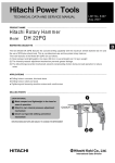
20 mm (3/4”) IMPACT DRILL
DV 20VB2
18 mm (11/16”) IMPACT DRILL
DV 18V
LIST Nos. DV 20VB2: E475
DV 18V: E476
D
TECHNICAL DATA
AND
SERVICE MANUAL
Oct. 2004
SPECIFICATIONS AND PARTS ARE SUBJECT TO CHANGE FOR IMPROVEMENT
REMARK:
Throughout this TECHNICAL DATA AND SERVICE MANUAL, a symbol(s)
is(are) used in the place of company name(s) and model name(s) of our
competitor(s). The symbol(s) utilized here is(are) as follows:
Model DV 20VB2
Competitors
Symbols Utilized
Company Name
Model Name
B
BOSCH
GSB20-2RE
C
MAKITA
HP2051
H
METABO
SBE750
Model DV 18V
Competitors
Symbols Utilized
Company Name
Model Name
B
BOSCH
GSB18-2RE
H
METABO
SBE660
CONTENTS
Page
1. PRODUCT NAME .......................................................................................................................... 1
2. MARKETING OBJECTIVE ............................................................................................................ 1
3. APPLICATIONS ............................................................................................................................. 1
4. SELLING POINTS ......................................................................................................................... 1
4-1. Selling Point Descriptions ............................................................................................................. 2
5. SPECIFICATIONS ......................................................................................................................... 3
5-1. Specifications ................................................................................................................................ 3
6. COMPARISONS WITH SIMILAR PRODUCTS ............................................................................. 5
6-1. Specification Comparisons ........................................................................................................... 5
6-2. Drilling Speed Comparisons ......................................................................................................... 6
7. PRECAUTIONS IN SALES PROMOTION .................................................................................... 7
7-1. Handling Instructions .................................................................................................................... 7
7-2. Cautions on Name Plate ............................................................................................................... 7
7-3. Precautions on Usage .................................................................................................................. 8
8. PRECAUTIONS IN DISASSEMBLY AND REASSEMBLY ......................................................... 11
8-1. Disassembly ................................................................................................................................ 11
8-2. Reassembly ................................................................................................................................ 16
8-3. Wiring Diagrams ......................................................................................................................... 19
8-4. Internal Wire Arrangement and Wiring Work .............................................................................. 20
8-5. Insulation Tests ........................................................................................................................... 23
8-6. No-Load Current Value ............................................................................................................... 23
9. STANDARD REPAIR TIME (UNIT) SCHEDULES ...................................................................... 24
Model DV 20VB2 ............................................................................................................................... 24
Model DV 18V .................................................................................................................................... 25
Assembly Diagram for DV 20VB2
Assembly Diagram for DV 18V
1. PRODUCT NAME
Hitachi 20 mm (3/4") Impact Drill, Model DV 20VB2
Hitachi 18 mm (11/16") Impact Drill, Model DV 18V
2. MARKETING OBJECTIVE
The Models DV 20VB2 and DV 18V are upgraded versions of the current Models DV 20VB, DV 20VC, DV 20T2,
VTP-18 and VTV-18. The performance is greatly improved.
These two models are developed under the concept for compact, lightweight and powerful. The main features of
the Models DV 20VB2 and DV 18V are as follows:
(1) Compact and lightweight
(2) Class-top drilling speed
(3) Powerful motor
(4) Shortest chuck offset
(5) Durable aluminum gear cover and inner cover
(6) Two-finger sized trigger switch with speed control dial
3. APPLICATIONS
(1) Rotation and impacting function
Drilling into concrete, brick, ceramic tile, marble, granite and other stone materials
(2) Rotation only function
Drilling into metal, wood and plastics
4. SELLING POINTS
Compact and lightweight
Overall length: 333 mm (13-1/8")*
Weight:
DV 20VB2: 2.2 kg (4.9 lbs.)
DV 18V : 2.0 kg (4.4 lbs.)
Class-top drilling speed
Powerful motor
Power input:
DV 20VB2: 790 W
(120 V 8.3 A for U. S. A.)
DV 18V: 690 W
*339 mm (13-11/32") with the slip clutch
Soft grip handle for
increased comfort
Shortest chuck offset
23.5 mm (15/16")
Push button type
forward-reverse
changeover switch
Durable aluminum gear
cover and inner cover
Slip clutch mechanism
(Only the Model DV 20VB2
for specific destinations)
Two-finger sized trigger switch
with speed control dial
--- 1 ---
4-1. Selling Point Descriptions
(1) Compact and lightweight design for less user fatigue
To make the Models DV 20VB2 and DV 18V compact is the first priority at designing. Entire length of these
models is 333 mm (13-1/8")*1 and the chuck offset is 23.5 mm (15/16"). The Model DV 20VB2 weighs 2.2 kg
(4.9 lbs.). The Model DV 18V weighs 2.0 kg (4.4 lbs.). Its ease of operation is the class-top level.
*1: 339 mm (13-11/32") with the slip clutch
(2) Class-top drilling speed
Thanks to the powerful motor (rated power consumption: DV 20VB2 790 W (120 V, 8.3 A), DV 18V 690 W),
the Models DV 20VB2 and DV 18V can drill at the class-top speed while it is compact and lightweight. And
powerful motor also provides high performance for heavy-duty applications.
(3) Easy-to-operate 2-finger sized trigger switch with speed control dial
The pulling amount of the trigger can be adjusted on the dial. It is convenient for operation keeping at a
desired speed. The large variable speed control dial and the 2-finger sized trigger switch are easy to operate.
(4) Reliable and convenient push-button type forward/reverse changeover switch
The Models DV 20VB2 and DV 18V are equipped with the push-button type forward/reverse changeover
switch that is more convenient and reliable than the lever-type switch. In addition, this switch is properly
shaped and located not to make the pushbutton an obstacle at drilling.
(5) Durable aluminum die-casting inner cover and gear cover
The Models DV 20VB2 and DV 18V are equipped with the aluminum die-casting inner cover and gear cover
for increased durability.
(6) Slip clutch mechanism (Only the Model DV 20VB2 for specific destinations)
The Model DV 20VB2 for specific destinations is equipped with the slip clutch mechanism to avoid direct and
strong reaction force caused by application of a sudden and heavy load by slipping the transmission portion
between the motor and the drill bit.
--- 2 ---
5. SPECIFICATIONS
5-1. Specifications
Model
DV 20VB2
Capacities Concrete
Low speed: 20 mm (3/4") / High speed: 13 mm (1/2")
Steel
Low speed: 13 mm (1/2") / High speed: 8 mm (5/16")
Wood
Low speed: 40 mm (1-9/16") / High speed: 25 mm (1")
Drill chuck
Mount type: UNF 1/2" --- 20
Capacity: 13 mm (1/2")
Type of motor
Enclosure
AC single phase commutator motor
Housing
Handle
Inner cover
Gear cover
Glassfiber reinforced polycarbonate + elastomer
Aluminum alloy die casting
Type of switch
Variable speed control trigger switch with reversing switch
Power source
AC single phase 50/60 Hz
Rated voltage
(110 V, 120 V, 230 V, 240 V)
Rated current
110 V: 7.6 A 120 V: 8.3 A*1 230 V: 3.6 A 240 V: 3.5 A
Power input
790 W
Cord
2-core cabtire cord 2.5 m (8.3 ft.)
No-load speed
0 --- 1000/3000/min
Full-load impact rate
8000/26000/min
Full-load output
440 W
Weight
2
Net*
2.2 kg (4.9 lbs.)
Gross
4.2 kg (9.3 lbs.)
Packaging
Plastic carrying case
Standard accessories
Side handle • • • • • •••••••••••••••••••••••••••••••••••••••••••••••••••••••••••••••••••••••••••••••••• •• 1
Depth gauge • • • •••••••••••••••••••••••••••••••••••••••••••••••••••••••••••••••••••••••••••••••••• ••• 1
Chuck wrench (spec. only for chuck with chuck wrench ) •••••••••••••••••••••••••• • 1
Plastic carrying case •••••••••••••••••••••••••••••••••••••••••••••••••••••••••••••••••••••••••••• • 1
Optional accessories
Drill bit for concrete
*1 : For U.S.A. and Canada only
*2 : Without cord
--- 3 ---
Model
DV 18V
Capacities Concrete
Low speed: 18 mm (11/16") / High speed: 13 mm (1/2")
Steel
Low speed: 13 mm (1/2") / High speed: 8 mm (5/16")
Wood
Low speed: 40 mm (1-9/16") / High speed: 25 mm (1")
Drill chuck
Mount type: UNF 1/2" --- 20
Capacity: 13 mm (1/2")
Type of motor
AC single phase commutator motor
Enclosure Housing
Handle
Inner cover
Gear cover
Glassfiber reinforced polycarbonate + elastomer
Aluminum alloy die casting
Type of switch
Variable speed control trigger switch with reversing switch
Power source
AC single phase 50/60 Hz
Rated voltage
(110 V, 220 V, 230 V, 240 V)
Rated current
110 V: 6.6 A 220 V: 3.3 A 230 V: 3.2 A 240 V: 3.0 A
Power input
690 W
Cord
2-core cabtire cord 2.5 m (8.3 ft.)
No-load speed
0 --- 1000/3000/min
Full-load impact rate
8000/26000/min
Full-load output
340 W
Weight
1
Net*
2.0 kg (4.4 lbs.)
Gross
4.2 kg (9.3 lbs.) including the case. 3 kg (6.6 lbs.) excluding the case.
Packaging
Corrugated cardboard box or plastic carrying case
Standard accessories
Side handle • • • • • • • • • • • • • ••••••••••••••••••••••••••••••••••••••••••••••••••••••••••••••••••••••••••••••••• 1
Depth gauge • • • • • • • • • • • • ••••••••••••••••••••••••••••••••••••••••••••••••••••••••••••••••••••••••••••••••• 1
Chuck wrench (spec. only for chuck with chuck wrench ) ••••••••••••••••••••••••••••••• • 1
Plastic carrying case (provided only for the models specified to include the case) •• • 1
Optional accessories
Drill bit for concrete
*1 : Without cord
--- 4 ---
6. COMPARISONS WITH SIMILAR PRODUCTS
6-1. Specification Comparisons
700 W class
Maker
HITACHI
Model
Capacities
No-load impact rate
Max. torque
DV 20VB
20 (3/4")
20 (3/4")
H
C
B
(Reference)
20 (3/4")
20 (3/4")
20 (3/4")
Concrete
mm (in.)
Steel
mm (in.)
13 (1/2")
13 (1/2")
13 (1/2")
13 (1/2")
13 (1/2")
Wood
mm (in.)
40 (1-9/16")
40 (1-9/16")
40 (1-9/16")
40 (1-9/16")
40 (1-9/16")
750
750
720
(120 V: 8.2 A)
800
Rated power input
No-load speed
DV 20VB2
W
790
(120 V: 8.3 A)
/min.
0
1,000
0
1,100
0
1,000
0
1,200
0
1,100
High
/min.
0
3,000
0
2,600
0
3,000
0
2,900
0
3,000
Low
/min.
0
13,000
0
17,600
0
19,000
0
24,000
0
17,600
High
/min.
0
39,000
0
41,600
0
57,000
0
58,000
0
48,000
Low
N. m
1
54.1 (29.5) *
44.5
High
N. m
19.6 (10.7) *1
18.1
Low
No-load noise level
79
81
79
81
87
Housing structure
Cylindrical
Cylindrical
Cylindrical
Cylindrical
Cylindrical
Gear cover material
Aluminum
Plastic
Aluminum
Aluminum
Aluminum
Brush shift
Lever
Brush shift
dB
*2
Slip clutch
Soft grip handle
Speed control dial
Type of reversing switch
Overall length
Push button
mm (in.)
339 (13-11/32") *
Lever
2
340 (13-3/8")
368 (14-31/64") 360 (14-3/16") 356 (14-1/64")
/333 (13-1/8")
Chuck offset
mm (in.)
23.5 (15/16")
29.0 (1-5/32")
27.5 (1-3/32")
24.5 (31/32")
30.0 (1-3/16")
Weight
kg (lbs.)
2.2 (4.9 lbs.)
2.3 (5.1 lbs.)
2.3 (5.1 lbs.)
2.3 (5.1 lbs.)
2.6 (5.7 lbs.)
* 1 : With the slip clutch
* 2 : Depends on the destinations.
600 W class
Maker
HITACHI
Model
DV 18V
Concrete
Capacities
mm (in.)
18 (11/16")
H
B
(Reference)
18 (11/16")
16 (5/8")
18 (11/16")
13 (1/2")
13 (1/2")
13 (1/2")
30 (1-3/16")
40 (1-9/16")
VTP-18
VTV-18
18 (11/16")
13 (1/2")
Steel
mm (in.)
13 (1/2")
Wood
mm (in.)
40 (1-9/16")
Low
/min.
0
1,000
0
1,050
High
/min.
0
3,000
0
1,800
Low
/min.
0
13,000
0
21,000
High
/min.
0
39,000
0
36,000
0
Low
N. m
53.0
27.8
27.8
35.7
30.2
High
N. m
19.2
17.2
17.2
11.8
10.3
dB
79
82
82
79
85
Housing structure
Cylindrical
Cylindrical
Cylindrical
Cylincrical
Clamshell
Gear cover material
Aluminum
Aluminum
Aluminum
Aluminum
Rated power input
No-load speed
No-load impact rate
Max. torque
690
W
No-load noise level
640
640
750
660
1,050
0
1,000
0
1,800
0
3,000
0
3,000
0
21,000
0
19,000
0
16,000
36,000
0
57,000
0
0
0
1,000
48,000
Slip clutch
Soft grip handle
Speed control dial
Type of reversing switch
Push button
Overall length
mm (in.)
333 (13-1/8")
340 (13-3/8")
Chuck offset
mm (in.)
23.5 (15/16")
25.0 (1")
Weight
kg (lbs.)
2.0 (4.4 lbs.)
2.3 (5.1 lbs.)
--- 5 ---
Brush shift
Brush shift
340 (13-3/8")
359 (14-9/64")
346 (13-5/8")
25.0 (1")
27.5 (1-3/32")
30 (1-3/16")
2.3 (5.1 lbs.)
2.1 (4.6 lbs.)
2.2 (5.1 lbs.)
6-2. Drilling Speed Comparisons
Drilling speed depends on the operating conditions. The test results are based on actual factory tests, and should
be used as a reference only.
700 W class
500
450
Drilling speed [mm/min]
400
Test condition:
Mortar panel compression strength: 24 N/mm2
Pressing force: 300 N
360
348
300
258
210
200
100
0
DV 20VB2
HITACHI
B
DV 20VB
HITACHI
H
C
Maker
600 W class
500
450
Test condition:
Mortar panel compression strength: 24 N/mm2
Pressing force: 300 N
Drilling speed [mm/min]
400
348
329
276
300
200
100
0
DV 18V
HITACHI
VTP-18
HITACHI
B
Maker
--- 6 ---
H
7. PRECAUTIONS IN SALES PROMOTION
In the interest of promoting the safest and most efficient use of the Models DV 20VB2 and DV 18V Impact Drills
by all of our customers, it is very important that at the time of sales the salesperson carefully ensures that the
buyer seriously recognizes the importance of the contents of the Handling Instructions, and fully understands the
meaning of the precautions listed on the Caution Plate attached to each tool.
7-1. Handling Instructions
Although every effort is made in each step of design, manufacture and inspection to provide protection against
safety hazards, the dangers inherent in the use of any electric power tool cannot be completely eliminated.
Accordingly, general precautions and suggestions for the use of electric power tools, and specific precautions
and suggestions for the use of the Impact Drill are listed in the Handling Instructions to enhance the safe, efficient
use of the tool by the customer. Salespersons must be thoroughly familiar with the contents of the Handling
Instructions to be able to offer appropriate guidance to the customer during sales promotion.
7-2. Cautions on Name Plate
The following basic safety precautions are listed on the Name Plate attached to the main body of each tool.
For Australia, New Zealand and China
CAUTION
Read thoroughly HANDLING INSTRUCTIONS before use.
For the U.S.A. and Canada
WARNING
To reduce the risk of injury, user must read and
understand the instruction manual.
AVERTISSEMENT
Afin de reduire le risque de blessures, l'utilisateur doit lire
et bien comprendre le mode d'emloi.
These precautions are not listed on the Name Plates of the products destined for the countries other than
Oceania, China, the U.S.A. and Canada.
--- 7 ---
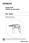
7-3. Precautions on Usage
Change lever
(1) IMPACT to ROTATION changeover
Shift the change lever between the right and left
positions to switch easily between IMPACT
(rotation and impact) and ROTATION (rotation
only), respectively.
To bore holes in hard materials such as concrete,
stone and tiles, shift the change lever to the righthand position (as indicated by the
mark).
The drill bit operates by the combined actions of
Fig. 1
impact and rotation.
To bore holes in metal, wood and plastic, shift the change lever to the left-hand position (as indicated by the
mark). The drill bit operates by rotational action only, as in the case of a conventional elecric drill.
CAUTION:
Do not use the hammer drill in the IMPACT function if the material can be bored by rotation only.
Such action will not only reduce drill efficiency, but may also damage the drill tip.
Operating the hammer drill with the change lever in mid-position may result in damage.
When switching, make sure that you shift the change lever to the correct position.
NOTE:
The change lever may not shift smoothly when changing from hammer drill mode to drill mode.
In this case, switch ON and operate the machine for few seconds. The spindle shaft will then be
pushed forward, and the change lever can be moved smoothly.
(2) High-speed/low-speed changeover
Prior to changing speed, ensure that the switch is
in the OFF position, and the drill has come to a
complete stop.
To change speed, rotate the gear shift dial as
indicated by the arrow in Fig. 2. The numeral "1"
Gear shift dial
engraved on the drill body denotes low speed, the
numeral "2" denotes high speed.
If it is hard to turn the gear shift dial, turn the
chuck slightly in either direction and then turn the
gear shift dial again.
Fig. 2
--- 8 ---
(3) Check the rotational direction
The bit rotates clockwise (viewed from the rear side) by pushing the R-side of the push button.
The L-side of the push button is pushed to turn the bit counterclockwise.
(The L and R marks are provided on the body.)
CAUTION: Always use the hammer drill with clockwise rotation, when using it as an hammer drill.
L mark
Push button
Switch trigger
R mark
Fig. 3
(4) Switch operation
When the trigger switch is depressed, the tool rotates.
When the trigger is released, the tool stops.
Stopper
The rotational speed of the drill can be controlled by
varying the amount that the trigger switch is pulled.
Speed
control dial
Speed is low when the trigger switch is pulled slightly
Low speed
High
speed
and increases as the trigger switch is pulled more.
The desired rotation speed can be preselected with the
speed control dial. Turn the speed control dial clockwise
for higher speed and counterclockwise for lower speed.
Switch
trigger
Fig. 4
Pulling the trigger and pushing the stopper, it keeps the switched-on condition which is convenient for
continuous running. When switching off, the stopper can be disconnected by pulling the trigger again.
NOTE: If the L-side of push button is pressed for reverse bit rotation, the stopper cannot be used.
--- 9 ---
(5) Drilling
When drilling, start the drill slowly, and gradually increasing speed as you drill.
Always apply pressure in a straight line with the bit. Use enough pressure to keep drilling, but do not push
hard enough to stall the motor or deflect the bit.
To minimize stalling or breaking through the material, reduce pressure on drill and ease the bit through the
last part of the hole.
If the drill stalls, release the trigger immediately, remove the bit from the work and start again. Do not click the
trigger on and off in an attempt to start a stalled drill. This can damage the drill.
WARNING: The larger the drill bit diameter, the larger the reactive force on your arm. Be careful not to
lose control of the drill because of this reactive force. To maintain firm control, establish
a good foothold, use side handle, hold the drill tightly with both hands, and ensure that
the drill is vertical to the material being drilled.
(6) Slip clutch mechanism (Only the Model DV 20VB2 for specific destinations)
The Model DV 20VB2 (only for specific destinations) is equipped with the slip clutch mechanism to avoid direct
and strong reaction force caused by application of a sudden and heavy load by slipping the transmission
portion between the motor and the drill bit.
CAUTION:
Turn off the switch immediately if the rotation of the drill bit is stopped by the slip clutch. Be careful
not to actuate the slip clutch frequently.
The spindle shaft torque and the reaction force applied to the side handle when the slip clutch
actuates are shown in the table below. In the case of the low gear, the reaction force applied to the
side handle may be 345.1 N {35.2 kgf} at the maximum. Instruct the customers to use the side handle
without fail and securely hold the Model DV 20VB2 with both hands standing on a good foothold, not
to be affected by the reaction force.
Spindle shaft torque
High gear
Low gear
Reaction force applied to
the side handle
N
kgf
42.6
4.3
N.m
kgf.m
Minimum
5.4
0.6
Maximum
15.9
1.6
124.9
12.7
Minimum
15.0
1.5
117.6
12.0
Maximum
44.0
4.5
345.1
35.2
--- 10 ---
8. PRECAUTIONS IN DISASSEMBLY AND REASSEMBLY
The numbers in the descriptions below correspond to the item numbers in the Parts List and exploded assembly
diagram.
The [Bold] numbers are for the Model DV 20VB2, the <Bold> numbers for the Model DV 18V.
8-1. Disassembly
8-1-1. Motor section disassembly
(1) Removal of the handle cover
Loosen the Tapping Screws (W/Flange) D4 x 20 (Black) [40] <39>, and remove the Handle Cover [41] <40>.
(2) Removal of the carbon brushes
With a small flat-blade screwdriver, slightly lift the Brush Holders [47] <46>. Then, while pushing the Carbon
Brushes (1 Pair) [46] <45> to the bottom of the brush holders, gently pull out and disconnect the internal wire
terminals. (See Figs. 5 and 6.)
Terminal
Carbon brush
stop piece
Carbon brush
stop piece
Pull out
Carbon brush
Terminal
Brush holder
Projection
Push
Fig. 5
Fig. 6
(3) Removal of the gear cover from the housing
Loosen the Tapping Screws (W/Flange) D5 x 45 (D5 x 50: with clutch) [12] <12> and separate Gear Cover (A)
Ass'y [25] <25> from the Housing [38] <37>. Then, remove the Inner Cover [18] <18> together with the
Armature [33] <32> from the Housing [38] <37>.
--- 11 ---
(4) Removal of the armature from the inner cover
As illustrated in Fig. 9, support the Inner Cover [18] <18> with a tubular jig, and push down on the top of the
pinion of the Armature [33] <32>.
Push.
Pinion
Inner Cover [18] <18>
Armature [33] <32>
Fig. 7
(5) Removal of the stator from the housing
First, disconnect the internal wires from the Switch (1P Pillar Type) [43] <42>. To disconnect the internal wires
from the switch, insert a small flat-blade screwdriver into the windows near the terminals and pull out the
internal wires. Remove the Hex. Hd. Tapping Screws D4 x 50 [35], D4 x 45 <34> and tap the end surface of
the Housing [38] <37> slightly with a wooden hammer. Then the stator can be removed from the housing.
8-1-2. Inner cover ass'y disassembly
Removal of the change lever
Remove the Change Cover [16] <16> and the Change Lever [15] <15>.
--- 12 ---
8-1-3. Removal of the drill chuck
The Drill Chuck [3] <3> is secured to the Spindle [4] <4> with 1/2"-20 UNF (right hand) and Flat Hd. Screw (A)
(Left Hand) M6 x 25 [1] <1>. At first, open the chuck jaw as far as possible and loosen Flat Hd. Screw (A) (Left
Hand) M6 x 25 [1] <1> by turning it clockwise.
a. Hold the drill so that only the Drill Chuck [3] <3> rests firmly and squarely on the edge of a solid bench.
Install the hex. bar wrench into the drill chuck. Turn the drill chuck until the wrench is at about a 30û angle to
the bench top and strike the wrench sharply with a hammer so the drill chuck turns in the counterclockwise
direction. (Fig. 8)
Flat Hd. Screw (A)
(Left Hand) M6 x 25 [1] <1>
Hex. bar wrench
Loosen
Fig. 8
If the drill chuck cannot be removed by striking the wrench, do not strike the wrench forcibly and try another
way as follows.
b. Hold the Spindle [4] <4> with the open-end wrench secured to the vise as shown in Fig. 9.
Mount the pipe to the hex. bar wrench. Turn the hex. bar wrench counterclockwise to loosen the drill chuck.
(Fig. 9)
Turn it counterclockwise.
Pipe
Hex. bar wrench
Vise
Open-end wrench
Fig. 9
--- 13 ---
c. (For keyed chuck only)
Secure the drill chuck with a disassembly tool: Ring (J-78) to the drill chuck, which in proper sequence should
be secured with a vise. Then fit a disassembly tool: Wrench Ass'y (J-140) to the spindle, and turn it
counterclockwise to loosen the drill chuck. (Fig. 10)
Turn it counterclockwise.
Ring ass'y and ring (J-78)
Wrench ass'y (J-140)
Vise
Drill chuck
Fig. 10
8-1-4. Gear cover section disassembly
(1) Removal of the spindle
Remove the Retaining Ring For D35 Hole [5] <5> and the Dust Seal [6] <6>.
Support the tip of the Gear Cover (A) Ass'y [25] <25> with a cylindrical jig of inside diameter 35 mm or more,
and push the rear portion of the Spindle [4] <4> lightly. Then the spindle can be removed together with the
Ball Bearing 6202DDCMPS2L [7] <7> and Spring (A) [9] <9>. (Fig. 11)
Push.
Spindle [4] <4>
Dia. 35 min.
Fig. 11
--- 14 ---
(2) Removal of the shift lever
Position the Shift Lever Ass'y [19] <19> as shown in Fig. 12. Push both ends of the Retaining Ring (E-type)
for D15 Shaft [26] <26> with a pair of long-nose pliers until a clearance about 1 to 2 mm is made. Keeping the
clearance, turn the Shift Lever Ass'y [19] <19> by 180 degrees together with the Retaining Ring (E-type) for
D15 Shaft [26] <26>. Insert a flat-blade screwdriver into the clearance and pry the Retaining Ring (E-type) for
D15 Shaft [26] <26> off upward.
CAUTION:
If the Retaining Ring (E-type) for D15 Shaft [26] <26> is pushed excessively, the Shift Lever Ass'y [19]
<19> cannot be turned due to a wide clearance.
1
2
Push.
Gear Cover (A) Ass'y [25] <25>
Shift Lever Ass'y [19] <19>
3
Face the shift pin upward.
Turn.
Retaining Ring (E-type)
for D15 Shaft [26] <26>
Clearance
Fig. 12
--- 15 ---
8-2. Reassembly
Reassembly can be accomplished by following the disassembly procedures in reverse. However, special
attention should be given to the following items.
8-2-1. Internal wire arrangement
(1) Arrange the internal wires according to "8-4. Internal Wire Arrangement and Wiring Work".
(2) Be careful not to catch the internal wires when mounting the handle cover.
8-2-2. Lubrication
(1) Apply ATTLUB MS No. 2 Grease to the following parts.
Teeth of the Second Pinion and Gear Set [14] <14>, the Gear Set [29] <29>.
On the Spindle [4] <4>.
Ground portion for fitting the Ball Bearing 6202DDCMPS2L [7] <7>, splined portion and hole of rear side.
On the Shift Lever Ass'y [19] <19>.
Outer circumference portion of the Shift Pin [21] <21>, the O-ring (S-22) [22] <22>.
On the Change Shaft [17] <17>.
Outer circumference portion.
Lip portion of the Dust Seal [6] <6>.
On the Inner Cover [18] <18>.
Metal portion.
Inside of Gear Cover (A) Ass'y [25] <25>: 5 g
(2) Apply MORABUAROI 777-1 to the following parts.
On Gear Cover (A) Ass'y [25] <25>.
Teeth of Ratchet (B) [11] <11>.
Teeth of Ratchet (A) [8] <8>.
8-2-3. Tightening torque
(1) Flat Hd. Scerw (A) (Left Hand) M6 x 25 [1] <1>
•••••••••••••••••••••••••••••••••••••
(2) Tapping Screw (W/Flange) D4 x 20 (Black) [40] <39>
(3) Tapping Screw (W/Flange) D5 x 45 [12] <12>
(4) Drill Chuck [3] <3>
4.0 to 5.0 N•m (39.0 to 47.8 in-lbs.)
••••••••••••••••••••••••••••
1.5 to 2.5 N•m (13.3 to 22.1 in-lbs.)
•••••••••••••••••••••••••••••••••••••••
2.4 to 3.4 N•m (21.3 to 30.1 in-lbs.)
•••••••••••••••••••••••••••••••••••••••••• • • • • • • • • • • • • • • • • • • • • • • • • • • • • • • • • • • • • •
--- 16 ---
29.4 to 39.2 N•m (260 to 347 in-lbs.)
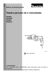
8-2-4. Reassembly of the gear cover section
Figure 13 shows the assembly drawing. Reassemble the gear cover section according to the following figure.
Steel Ball D6.35 [10] <10>
Pin D5 [28] <28>
Second Pinion and Gear Set [14] <14>
Shift Arm [27] <27>
Shift Lever Ass'y [19] <19>
Steel Ball D3.5 [24] <24>
Washer (B) [13] <13>
Spring (H) [23] <23>
Gear Set [29] <29>
Ratchet (B) [11] <11>
Dust Seal [6] <6>
Spring (A) [9] <9>
Ratchet (A) [8] <8>
Retaining Ring for D35 Hole [5] <5>
Ball Bearing
6202DDCMPS2L [7] <7>
Spindle [4] <4>
Fig. 13
CAUTION:
Be sure to replace Ratchet (A) [8] <8> with a new one. Never reuse Ratchet (A) [8] <8> previously removed
from the Spindle [4] <4>. If reused, the tightening torque between Ratchet (A) [8] <8> and the Spindle [4] <4>
will be far too low and the Spindle [4] <4> may run idle in the IMPACT mode.
Mounting directions of the Shift Arm [27] <27> and the Gear Set [29] <29> are specified. Mount these parts in
the specified direction as shown in the above figure.
--- 17 ---
(With slip clutch)
Steel Ball D6.35 [10]
Second Pinion
and Gear Set [14]
Pin D5 [28]
Shift Arm [27]
Shift Lever Ass'y [19]
Steel Ball D3.5 [24]
Washer (B) [13]
Spring (H) [23]
Gear Set [29]
Dust Seal [6]
Ratchet (B) [11]
Spring (A) [9]
Retaining Ring for D35 Hole [5]
Ratchet (A) [8]
Spindle [4]
Ball Bearing
6202DDCMPS2L [7]
Fig. 14
CAUTION:
Be sure to replace Ratchet (A) [8] with a new one. Never reuse Ratchet (A) [8] previously removed from the
Spindle [4]. If reused, the tightening torque between Ratchet (A) [8] and the Spindle [4] will be far too low and
the Spindle [4] may run idle in the IMPACT mode.
Mounting directions of the Shift Arm [27], Gear Set [29] and Spring (A) [9] are specified. Mount these parts in
the specified direction as shown in the above figure.
--- 18 ---
8-3. Wiring Diagrams
(1) For products with noise suppressor
Choke coil
White
Brown
Stator
Black or brown
Gray
Cord ass'y
Noise
suppressor
Stator
Blue
Black
Red
White or blue
Choke coil
Reversing switch
Speed control switch
Fig. 15
(2) For products without noise suppressor
White
Brown
Stator
Black or brown
Gray
Cord ass'y
Stator
Blue
Black
Red
Reversing switch
White or blue
Speed control switch
Fig. 16
--- 19 ---
8-4. Internal Wire Arrangement and Wiring Work
A. Internal wire arrangement
(1) For products with noise suppressor
Natural (Noise suppressor)
CB terminal
Carbon brush
Black (Stator)
Brown (Choke coil)
White (Stator)
Blue (Choke coil)
Armature
Switch
Red (Stator)
Gray (Stator)
15 +50
Noise suppressor
Cord
Fig. 17
--- 20 ---
(2) For products without noise suppressor
Brown
Black (Stator)
White (Stator)
Blue (CB)
Armature
Switch
Red (Stator)
Gray (Stator)
15 +50
Cord
Fig. 18
--- 21 ---
B. Switch connection
(1) Wiring of reversing switch
Blue
(Choke coil/Lead wire)
White
(Stator)
(1)
(3)
(2)
(4)
Black
(Stator)
Brown
(Choke/Lead wire)
Fig. 19
(2) Wiring of speed control switch
Black or brown
(Cord)
(1 )
Red (M2)
(Stator)
(M1)
Gray
(Stator)
Noise suppressor
Fig. 20
--- 22 ---
White or blue
(Cord)
(2 )
8-5. Insulation Tests
On completion of reassembly after repair, measure the insulation resistance and conduct the dielectric strength
test.
Insulation resistance: 7 M Ω or more with DC 500 V megohm tester
Dielectric strength: AC 4,000 V/1 minute, with no abnormalities 220 V --- 240 V (and 110 V for U.K. products)
AC 2,500 V/1 minute, with no abnormalities 110 V --- 127 V (except U.K. products)
8-6. No-Load Current Value
After no-load operation for 30 minutes, the no-load current value should be as follows.
Model DV 20VB2
Voltage (V)
110
120
230
240
Current (A) Max.
3.5
3.2
1.6
1.5
Voltage (V)
110
220
230
240
Current (A) Max.
3.5
1.7
1.6
1.5
Model DV 18V
--- 23 ---
9. STANDARD REPAIR TIME (UNIT) SCHEDULES
MODEL
Variable
Fixed
10
20
30
40
Work Flow
DV 20VB2
Handle Cover
Cord Armor
Switch
Cord
Housing
Stator
General Assembly
Armature
Inner Cover
Ball Bearing
Second Pinion
(608DD)
and Gear Set
Ball Bearing
Change Lever
(608VV)
Change Cover
Change Shaft
Drill Chuck
Spindle
Gear Cover
(A) Ass'y
Ball Bearing
(6202DD) Ratchet (B)
Shift Lever
Ratchet (A)
Ass'y
Spring (A)
Spring (H)
Shift Arm
Gear Set
--- 24 ---
50
60 min.
MODEL
Variable
Fixed
10
20
30
40
Work Flow
DV 18V
Handle Cover
Cord Armor
Switch
Cord
Housing
Stator
General Assembly
Armature
Ball Bearing
(608DD)
Ball Bearing
(608VV)
Inner Cover
Second Pinion
and Gear Set
Change Lever
Change Cover
Change Shaft
Gear Cover
Spindle (B)
(A) Ass'y
Ball Bearing
(6202DD) Ratchet (B)
Shift Lever
Ratchet (A)
Ass'y
Spring (A)
Spring (H)
Shift Arm
Gear Set
Drill Chuck
--- 25 ---
50
60 min.
Hitachi Power Tools
LIST NO. E475
ELECTRIC TOOL PARTS LIST
IMPACT DRILL
Model DV 20VB2
2004
•
4 • 20
(E1)
1
2
3
3
3
5
6
4
7
8
9
10
11
12
13
19
31
21
32
22
14
13
20
33
15
23
25
24
34
16
26
27
35
17
28
18
36
29
37
30
38
48
39
47
46
45
44
501
43
42
41
502
55
54
53
503
52
40
51
50
49
56
PARTS
ITEM
NO.
*
1
DV 20VB2
NO.
USED
CODE NO.
DESCRIPTION
995-344
FLAT HD. SCREW (A) (LEFT HAND) M6X25
1 EXCEPT FOR DRILL CHUCK 13VLN
REMARKS
2
987-576
CHUCK WRENCH FOR 13VLB-D, 13VLR-D
1
*
3
321-814
DRILL CHUCK 13VLRB-D
1 INCLUD. 1, 2
*
3
319-546
DRILL CHUCK 13VLRE-N (W/O CHUCK WRENCH)
1
*
3
316-280
DRILL CHUCK 13VLN (W/O CHUCK WRENCH)
1
*
4
322-857
SPINDLE (B)
1
*
4
322-866
SPINDLE (A)
1 FOR SLIP CLUTCH
5
939-556
RETAINING RING FOR D35 HOLE (10 PCS.)
1
6
322-851
DUST SEAL
1
7
620-2DD
BALL BEARING 6202DDCMPS2L
1
8
322-850
RATCHET (A)
1
9
984-101
SPRING (A)
1
10
959-150
STEEL BALL D6.35 (10 PCS.)
1
11
322-845
RATCHET (B)
1
*
12
316-321
TAPPING SCREW (W/FLANGE) D5X45
4
*
12
322-869
TAPPING SCREW (W/FLANGE) D5X50 (BLACK)
4 FOR SLIP CLUTCH
13
322-852
WASHER (B)
2
*
14
322-858
SECOND PINION AND GEAR SET
1
*
14
322-867
SECOND PINION AND GEAR SET
1 FOR SLIP CLUTCH
15
322-841
CHANGE LEVER
1
16
322-842
CHANGE COVER
1
17
322-840
CHANGE SHAFT
1
*
18
322-859
INNER COVER (B)
1
*
18
322-868
INNER COVER (A)
1 FOR SLIP CLUTCH
19
322-847
SHIFT LEVER ASS’Y
1 INCLUD. 20-22
SHIFT LEVER
1
21
322-848
SHIFT PIN
1
22
306-353
O-RING (S-22)
1
23
981-328
SPRING (H)
1
24
319-535
STEEL BALL D3.5 (10 PCS.)
1
25
322-844
GEAR COVER (A) ASS’Y
1 INCLUD. 11
26
323-048
RETAINING RING (E-TYPE) FOR D15 SHAFT
1
20
27
322-849
SHIFT ARM
1
*
28
322-860
PIN D5
1
*
28
984-104
PIN D5
1 FOR SLIP CLUTCH
29
322-846
GEAR SET
1
*
30
31
LABEL (FOR SLIP CLUTCH)
1 FOR SLIP CLUTCH
608-DDM BALL BEARING 608DDC2PS2L
1
32
939-553
*
33
360-652C ARMATURE 110V
1
*
33
360-652U ARMATURE ASS’Y 120V
1 INCLUD. 31, 37
*
33
360-652E ARMATURE 230V
1
*
33
360-652F ARMATURE 240V
1
34
322-843
FAN GUIDE
1
HEX. HD. TAPPING SCREW D4X50
2
RETAINING RING FOR D22 HOLE (10 PCS.)
1
35
961-672
*
36
340-587C STATOR 110V
1
*
36
340-587D STATOR 120V
1
*
36
340-587E STATOR 230V
1
*
36
340-587F STATOR 240V
1
37
608-VVM
BALL BEARING 608VVC2PS2L
1
38
322-861
HOUSING
1
--- 2 ---
* ALTERNATIVE PARTS
4 -- 04
PARTS
ITEM
NO.
39
DV 20VB2
NO.
USED
CODE NO.
DESCRIPTION
NAME PLATE
1
40
301-653
TAPPING SCREW (W/FLANGE) D4X20 (BLACK)
3
41
322-862
HANDLE COVER
1
REMARKS
42
322-853
PUSHING BUTTON
1
43
322-854
SWITCH (1P PILLAR TYPE)
1
*
44
321-630
INTERNAL WIRE (BROWN) 100L
1 FOR SIN, USA, CAN
*
45
322-517
CHOKE COIL (BROWN) 220V-240V
1 EXCEPT FOR SIN, USA, CAN
*
45
322-518
CHOKE COIL (BROWN) 110V
1 FOR GBR (110V)
46
999-041
CARBON BRUSH (1 PAIR)
2
47
955-203
BRUSH HOLDER
2
HITACHI LABEL
1
48
*
49
994-273
NOISE SUPPRESSOR
1 EXCEPT FOR SIN, USA, CAN
*
50
992-635
EARTH TERMINAL
1 EXCEPT FOR SIN, USA, CAN
*
51
321-631
INTERNAL WIRE (BLUE) 55L
1 FOR SIN, USA, CAN
*
52
321-634
CHOKE COIL (BLUE) 110V-240V
1 EXCEPT FOR SIN, USA, CAN
*
52
322-519
CHOKE COIL (BLUE) 110V
1 FOR GBR (110V)
53
984-750
TAPPING SCREW (W/FLANGE) D4X16
2
54
937-631
CORD CLIP
1
CORD ARMOR D8.8
1
55
953-327
*
56
500-409Z CORD
1 (CORD ARMOR D8.8)
*
56
500-423Z CORD
1 (CORD ARMOR D8.8) FOR SIN
*
56
500-439Z CORD
1 (CORD ARMOR D8.8) FOR NZL, AUS
*
56
500-247Z CORD
1 (CORD ARMOR D8.8) FOR NOR, FIN
*
56
500-240Z CORD
1 (CORD ARMOR D8.8) FOR USA, CAN
*
56
500-461Z CORD
1 (CORD ARMOR D8.8) FOR GBR (110V)
*
56
500-435Z CORD
1 (CORD ARMOR D8.8) FOR GBR (230V)
*
56
500-447Z CORD
1 (CORD ARMOR D8.8) FOR SUI
4 -- 04
* ALTERNATIVE PARTS
--- 3 ---
DV 20VB2
STANDARD ACCESSORIES
ITEM
NO.
501
CODE NO.
DESCRIPTION
NO.
USED
322-706
CASE
1
502
323-050
SIDE HANDLE
1
503
303-709
DEPTH GAUGE
1
REMARKS
OPTIONAL ACCESSORIES
ITEM
NO.
601
CODE NO.
DESCRIPTION
NO.
USED
931-851
DRILL BIT (B) D6.5X100
1
602
931-852
DRILL BIT (B) D8.0X100
1
603
931-853
DRILL BIT (B) D9.5X120
1
604
931-854
DRILL BIT (B) D10.0X120
1
605
971-704
DRILL BIT (B) D12.0X160
1
606
931-855
DRILL BIT (B) D13.0X160
1
607
931-776
DRILL BIT (B) D14.3X160
1
608
971-670
DRILL BIT (B) D16.0X160
1
609
931-856
DRILL BIT (B) D19.0X160
1
--- 4 ---
* ALTERNATIVE PARTS
REMARKS
Printed in Japan 4 -- 04
(040420N)
Hitachi Power Tools
LIST NO. E476
ELECTRIC TOOL PARTS LIST
IMPACT DRILL
Model DV 18V
2004
4 • 20
•
(E1)
2
1
3
3
6
4
7
8
5
9
10
11
12
13
19
21
30
22
14
13
20
31
32
15
23
25
24
16
26
33
27
34
17
28
18
29
35
36
37
38
47
46
45
44
43
501
42
41
40
502
54
503
53
52
51
50
39
49
48
55
PARTS
ITEM
NO.
1
*
2
*
3
*
DV 18V
DESCRIPTION
NO.
USED
995-344
FLAT HD. SCREW (A) (LEFT HAND) M6X25
1
987-576
CHUCK WRENCH FOR 13VLB-D,13VLR-D
1
DRILL CHUCK
1 INCLUD. 1, 2 SUPPLIED WITH ITEM NO. 601
CODE NO.
3
322-357
DRILL CHUCK 13VLRH-N (W/O CHUCK WRENCH)
1
4
322-857
SPINDLE (B)
1
5
939-556
RETAINING RING FOR D35 HOLE (10 PCS.)
1
6
322-851
DUST SEAL
1
7
620-2DD
BALL BEARING 6202DDCMPS2L
1
8
322-850
RATCHET (A)
1
REMARKS
9
984-101
SPRING (A)
1
10
959-150
STEEL BALL D6.35 (10 PCS.)
1
11
322-845
RATCHET (B)
1
12
316-321
TAPPING SCREW (W/FLANGE) D5X45
4
13
322-852
WASHER (B)
2
14
322-858
SECOND PINION AND GEAR SET
1
15
322-841
CHANGE LEVER
1
16
322-842
CHANGE COVER
1
17
322-840
CHANGE SHAFT
1
18
322-859
INNER COVER (B)
1
19
322-847
SHIFT LEVER ASS’Y
1 INCLUD. 20-22
SHIFT LEVER
1
21
322-848
SHIFT PIN
1
22
306-353
O-RING (S-22)
1
20
23
981-328
SPRING (H)
1
24
319-535
STEEL BALL D3.5 (10 PCS.)
1
25
322-844
GEAR COVER (A) ASS’Y
1 INCLUD. 11
26
323-048
RETAINING RING (E-TYPE) FOR D15 SHAFT
1
27
322-849
SHIFT ARM
1
28
322-860
PIN D5
1
29
322-846
GEAR SET
1
30
608-DDM BALL BEARING 608DDC2PS2L
1
31
939-553
1
*
32
360-655C ARMATURE 110V
1
*
32
360-655E ARMATURE 220V-230V
1
*
32
360-655F ARMATURE 240V
1
33
322-843
FAN GUIDE
1
HEX. HD. TAPPING SCREW D4X45
2
RETAINING RING FOR D22 HOLE (10 PCS.)
34
981-824
*
35
340-589C STATOR 110V
1
*
35
340-589E STATOR 220V-230V
1
*
35
340-589F STATOR 240V
1
36
608-VVM
BALL BEARING 608VVC2PS2L
1
37
322-861
HOUSING
1
NAME PLATE
1
38
39
301-653
TAPPING SCREW (W/FLANGE) D4X20 (BLACK)
3
40
322-862
HANDLE COVER
1
41
322-853
PUSHING BUTTON
1
42
322-854
SWITCH (1P PILLAR TYPE)
1
*
43
321-630
INTERNAL WIRE (BROWN) 100L
1 FOR SYR, THA, INA, KUW, IND, SIN, HKG
*
44
322-517
CHOKE COIL (BROWN) 220V-240V
1 FOR ITA, ESP, GBR (230V), NZL, AUS,
*
44
322-518
CHOKE COIL (BROWN) 110V
1 FOR GBR (110V)
AUT, SAF, CHN
--- 2 ---
* ALTERNATIVE PARTS
4 -- 04
PARTS
ITEM
NO.
45
46
DV 18V
CODE NO.
NO.
USED
DESCRIPTION
999-041
CARBON BRUSH (1 PAIR)
2
955-203
BRUSH HOLDER
2
47
REMARKS
HITACHI LABEL
1
*
48
994-273
NOISE SUPPRESSOR
1
FOR GBR (230V), NZL, AUS
*
49
992-635
EARTH TERMINAL
1
FOR GBR (230V), NZL, AUS
*
50
321-631
INTERNAL WIRE (BLUE) 55L
1
FOR SYR, THA, INA, KUW, IND, SIN, HKG
*
51
321-634
CHOKE COIL (BLUE) 110V-240V
1
FOR ITA, ESP, GBR (230V), NZL, AUS,
*
51
322-519
CHOKE COIL (BLUE) 110V
1
FOR GBR (110V)
52
984-750
TAPPING SCREW (W/FLANGE) D4X16
2
53
937-631
CORD CLIP
1
CORD ARMOR D8.8
AUT, SAF, CHN
54
953-327
*
55
500-231Z CORD
1
(CORD ARMOR D8.8)
*
55
500-447Z CORD
1
(CORD ARMOR D8.8) FOR SYR
*
55
500-468Z CORD
1
(CORD ARMOR D8.8) FOR THA
*
55
500-409Z CORD
1
(CORD ARMOR D8.8) FOR INA
*
55
500-423Z CORD
1
(CORD ARMOR D8.8) FOR KUW, SIN
*
55
500-435Z CORD
1
(CORD ARMOR D8.8) FOR GBR (230V), HKG
*
55
500-461Z CORD
1
(CORD ARMOR D8.8) FOR GBR (110V)
*
55
500-439Z CORD
1
(CORD ARMOR D8.8) FOR NZL, AUS
*
55
500-468Z CORD
1
(CORD ARMOR D8.8) FOR CHN
*
55
500-409Z CORD
1
(CORD ARMOR D8.8) FOR IND
4 -- 04
1
* ALTERNATIVE PARTS
--- 3 ---
DV 18V
STANDARD ACCESSORIES
ITEM
NO.
501
CODE NO.
DESCRIPTION
NO.
USED
322-706
CASE
1
502
323-050
SIDE HANDLE
1
503
303-709
DEPTH GAUGE
1
REMARKS
OPTIONAL ACCESSORIES
ITEM
NO.
601
CODE NO.
DESCRIPTION
NO.
USED
321-814
DRILL CHUCK 13VLRB-D
1 INCLUD. 602
602
930-515
CHUCK WRENCH 10G
1
603
931-851
DRILL BIT (B) D6.5X100
1
604
931-852
DRILL BIT (B) D8.0X100
1
605
931-853
DRILL BIT (B) D9.5X120
1
606
931-854
DRILL BIT (B) D10.0X120
1
607
971-704
DRILL BIT (B) D12.0X160
1
608
931-855
DRILL BIT (B) D13.0X160
1
609
931-776
DRILL BIT (B) D14.3X160
1
610
971-670
DRILL BIT (B) D16.0X160
1
611
931-856
DRILL BIT (B) D19.0X160
1
--- 4 ---
* ALTERNATIVE PARTS
REMARKS
Printed in Japan
(040420N)
4 -- 04