1
Issue Date:
2011-12-06
Page 1 of 45
Report Reference #
E142692-A138-CB-2
Test Report issued under
the responsibility of:
UL International Demko A/S
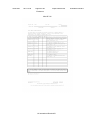
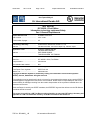
TEST REPORT
IEC 60950-1,First Edition
Information technology equipment-Safety
Part 1:General Requirements
Report Reference No .................. :
E142692-A138-CB-2
Date of issue ................................. :
2011-12-06
Total number of pages .................. :
45
CB Testing Laboratory ............... :
Underwriters Laboratories Taiwan Co., Ltd.
Address ......................................... :
260 Da-Yeh Road, 112 Peitou Taipei City, Chinese Taipei
Applicant's name ........................ :
QUANTA COMPUTER INC
188 WEN-HWA 2ND RD
KUEI SHAN HSIANG
TAOYUAN HSIEN 333 TAIWAN
Address ......................................... :
Test specification:
Standard ........................................ :
IEC 60950-1:2001, First Edition
Test procedure .............................. :
CB Scheme
Non-standard test method ............ :
N/A
Test Report Form No. ................. :
IEC60950_1B
Test Report Form originator .......... :
SGS Fimko Ltd
Master TRF ................................... :
dated 2003-03
Copyright © 2008 IEC System for Conformity Testing and Certification of Electrical Equipment
(IECEE), Geneva, Switzerland. All rights reserved.
This publication may be reproduced in whole or in part for non-commercial purposes as long as the IECEE is
acknowledged as copyright owner and source of the material. IECEE takes no responsibility for and will not
assume liability for damages resulting from the reader's interpretation of the reproduced material due to its
placement and context.
If this test Report is used by non-IECEE members, the IECEE/IEC logo and the reference to the CB Scheme
procedure shall be removed.
This report is not valid as a CB Test Report unless signed by an approved CB Testing Laboratory and
appended to a CB Test Certificate issued by an NCB in accordance with IECEE 02.
TRF No.: IEC60950__1B
UL International Demko A/S
Issue Date:
2011-12-06
Page 2 of 45
Report Reference #
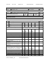
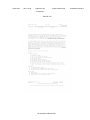
Test item description .................. :
Laptop Computer (OLPC)
Trade Mark .................................... :
OLPC
Manufacturer ................................. :
QUANTA COMPUTER INC
188 WEN-HWA 2ND RD
KUEI SHAN HSIANG
TAOYUAN HSIEN 333 TAIWAN
Model/Type reference ................... :
XO-1, XO-1.5, XO-1.75
Ratings .......................................... :
Model: XO-1
12 Vdc, 1.42 A
Model: XO-1.5, XO-1.75
12 Vdc, 2 A or 13.5Vdc, 1.85A
TRF No.: IEC60950__1B
UL International Demko A/S
E142692-A138-CB-2
Issue Date:
2011-12-06
Page 3 of 45
Report Reference #
E142692-A138-CB-2
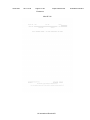
Testing procedure and testing location:
[ ]
CB Testing Laboratory
Testing location / address .............. :
[ ]
Associated CB Test Laboratory
Testing location / address .............. :
Tested by (name + signature) ....... :
Approved by (name + signature) ... :
[x]
[ ]
Testing Procedure: TMP
Tested by (name + signature) ....... :
Scott Chen
Approved by (+ signature) ............. :
Stephanie Henderson
Testing location / address .............. :
QUANTA COMPUTER INC. / 211, WEN HWA 2ND RD.
KUEI SHAN HSIANG, TAOYUAN SHIEN TAIWAN
Testing Procedure: WMT
Tested by (name + signature) ....... :
Witnessed by (+ signature) ............ :
Approved by (+ signature) ............. :
Testing location / address .............. :
[ ]
Testing Procedure: SMT
Tested by (name + signature) ....... :
Approved by (+ signature) ............. :
Supervised by (+ signature) .......... :
Testing location / address .............. :
[ ]
Testing Procedure: RMT
Tested by (name + signature) ....... :
Approved by (+ signature) ............. :
Supervised by (+ signature) .......... :
Testing location / address .............. :
List of Attachments
National Differences (29 pages)
Enclosures (48 pages)
Summary Of Testing
Unless otherwise indicated, all tests were conducted at QUANTA COMPUTER INC. / 211, WEN HWA 2ND
RD. KUEI SHAN HSIANG, TAOYUAN SHIEN TAIWAN.
Tests performed (name of test and test clause)
Input: Single-Phase (1.6.2)
Limited Power Source Measurements (2.5)
TRF No.: IEC60950__1B
UL International Demko A/S
Testing location / Comments
Issue Date:
2011-12-06
Page 4 of 45
Report Reference #
E142692-A138-CB-2
Lithium Battery Reverse Current Measurement (4.3.8)
Heating (4.5.1, 1.4.12, 1.4.13)
Overload of Operator Accessible Connector (5.3.6)
Summary of Compliance with National Differences:
List of countries addressed: AR, AT, AU, BE, CA, CH, CN, CZ, DE, DK, EU, FI, FR, GB, GR, HU, IL, IN, IT,
JP, KE, KR, MY, NL, NO, NZ, PL, SE, SG, SI, SK, US
Copy of Marking Plate - Refer to Enclosure titled Marking Plate for copy.
TRF No.: IEC60950__1B
UL International Demko A/S
Issue Date:
2011-12-06
Page 5 of 45
Report Reference #
E142692-A138-CB-2
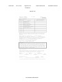
Test item particulars :
Equipment mobility ...............................................:
transportable
Operating condition ..............................................:
continuous
Mains supply tolerance (%) ..................................:
No direct connection
Tested for IT power systems ...............................:
No
IT testing, phase-phase voltage (V) .....................:
N/A
Class of equipment ..............................................:
Class III (supplied by SELV)
Mass of equipment (kg) .......................................:
1.49 (max.)
Protection against ingress of water ......................:
IP 20
Possible test case verdicts:
- test case does not apply to the test object ........... :
N/A
- test object does meet the requirement ................. :
P(Pass)
- test object does not meet the requirement ........... :
F(Fail)
Testing:
Date(s) of receipt of test item ...............................:
2011-11-22
Date(s) of Performance of tests ...........................:
2011-11-22 to 2011-11-24
General remarks:
The test results presented in this report relate only to the object tested.
This report shall not be reproduced, except in full, without the written approval of the testing laboratory.
"(see Enclosure #)" refers to additional information appended to the report.
"(see appended table)" refers to a table appended to the report.
Throughout this report a point is used as the decimal separator.
Manufacturer's Declaration per Sub Clause 6.25 of IECEE 02:
The application for obtaining a CB Test Certificate includes more than one factory and a
declaration form the Manufacturer stating that the sample(s) submitted for evaluation is (are)
representative of the products from each factory has been provided ......
Yes
When differences exist, they shall be identified in the General Product Information section.
Name and address of Factory(ies):
1. TECH-FULL COMPUTER (CHANGSHU) CO LTD,
8 JINZHOU RD, HIGH-TECH INDUSTRIAL PARK, CHANGSHU
ECONOMIC DEVELOPMENT ZONE, CHANGSHU JIANGSU
215500, CHINA
2. TECH-FRONT (SHANGHAI) COMPUTER CO LTD
SONGJIANG EXPORT PROCESSING ZONE,
68 SAN-ZHUANG RD, SHANGHAI 201613, CHINA
3. TECH-PRO (SHANGHAI) COMPUTER CO LTD
SONGJIANG EXPORT PROCESSING ZONE,
6 LANE 58 SANZHUANG RD, SHANGHAI, CHINA
TRF No.: IEC60950__1B
UL International Demko A/S
Issue Date:
2011-12-06
Page 6 of 45
Report Reference #
E142692-A138-CB-2
4. TECH-COM (SHANGHAI) COMPUTER CO LTD
68 SANZHUANG RD,
SONGJIANG EXPORT PROCESSING ZONE,
SHANGHAI 201613, CHINA
GENERAL PRODUCT INFORMATION:
Report Summary
All applicable tests according to the referenced standard(s) have been carried out.
Product Description
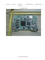
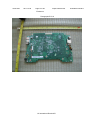
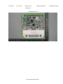
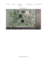
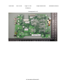
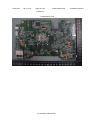
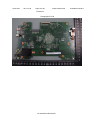
Electronic components are mounted on PWB, which is enclosed by plastic enclosure and accompanied with
three USB ports, one Card Reader.
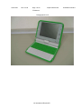
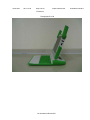
The OLPC XO is a laptop computer system consisting of a (a) laptop computer, (b) direct-plug in power
supply (power adapter) and (c) removable battery pack. The OLPC XO is intended for use as a child
development tool primarily by children five years of age and older. In addition to IEC 60950-1, CSA/UL
60950-1 and EN 60950-1, applicable parts of ASTM F 963, 2007 Edition, Standard Consumer Safety
Specification on Toy Safety, were applied to address use of the product by the intended user group.
Model Differences
Model XO-1.5 is similar to Model XO-1 except for rating, motherboard and model designation.
Model XO-1.75 is similar to Model XO-1.5 except for motherboard and model designation.
Additional Information
- Model: XO-1 => CPU information: AMD / LX700
- Model: XO-1.5, XO-1.75 => CPU information: VIA / C7-M / 1.0 GHz.
- Model: XO-1.5, XO-1.75 => CPU information: AMD / Marvell ARMADA 610 / 1.0 GHz.
- The label is a draft of an artwork for marking plate pending approval by National Certification Bodies and it
shall not be affixed to products prior to such an approval.
- This Report is a re-issue of CB Test Report Reference number E142692-A138-CB-1 dated 2007-11-06, CB
Test Certificate No. DK-12031. During this reissue, the report was also updated to add Model XO-1.75 and
its associated mother board. Based upon the tests conducted and a review of previously conducted testing
it was determined that the product continues to comply with the standards noted.
Technical Considerations
The following "D3" deviations from the Standard were applied for the purposes of US/Canada
certification: Fault test exemption for LPS-supplied circuits (5.3.6)
The product was submitted and evaluated for use at the maximum ambient temperature (Tma)
permitted by the manufacturer‘s specification of: 45°C
TRF No.: IEC60950__1B
UL International Demko A/S
Issue Date:
2011-12-06
Page 7 of 45
Report Reference #
E142692-A138-CB-2
The product was investigated to the following additional standards: 1. UL Standard for Safety for
Electric Toys, UL 696, Ninth Edition, Dated March 15, 1996, Revisions: This Standard contains
revisions through and including June 12, 2006., 2. ASTM F963, 2007 Edition, Standard Consumer
Safety Specification on Toy Safety.
The following circuit locations (with circuit/schematic designation) were investigated as a limited
power source (LPS): USB ports, MIC, Head phone
Technical Considerations - Engineering Considerations: The OLPC XO is a laptop computer system
consisting of a (a) laptop computer, (b) direct-plug in power supply (power adapter) and (c)
removable battery pack. The OLPC XO is intended for use as a child development tool primarily by
children five years of age and older. In addition to IEC 60950-1, CSA/UL 60950-1 and EN 60950-1,
applicable parts of ASTM F 963, 2007 Edition, Standard Consumer Safety Specification on Toy
Safety, were applied to address use of the product by the intended user group.
TRF No.: IEC60950__1B
UL International Demko A/S
Issue Date:
2011-12-06
Page 8 of 45
Report Reference #
E142692-A138-CB-2
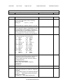
IEC 60950-1
Clause
Requirement + Test
Result - Remark
Verdict
1
GENERAL
Pass
1.5
Components
Pass
1.5.1
General
Pass
Comply with IEC 60950 or relevant component
standard
(see appended table 1.5.1)
Pass
1.5.2
Evaluation and testing of components
Certified components are used
in accordance with their
ratings, certifications and they
comply with applicable parts of
this Standard. Components
not certified are used in
accordance with their ratings
and they comply with
applicable parts of IEC 609501 and the relevant component
Standard. Components, for
which no relevant IECStandard exist, have been
tested under the conditions
occurring in the equipment,
using applicable parts of IEC
60950-1.
Pass
1.5.3
Thermal controls
N/A
1.5.4
Transformers
N/A
1.5.5
Interconnecting cables
1.5.6
Capacitors in primary circuits ................................ :
1.5.7
Double insulation or reinforced insulation bridged
by components
1.5.7.1
General
N/A
1.5.7.2
Bridging capacitors
N/A
1.5.7.3
Bridging resistors
N/A
1.5.7.4
Accessible parts
N/A
1.5.8
Components in equipment for IT power systems
N/A
1.6
Power interface
Pass
1.6.1
AC power distribution systems
N/A
1.6.2
Input current
(see appended table 1.6.2)
Pass
1.6.3
Voltage limit of hand-held equipment
The unit is not a hand-held
equipment.
N/A
1.6.4
Neutral conductor
No AC mains direct
N/A
TRF No.: IEC60950__1B
Interconnecting cables comply
with the relevant requirements
of this standard.
Pass
N/A
Class III product.
UL International Demko A/S
N/A
Issue Date:
2011-12-06
Page 9 of 45
Report Reference #
E142692-A138-CB-2
IEC 60950-1
Clause
Requirement + Test
Result - Remark
Verdict
connection.
1.7
Marking and instructions
1.7.1
Power rating
Pass
The unit did not provided with
means for connection to
mains.
Pass
Rated voltage(s) or voltage range(s) (V) ............... : Optional provided,
12 V dc (XO-1)
12 Vdc or 13.5Vdc (XO-1.5)
Pass
Symbol for nature of supply, for d.c. only .............. : IEC 60417 No. 5031 provided
on marking label (Optional).
Pass
Rated frequency or rated frequency range (Hz) .... :
N/A
Rated current (mA or A) ........................................ : Optional provided,
1.42 A (XO-1)
2 A or 1.85A (XO-1.5, XO1.75)
Pass
Manufacturer's name or trademark or identification Quanta computer Inc., or
mark ....................................................................... : OLPC
Pass
Type/model or type reference ............................... : XO-1, XO-1.5, XO-1.75
Pass
Symbol for Class II equipment only ....................... :
N/A
Other symbols ....................................................... : Additional symbols may be
provided when submitted for
national Approval.
Pass
Certification marks ................................................. : UL, C-UL.
Pass
1.7.2
Safety instructions
Pass
1.7.3
Short duty cycles
N/A
1.7.4
Supply voltage adjustment .................................... : Equipment is designed for
single voltage operation.
N/A
1.7.5
Power outlets on the equipment ............................ : No standard power outlets are
provided.
N/A
1.7.6
Fuse identification .................................................. :
N/A
1.7.7
Wiring terminals
N/A
1.7.7.1
Protective earthing and bonding terminals ............ :
N/A
1.7.7.2
Terminal for a.c. mains supply conductors
N/A
1.7.7.3
Terminals for d.c. mains supply conductors
N/A
1.7.8
Controls and indicators
Pass
1.7.8.1
Identification, location and marking ....................... :
N/A
1.7.8.2
Colours .................................................................. : Controls are only functional
and clearly do not involve
Pass
TRF No.: IEC60950__1B
Operating/safety instructions
made available to the user.
UL International Demko A/S
Issue Date:
2011-12-06
Page 10 of 45
Report Reference #
E142692-A138-CB-2
IEC 60950-1
Clause
Requirement + Test
Result - Remark
Verdict
safety.
1.7.8.3
Symbols according to IEC 60417 .......................... : The stand-by switch is marked
with the correct symbol
according to 60417-1-IEC5009.
Pass
1.7.8.4
Markings using figures ........................................... : Figures are not used for
indicating different positions of
controls.
Pass
1.7.9
Isolation of multiple power sources ....................... :
N/A
1.7.10
IT power distribution systems
N/A
1.7.11
Thermostats and other regulating devices
N/A
1.7.12
Language ............................................................... : May be provided in other
languages upon request from
the manufacturer.
Reviewed only English
markings/instructions.
1.7.13
Durability
All markings provided on UL
Recognized Component labels
suitable for surface they are
applied upon and meet the
durability test.
Pass
1.7.14
Removable parts
No marking is located on
removable part(s).
Pass
1.7.15
Replaceable batteries
The required warning is in the
service manual.
Pass
Language ............................................................... : May be provided in other
languages upon request from
the manufacturer.
Reviewed only English
markings/instructions.
-
-
1.7.16
Operator access with a tool ................................... : No operator access areas
require the use of a tool.
Pass
1.7.17
Equipment for restricted access locations ............. :
N/A
TRF No.: IEC60950__1B
UL International Demko A/S
Issue Date:
2011-12-06
Page 11 of 45
Report Reference #
E142692-A138-CB-2
IEC 60950-1
Clause
Requirement + Test
Result - Remark
Verdict
2
PROTECTION FROM HAZARDS
Pass
2.1
Protection from electric shock and energy hazards
Pass
2.1.1
Protection in operator access areas
All access bare parts are
SELV and no bare TNV
Circuit.
Pass
2.1.1.1
Access to energized parts
No OPERATOR access to
energized parts
Pass
Test by inspection .................................................. : The operator has access to
bare parts of SELV CIRCUITS.
Pass
Test with test finger ............................................... : The test finger was unable to
contact bare hazardous parts,
basic insulation, or ELV
circuits.
Pass
Test with test pin .................................................... : The test pin was unable to
contact bare hazardous parts.
Pass
Test with test probe ............................................... :
N/A
2.1.1.2
Battery compartments ........................................... :
N/A
2.1.1.3
Access to ELV wiring
N/A
Working voltage (V); minimum distance (mm)
through insulation .................................................. :
-
2.1.1.4
Access to hazardous voltage circuit wiring
N/A
2.1.1.5
Energy hazards ..................................................... : There are no hazardous
energy levels in this product.
Pass
2.1.1.6
Manual controls
N/A
2.1.1.7
Discharge of capacitors in equipment
N/A
Time-constant (s); measured voltage (V) .............. :
-
2.1.2
Protection in service access areas
N/A
2.1.3
Protection in restricted access locations
N/A
2.2
SELV circuits
Pass
2.2.1
General requirements
2.2.2
Voltages under normal conditions (V) ................... : All accessible voltages are
less than 42.4 Vp or 60 V dc
and are classified as SELV.
Pass
2.2.3
Voltages under fault conditions (V) ....................... :
N/A
2.2.3.1
Separation by double insulation or reinforced
insulation (method 1)
N/A
2.2.3.2
Separation by earthed screen (method 2)
N/A
2.2.3.3
Protection by earthing of the SELV circuit (method
3)
N/A
TRF No.: IEC60950__1B
Class III unit.
UL International Demko A/S
Pass
Issue Date:
2011-12-06
Page 12 of 45
Report Reference #
E142692-A138-CB-2
IEC 60950-1
Clause
Requirement + Test
2.2.4
Connection of SELV circuits to other circuits ........ : SELV circuits are only
connected to other secondary
circuits.
Pass
2.3
TNV circuits
N/A
2.3.1
Limits
N/A
2.3.2
2.3.3
Result - Remark
Type of TNV circuits .............................................. :
-
Separation from other circuits and from accessible
parts
N/A
Insulation employed ............................................... :
-
Separation from hazardous voltages
N/A
Insulation employed ............................................... :
2.3.4
Verdict
-
Connection of TNV circuits to other circuits
N/A
Insulation employed ............................................... :
-
2.3.5
Test for operating voltages generated externally
N/A
2.4
Limited current circuits
N/A
2.4.1
General requirements
N/A
2.4.2
Limit values
N/A
Frequency (Hz) ...................................................... :
-
Measured current (mA).......................................... :
-
Measured voltage (V) ............................................ :
-
Measured capacitance (mF) .................................. :
-
2.4.3
Connection of limited current circuits to other
circuits
N/A
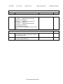
2.5
Limited power sources
Pass
Inherently limited output
Model XO-1, XO-1.5, XO-1.75
Pass
- Following connectors are
data ports only and
compliance with Table 2B
under Maximum V. I. and VA.
measurements:
- MIC
- Head phone
Impedance limited output
N/A
Overcurrent protective device limited output
N/A
Regulating network limited output under normal
operating and single fault condition
TRF No.: IEC60950__1B
See Table 1.5.1 for IC (U56)
specifications.
====================
Model XO-1.5, XO-1.75
UL International Demko A/S
Pass
Issue Date:
2011-12-06
Page 13 of 45
Report Reference #
E142692-A138-CB-2
IEC 60950-1
Clause
Requirement + Test
Result - Remark
Verdict
- See Table 1.5.1 for details.
Regulating network limited output under normal
operating conditions and overcurrent protective
device limited output under single fault condition
N/A
Output voltage (V), output current (A), apparent
The USB (CN4, CN5, CN7)
power (VA): ............................................................ : outputs complied with the
limited power source
requirements
1. USB(CN4, CN5, CN7) three
ports are used one IC U56 to
protector.
Max. Uoc = 4.9 V
Max. Isc = 1.3 A
Max. VA = 5.4VA
-
2. USB CN4 as representative
connector, IC U56 (pin 2, 3 to
pin 6,7 short)
Max. Uoc = 4.94 V
Max. Isc = 1.9 A
Max. VA = 8.4VA
====================
Model XO-1.5, XO-1.75
(See Enclosures /
Miscellaneous Id 7-06 for
details.)
Current rating of overcurrent protective device (A) : --
-
2.6
Provisions for earthing and bonding
N/A
2.6.1
Protective earthing
2.6.2
Functional earthing
N/A
2.6.3
Protective earthing and protective bonding
conductors
N/A
2.6.3.1
General
N/A
2.6.3.2
Size of protective earthing conductors
N/A
Class III unit.
Rated current (A), cross-sectional area (mm2),
AWG ...................................................................... :
2.6.3.3
Size of protective bonding conductors
N/A
N/A
Rated current (A), cross-sectional area (mm2),
AWG ...................................................................... :
-
2.6.3.4
Resistance (Ohm) of earthing conductors and their
terminations, test current (A) ................................. :
N/A
2.6.3.5
Colour of insulation ................................................ :
N/A
TRF No.: IEC60950__1B
UL International Demko A/S
Issue Date:
2011-12-06
Page 14 of 45
Report Reference #
E142692-A138-CB-2
IEC 60950-1
Clause
Requirement + Test
Result - Remark
2.6.4
Terminals
N/A
2.6.4.1
General
N/A
2.6.4.2
Protective earthing and bonding terminals
N/A
Rated current (A), type and nominal thread
diameter (mm) ....................................................... :
Verdict
-
2.6.4.3
Separation of the protective earthing conductor
from protective bonding conductors
N/A
2.6.5
Integrity of protective earthing
N/A
2.6.5.1
Interconnection of equipment
N/A
2.6.5.2
Components in protective earthing conductors and
protective bonding conductors
N/A
2.6.5.3
Disconnection of protective earth
N/A
2.6.5.4
Parts that can be removed by an operator
N/A
2.6.5.5
Parts removed during servicing
N/A
2.6.5.6
Corrosion resistance
N/A
2.6.5.7
Screws for protective bonding
N/A
2.6.5.8
Reliance on telecommunication network or cable
distribution system
N/A
2.7
Overcurrent and earth fault protection in primary circuits
N/A
2.7.1
Basic requirements
N/A
Class III unit.
Instructions when protection relies on building
installation
N/A
2.7.2
Faults not covered in 5.3
N/A
2.7.3
Short-circuit backup protection
N/A
2.7.4
Number and location of protective devices ........... :
N/A
2.7.5
Protection by several devices
N/A
2.7.6
Warning to service personnel ................................ :
N/A
2.8
Safety interlocks
N/A
2.8.1
General principles
2.8.2
Protection requirements
N/A
2.8.3
Inadvertent reactivation
N/A
2.8.4
Fail-safe operation
N/A
2.8.5
Moving parts
N/A
2.8.6
Overriding
N/A
2.8.7
Switches and relays
N/A
2.8.7.1
Contact gaps (mm) ................................................ :
N/A
TRF No.: IEC60950__1B
Class III unit.
UL International Demko A/S
N/A
Issue Date:
2011-12-06
Page 15 of 45
Report Reference #
E142692-A138-CB-2
IEC 60950-1
Clause
Requirement + Test
Result - Remark
2.8.7.2
Overload test
N/A
2.8.7.3
Endurance test
N/A
2.8.7.4
Electric strength test
N/A
2.8.8
Mechanical actuators
N/A
2.9
Electrical insulation
Pass
2.9.1
Properties of insulating materials
2.9.2
Humidity conditioning
Natural rubber, materials
containing asbestos and
hygroscopic materials are not
used as insulation.
Verdict
Pass
N/A
Humidity (%) .......................................................... :
-
Temperature (°C) ................................................... :
-
2.9.3
Grade of insulation
Functional insulation.
N/A
2.10
Clearances, creepage distances and distances through insulation
Pass
2.10.1
General
Pollution Degree 2 applicable.
Pass
2.10.2
Determination of working voltage
Evaluated during separate
certification of the power
supply.
N/A
2.10.3
Clearances
See below.
Pass
2.10.3.1
General
- FUNCTIONAL INSULATION
complied with Sub-clause
5.3.4.
(see appended table 2.10.3
and 2.10.3.4)
Pass
2.10.3.2
Clearances in primary circuit
Evaluated as part of power
supply unit.
N/A
2.10.3.3
Clearances in secondary circuits
See 5.3.4 and appended
tables 2.10.3 & 2.10.4 for
details.
Pass
2.10.3.4
Measurement of transient voltage levels
2.10.4
Creepage distances
N/A
See appended table 2.10.3 &
2.10.4
CTI tests ................................................................ : Material group IIIb assumed;
100 <= CTI < 175.
Pass
-
2.10.5
Solid insulation
N/A
2.10.5.1
Minimum distance through insulation
N/A
2.10.5.2
Thin sheet material
N/A
Number of layers (pcs) .......................................... :
-
Electric strength test .............................................. :
-
TRF No.: IEC60950__1B
UL International Demko A/S
Issue Date:
2011-12-06
Page 16 of 45
Report Reference #
E142692-A138-CB-2
IEC 60950-1
Clause
Requirement + Test
Result - Remark
Verdict
2.10.5.3
Printed boards
N/A
Distance through insulation
N/A
Electric strength test for thin sheet insulating
material .................................................................. :
-
Number of layers (pcs) .......................................... :
N/A
Wound components
N/A
Number of layers (pcs) .......................................... :
N/A
Two wires in contact inside wound component;
angle between 45° and 90° ................................... :
N/A
2.10.6
Coated printed boards
N/A
2.10.6.1
General
N/A
2.10.6.2
Sample preparation and preliminary inspection
N/A
2.10.6.3
Thermal cycling
N/A
2.10.6.4
Thermal ageing (°C) .............................................. :
N/A
2.10.6.5
Electric strength test .............................................. :
-
2.10.6.6
Abrasion resistance test
2.10.5.4
2.10.7
2.10.8
N/A
Electric strength test .............................................. :
-
Enclosed and sealed parts .................................... :
N/A
Temperature T1=T2 = Tma - Tamb +10K (°C) ...... :
N/A
Spacings filled by insulating compound ................ :
N/A
Electric strength test .............................................. :
-
2.10.9
Component external terminations
N/A
2.10.10
Insulation with varying dimensions
N/A
TRF No.: IEC60950__1B
UL International Demko A/S
Issue Date:
2011-12-06
Page 17 of 45
Report Reference #
E142692-A138-CB-2
IEC 60950-1
Clause
Requirement + Test
Result - Remark
3
WIRING, CONNECTIONS AND SUPPLY
Pass
3.1
General
Pass
3.1.1
Current rating and overcurrent protection
All wires/conductors possess
adequate cross-sectional
areas for their intended
application and Internal wiring
are adequately insulated.
Pass
3.1.2
Protection against mechanical damage
The wires are routed away
from sharp edges and parts
which could damage
insulation.
Pass
3.1.3
Securing of internal wiring
The wires are positioned in
such a manner that prevents
excessive strain, loosening of
terminal connections and
damage of conductor
insulation
Pass
3.1.4
Insulation of conductors
The insulation of the individual
conductors is suitable for the
application and the working
voltage. For the insulation
material see 3.1.1.
Pass
3.1.5
Beads and ceramic insulators
N/A
3.1.6
Screws for electrical contact pressure
N/A
3.1.7
Insulating materials in electrical connections
N/A
3.1.8
Self-tapping and spaced thread screws
N/A
3.1.9
Termination of conductors
N/A
10 N pull test
N/A
3.1.10
Sleeving on wiring
N/A
3.2
Connection to an a.c. mains supply or a d.c. mains supply
N/A
3.2.1
Means of connection
N/A
3.2.1.1
Connection to an a.c. mains supply
N/A
3.2.1.2
Connection to a d.c. mains supply
N/A
3.2.2
Multiple supply connections
N/A
3.2.3
Permanently connected equipment
N/A
Class III unit.
Number of conductors, diameter (mm) of cable and
conduits ................................................................. :
Verdict
-
3.2.4
Appliance inlets
N/A
3.2.5
Power supply cords
N/A
TRF No.: IEC60950__1B
UL International Demko A/S
Issue Date:
2011-12-06
Page 18 of 45
Report Reference #
E142692-A138-CB-2
IEC 60950-1
Clause
Requirement + Test
3.2.5.1
AC power supply cords
Result - Remark
Verdict
N/A
Type ....................................................................... :
-
Rated current (A), cross-sectional area (mm²),
AWG ...................................................................... :
-
3.2.5.2
DC power supply cords
N/A
3.2.6
Cord anchorages and strain relief
N/A
Mass of equipment (kg), pull (N) ........................... :
-
Longitudinal displacement (mm) ........................... :
-
3.2.7
Protection against mechanical damage
N/A
3.2.8
Cord guards
N/A
D (mm); test mass (g) ............................................ :
-
Radius of curvature of cord (mm) .......................... :
-
3.2.9
Supply wiring space
N/A
3.3
Wiring terminals for connection of external conductors
N/A
3.3.1
Wiring terminals
N/A
3.3.2
Connection of non-detachable power supply cords
N/A
3.3.3
Screw terminals
N/A
3.3.4
Conductor sizes to be connected
N/A
Class III product
Rated current (A), cord/cable type, cross-sectional
area (mm²) ............................................................. :
3.3.5
Wiring terminal sizes
N/A
Rated current (A), type and nominal thread
diameter (mm) ....................................................... :
-
3.3.6
Wiring terminals design
N/A
3.3.7
Grouping of wiring terminals
N/A
3.3.8
Stranded wire
N/A
3.4
Disconnection from the mains supply
N/A
3.4.1
General requirement
N/A
3.4.2
Disconnect devices
N/A
3.4.3
Permanently connected equipment
N/A
3.4.4
Parts which remain energized
N/A
3.4.5
Switches in flexible cords
N/A
3.4.6
Single-phase equipment and d.c. equipment
N/A
3.4.7
Three-phase equipment
N/A
3.4.8
Switches as disconnect devices
N/A
TRF No.: IEC60950__1B
UL International Demko A/S
Issue Date:
2011-12-06
Page 19 of 45
Report Reference #
E142692-A138-CB-2
IEC 60950-1
Clause
Requirement + Test
3.4.9
Plugs as disconnect devices
N/A
3.4.10
Interconnected equipment
N/A
3.4.11
Multiple power sources
N/A
3.5
Interconnection of equipment
Pass
3.5.1
General requirements
Pass
3.5.2
Types of interconnection circuits ........................... : Interconnection circuits are
SELV CIRCUITS.
Pass
3.5.3
ELV circuits as interconnection circuits
N/A
TRF No.: IEC60950__1B
Result - Remark
UL International Demko A/S
Verdict
Issue Date:
2011-12-06
Page 20 of 45
Report Reference #
E142692-A138-CB-2
IEC 60950-1
Clause
Requirement + Test
Result - Remark
4
PHYSICAL REQUIREMENTS
Pass
4.1
Stability
N/A
Angle of 10°
Based on construction, the test
was deemed not necessary.
Verdict
N/A
Test: force (N) ........................................................ :
N/A
4.2
Mechanical strength
N/A
4.2.1
General
N/A
4.2.2
Steady force test, 10 N
N/A
4.2.3
Steady force test, 30 N
N/A
4.2.4
Steady force test, 250 N
N/A
4.2.5
Impact test
N/A
Fall test
N/A
Swing test
N/A
4.2.6
Drop test
No hazardous parts or in the
reduction of CREEPAGE
DISTANCES or
CLEARANCES within subject
unit.
N/A
4.2.7
Stress relief test
No hazardous parts or in the
reduction of CREEPAGE
DISTANCES or
CLEARANCES within subject
unit.
N/A
4.2.8
Cathode ray tubes
The equipment does not have
any CRT's
N/A
Picture tube separately certified ............................ :
N/A
4.2.9
High pressure lamps
N/A
4.2.10
Wall or ceiling mounted equipment; force (N) ....... :
N/A
4.3
Design and construction
Pass
4.3.1
Edges and corners
4.3.2
Handles and manual controls; force (N) ................ : No hazardous parts or in the
reduction of CREEPAGE
DISTANCES or
CLEARANCES within subject
unit.
N/A
4.3.3
Adjustable controls
N/A
TRF No.: IEC60950__1B
All edges and corners are
judged to be sufficiently well
rounded so as not to constitute
a hazard.
The equipment does not have
a voltage selector.
UL International Demko A/S
Pass
Issue Date:
2011-12-06
Page 21 of 45
Report Reference #
E142692-A138-CB-2
IEC 60950-1
Clause
Requirement + Test
Result - Remark
4.3.4
Securing of parts
No loosening of parts impairing
creepage distances or
clearances over
supplementary or reinforced
insulation is likely to occur.
4.3.5
Connection of plugs and sockets
4.3.6
Direct plug-in equipment
Verdict
Pass
N/A
Not direct plug-in equipment.
N/A
Dimensions (mm) of mains plug for direct plug-in . :
N/A
Torque and pull test of mains plug for direct plug-in;
torque (Nm); pull (N) .............................................. :
N/A
4.3.7
Heating elements in earthed equipment
N/A
4.3.8
Batteries
4.3.9
Oil and grease
N/A
4.3.10
Dust, powders, liquids and gases
N/A
4.3.11
Containers for liquids or gases
N/A
4.3.12
Flammable liquids .................................................. :
N/A
Quantity of liquid (l) ................................................ :
N/A
Flash point (°C) ...................................................... :
N/A
Model XO-1, XO-1.5, XO-1.75
See Critical Components
Table for RTC protected
components details.
4.3.13
Radiation; type of radiation
4.3.13.1
General
N/A
4.3.13.2
Ionizing radiation
N/A
4.3.13.3
The equipment does not
generate ionizing radiation or
contain flammable liquids or
gases.
Pass
N/A
Measured radiation (pA/kg) ................................... :
-
Measured high-voltage (kV) .................................. :
-
Measured focus voltage (kV) ................................. :
-
CRT markings ........................................................ :
-
Effect of ultraviolet (UV) radiation on materials
N/A
Part, property, retention after test, flammability
classification .......................................................... :
N/A
4.3.13.4
Human exposure to ultraviolet (UV) radiation ....... :
N/A
4.3.13.5
Laser (including LEDs)
N/A
4.3.13.6
Laser class ............................................................ :
-
Other types ............................................................ :
N/A
TRF No.: IEC60950__1B
UL International Demko A/S
Issue Date:
2011-12-06
Page 22 of 45
Report Reference #
E142692-A138-CB-2
IEC 60950-1
Clause
Requirement + Test
Result - Remark
Verdict
4.4
Protection against hazardous moving parts
N/A
4.4.1
General
N/A
4.4.2
Protection in operator access areas
N/A
4.4.3
Protection in restricted access locations
N/A
4.4.4
Protection in service access areas
N/A
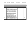
4.5
Thermal requirements
Pass
4.5.1
Maximum temperatures
Operated in the most
unfavorable way of operation
given in the operating
instructions until steady
conditions established. (see
appended table 4.5)
Pass
Normal load condition per Annex L ....................... : Operated in the most
unfavorable way of operation
given in the operating
instructions until steady
conditions established.
Pass
4.5.2
Resistance to abnormal heat
N/A
4.6
Openings in enclosures
Pass
4.6.1
Top and side openings
Pass
Dimensions (mm) .................................................. : No openings.
4.6.2
Bottoms of fire enclosures
Pass
Construction of the bottom .................................... : No openings.
-
4.6.3
Doors or covers in fire enclosures
N/A
4.6.4
Openings in transportable equipment
N/A
4.6.5
Adhesives for constructional purposes
N/A
Conditioning temperature (°C)/time (weeks) ......... :
4.7
Resistance to fire
4.7.1
Reducing the risk of ignition and spread of flame
Pass
Method 1: Selection and
application of components and
materials which minimize the
possibility of ignition and
spread of flame.
Pass
Method 1, selection and application of components
wiring and materials
Pass
Method 2, application of all of simulated fault
condition tests
N/A
4.7.2
Conditions for a fire enclosure
Pass
4.7.2.1
Parts requiring a fire enclosure
TRF No.: IEC60950__1B
A fire enclosure covers all
UL International Demko A/S
Pass
Issue Date:
2011-12-06
Page 23 of 45
Report Reference #
E142692-A138-CB-2
IEC 60950-1
Clause
Requirement + Test
Result - Remark
Verdict
parts.
4.7.2.2
Parts not requiring a fire enclosure
N/A
4.7.3
Materials
Pass
4.7.3.1
General
See below.
Pass
4.7.3.2
Materials for fire enclosures
Equipment is transportable
with mass less than 18 kg. Fire
enclosure material is V-1
minimum.
Pass
4.7.3.3
Materials for components and other parts outside
fire enclosures
Fire enclosure covers all parts.
Pass
4.7.3.4
Materials for components and other parts inside fire PWB are rated minimum V-1
enclosures
and internal plastics are rated
minimum V-2
Pass
4.7.3.5
Materials for air filter assemblies
N/A
4.7.3.6
Materials used in high-voltage components
N/A
TRF No.: IEC60950__1B
UL International Demko A/S
Issue Date:
2011-12-06
Page 24 of 45
Report Reference #
E142692-A138-CB-2
IEC 60950-1
Clause
Requirement + Test
Result - Remark
Verdict
5
ELECTRICAL REQUIREMENTS AND SIMULATED ABNORMAL CONDITIONS
Pass
5.1
Touch current and protective conductor current
N/A
5.1.1
General
N/A
5.1.2
Equipment under test (EUT)
N/A
5.1.3
Test circuit
N/A
5.1.4
Application of measuring instrument
N/A
5.1.5
Test procedure
N/A
5.1.6
Test measurements
N/A
Test voltage (V) ..................................................... :
-
Measured touch current (mA) ................................ :
-
Max. allowed touch current (mA) ........................... :
-
Measured protective conductor current (mA) ........ :
-
Max. allowed protective conductor current (mA) ... :
-
5.1.7
Equipment with touch current exceeding 3.5 mA .. :
N/A
5.1.8
Touch currents to and from telecommunication
networks and cable distribution systems and from
telecommunication networks
5.1.8.1
Limitation of the touch current to a
telecommunication network and a cable distribution
system
N/A
Test voltage (V) ..................................................... :
-
Measured touch current (mA) ................................ :
-
Max. allowed touch current (mA) ........................... :
-
5.1.8.2
Summation of touch currents from
telecommunication networks ................................. :
N/A
5.2
Electric strength
N/A
5.2.1
General
N/A
5.2.2
Test procedure
N/A
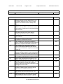
5.3
Abnormal operating and fault conditions
Pass
5.3.1
Protection against overload and abnormal
operation
N/A
5.3.2
Motors
N/A
5.3.3
Transformers
N/A
5.3.4
Functional insulation .............................................. : Functional insulation complies
with the requirements (c).
Pass
5.3.5
Electromechanical components
N/A
TRF No.: IEC60950__1B
No telecommunication
networks and cable distribution
systems.
The equipment does not have
any electromechanical
UL International Demko A/S
N/A
Issue Date:
2011-12-06
Page 25 of 45
Report Reference #
E142692-A138-CB-2
IEC 60950-1
Clause
Requirement + Test
Result - Remark
Verdict
components in the secondary.
5.3.6
Simulation of faults
Connectors overloaded.
Pass
5.3.7
Unattended equipment
5.3.8
Compliance criteria for abnormal operating and
fault conditions
6
CONNECTION TO TELECOMMUNICATION NETWORKS
N/A
6.1
Protection of telecommunication network service persons, and users of other
equipment connected to the network, from hazards in the equipment
N/A
6.1.1
Protection from hazardous voltages
N/A
6.1.2
Separation of the telecommunication network from earth
N/A
6.1.2.1
Requirements
N/A
N/A
No fire, emission of molten
metal or deformation was
noted during the tests.
Pass
Test voltage (V) ..................................................... :
-
Current in the test circuit (mA) ............................... :
-
6.1.2.2
Exclusions.............................................................. :
N/A
6.2
Protection of equipment users from overvoltages on telecommunication networks
N/A
6.2.1
Separation requirements
N/A
6.2.2
Electric strength test procedure
N/A
6.2.2.1
Impulse test
N/A
6.2.2.2
Steady-state test
N/A
6.2.2.3
Compliance criteria
N/A
6.3
Protection of the telecommunication wiring system from overheating
N/A
Max. output current (A) .......................................... :
-
Current limiting method ......................................... :
-
TRF No.: IEC60950__1B
UL International Demko A/S
Issue Date:
2011-12-06
Page 26 of 45
Report Reference #
E142692-A138-CB-2
IEC 60950-1
Clause
Requirement + Test
7
CONNECTION TO CABLE DISTRIBUTION SYSTEMS
N/A
7.1
Protection of cable distribution system service persons, and users of other
equipment connected to the system, from hazardous voltages in the equipment
N/A
7.2
Protection of equipment users from overvoltages
on the cable distribution system
N/A
7.3
Insulation between primary circuits and cable
distribution systems
N/A
7.3.1
General
N/A
7.3.2
Voltage surge test
N/A
7.3.3
Impulse test
N/A
TRF No.: IEC60950__1B
Result - Remark
UL International Demko A/S
Verdict
Issue Date:
2011-12-06
Page 27 of 45
Report Reference #
E142692-A138-CB-2
IEC 60950-1
Clause
Requirement + Test
Result - Remark
Verdict
A
Annex A, TESTS FOR RESISTANCE TO HEAT AND FIRE
N/A
A.1
Flammability test for fire enclosures of movable equipment having a total mass
exceeding 18 kg, and of stationary equipment (see 4.7.3.2)
N/A
A.1.1
Samples ................................................................. :
-
Wall thickness (mm) .............................................. :
-
A.1.2
Conditioning of samples; temperature (°C) ........... :
N/A
A.1.3
Mounting of samples ............................................. :
N/A
A.1.4
Test flame
N/A
A.1.5
Test procedure
N/A
A.1.6
Compliance criteria
N/A
Sample 1 burning time (s) ..................................... :
-
Sample 2 burning time (s) ..................................... :
-
Sample 3 burning time (s) ..................................... :
-
A.2
Flammability test for fire enclosures of movable equipment having a total mass not
exceeding 18 kg, and for material and components located inside fire enclosures
(see 4.7.3.2 and 4.7.3.4)
N/A
A.2.1
Samples, material .................................................. :
-
Wall thickness (mm) .............................................. :
-
A.2.2
Conditioning of samples
N/A
A.2.3
Mounting of samples
N/A
A.2.4
Test flame
N/A
A.2.5
Test procedure
N/A
A.2.6
Compliance criteria
N/A
A.2.7
Sample 1 burning time (s) ..................................... :
-
Sample 2 burning time (s) ..................................... :
-
Sample 3 burning time (s) ..................................... :
-
Alternative test acc. to IEC 60695-2-2, cl. 4, 8
N/A
Sample 1 burning time (s) ..................................... :
-
Sample 2 burning time (s) ..................................... :
-
Sample 3 burning time (s) ..................................... :
-
A.3
Hot flaming oil test (see 4.6.2)
N/A
A.3.1
Mounting of samples
N/A
A.3.2
Test procedure
N/A
A.3.3
Compliance criterion
N/A
TRF No.: IEC60950__1B
UL International Demko A/S
Issue Date:
2011-12-06
Page 28 of 45
Report Reference #
E142692-A138-CB-2
IEC 60950-1
Clause
Requirement + Test
Result - Remark
Verdict
B
Annex B, MOTOR TESTS UNDER ABNORMAL CONDITIONS(see 4.7.2.2 and
5.3.2)
N/A
B.1
General requirements
N/A
Position .................................................................. :
-
Manufacturer ......................................................... :
-
Type ....................................................................... :
-
Rated values .......................................................... :
-
B.2
Test conditions
N/A
B.3
Maximum temperatures
N/A
B.4
Running overload test
N/A
B.5
Locked-rotor overload test
N/A
Test duration (days) ............................................... :
-
Electric strength test: test voltage (V) .................... :
-
B.6
Running overload test for d.c. motors in secondary
circuits
N/A
B.7
Locked-rotor overload test for d.c. motors in secondary circuits
N/A
B.7.1
Test procedure
N/A
B.7.2
Alternative test procedure; test time (h) ................ :
N/A
B.7.3
Electric strength test
N/A
B.8
Test for motors with capacitors
N/A
B.9
Test for three-phase motors
N/A
B.10
Test for series motors
N/A
C
Operating voltage (V) ............................................ :
-
Annex C, TRANSFORMERS (see 1.5.4 and 5.3.3)
N/A
Position .................................................................. :
-
Manufacturer ......................................................... :
-
Type ....................................................................... :
-
Rated values .......................................................... :
-
Method of protection .............................................. :
-
C.1
Overload test
N/A
C.2
Insulation
N/A
Protection from displacement of windings ............. :
N/A
TRF No.: IEC60950__1B
UL International Demko A/S
Issue Date:
2011-12-06
Page 29 of 45
Report Reference #
E142692-A138-CB-2
IEC 60950-1
Clause
Requirement + Test
Result - Remark
D
Annex D, MEASURING INSTRUMENTS FOR TOUCH-CURRENT TESTS
N/A
D.1
Measuring instrument
N/A
D.2
Alternative measuring instrument
N/A
E
Annex E, TEMPERATURE RISE OF A WINDING
N/A
F
Annex F, MEASUREMENT OF CLEARANCES AND CREEPAGE DISTANCES
(see 2.10)
Pass
G
Annex G, ALTERNATIVE METHOD FOR DETERMINING MINIMUM
CLEARANCES
N/A
G.1
Summary of the procedure for determining
minimum clearances
N/A
G.2
Determination of mains transient voltage (V)
N/A
G.2.1
AC mains supply
N/A
G.2.2
DC mains supply
N/A
G.3
Determination of telecommunication network
transient voltage (V) : ............................................ :
N/A
G.4
Determination of required withstand voltage (V) ... :
N/A
G.5
Measurement of transient levels (V) ...................... :
N/A
G.6
Determination of minimum clearances .................. :
N/A
H
ANNEX H, IONIZING RADIATION (see 4.3.13)
N/A
J
Annex J, TABLE OF ELECTROCHEMICAL POTENTIALS (see 2.6.5.6)
N/A
Metal used ............................................................. :
TRF No.: IEC60950__1B
UL International Demko A/S
Verdict
-
Issue Date:
2011-12-06
Page 30 of 45
Report Reference #
E142692-A138-CB-2
IEC 60950-1
Clause
Requirement + Test
K
ANNEX K, THERMAL CONTROLS (see 1.5.3 and 5.3.7)
N/A
K.1
Making and breaking capacity
N/A
K.2
Thermostat reliability; operating voltage (V) .......... :
N/A
K.3
Thermostat endurance test; operating voltage (V) :
N/A
K.4
Temperature limiter endurance; operating voltage
(V) .......................................................................... :
N/A
K.5
Thermal cut-out reliability
N/A
K.6
Stability of operation
N/A
L
Annex L, NORMAL LOAD CONDITIONS FOR SOME TYPES OF ELECTRICAL
BUSINESS EQUIPMENT (see 1.2.2.1 and 4.5.1)
Pass
L.1
Typewriters
N/A
L.2
Adding machines and cash registers
N/A
L.3
Erasers
N/A
L.4
Pencil sharpeners
N/A
L.5
Duplicators and copy machines
N/A
L.6
Motor-operated files
N/A
L.7
Other business equipment
Pass
M
Annex M, CRITERIA FOR TELEPHONE RINGING SIGNALS (see 2.3.1)
N/A
M.1
Introduction
N/A
M.2
Method A
N/A
M.3
Method B
N/A
M.3.1
Ringing signal
N/A
M.3.1.1
Frequency (Hz) ...................................................... :
-
M.3.1.2
Voltage (V) ............................................................. :
-
M.3.1.3
Cadence; time (s), voltage (V) ............................... :
-
M.3.1.4
Single fault current (mA) ........................................ :
-
M.3.2
Tripping device and monitoring voltage ................. :
N/A
M.3.2.1
Conditions for use of a tripping device or a
monitoring voltage
N/A
M.3.2.2
Tripping device
N/A
M.3.2.3
Monitoring voltage (V) ........................................... :
N/A
TRF No.: IEC60950__1B
Result - Remark
UL International Demko A/S
Verdict
Issue Date:
2011-12-06
Page 31 of 45
Report Reference #
E142692-A138-CB-2
IEC 60950-1
Clause
Requirement + Test
Result - Remark
N
Annex N, IMPULSE TEST GENERATORS (see 2.10.3.4, 6.2.2.1, 7.3.2 and
clause G.5)
N/A
N.1
ITU-T impulse test generators
N/A
N.2
IEC 60065 impulse test generator
N/A
P
Annex P, NORMATIVE REFERENCES
Pass
Q
Annex Q, BIBLIOGRAPHY
Pass
R
Annex R, EXAMPLES OF REQUIREMENTS FOR QUALITY CONTROL
PROGRAMMES
N/A
R.1
Minimum separation distances for unpopulated
coated printed boards (see 2.10.6)
N/A
R.2
Reduced clearances (see 2.10.3)
N/A
S
Annex S, PROCEDURE FOR IMPULSE TESTING (see 6.2.2.3)
N/A
S.1
Test equipment
N/A
S.2
Test procedure
N/A
S.3
Examples of waveforms during impulse testing
N/A
T
Annex T, GUIDANCE ON PROTECTION AGAINST INGRESS OF WATER (see
1.1.2)
N/A
............................................................................... :
U
Annex U, INSULATED WINDING WIRES FOR USE WITHOUT INTERLEAVED
INSULATION (see 2.10.5.4)
............................................................................... :
TRF No.: IEC60950__1B
UL International Demko A/S
Verdict
-
N/A
-
Issue Date:
2011-12-06
Page 32 of 45
Report Reference #
E142692-A138-CB-2
IEC 60950-1
Clause
Requirement + Test
Result - Remark
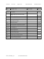
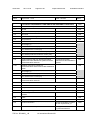
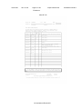
1.5.1
TABLE: list of critical components
Pass
object/part or
Description
01 Connectors
and Receptacles
(secondary
ELV/SELV
circuits)
02 Insulating
Tubing/Sleeving
manufacturer/
trademark
--
type/model
technical data
Metal/Plastic
Copper alloy
pins housed in
bodies of plastic
rated V-2 min.
Various
Various
03 Label
Various
Various
04. Wiring,
internal,
secondary
Various
Various
05 Internal
Various
Plastic Part
Materials
06 Printed Wiring Various
Board
Various
FEP, PTFE,
PVC, TFE,
neoprene,
polyimide or
marked VW-1;
105 degree C,
300V.
60 degree C if
Max. surface
temperature not
specified
FEP, PTFE,
PVC, TFE,
neoprene,
polyimide or
marked VW-1;
min 30 V, 60
degree C, routed
away from
primary
uninsulated live
parts, and unless
insulated for the
highest voltage
involved, from
insulated primary
circuit wiring
Min. V-2
07 Plastic
Material of
Flexible Printed
Wiring
Various
Various
08 Enclosure
CHI MEI
PC-540
CORPORATION
TRF No.: IEC60950__1B
Various
Verdict
standard
(Edition/ year)
UL94, UL498,
UL1977
mark(s) of
1
conformity )
UL, --
UL224
UL, --
UL969
UL, --
UL758
UL, --
UL94, UL746C
UL, --
V-1 min., rated
UL796
min. 105 degree
C
V-2 min. or VTM- UL94, UL746C
2 min. when no
components
mounted on
surface
V-0, 1.5 mm
UL94, UL746C
min., 60 degree
UL, --
UL International Demko A/S
UL, --
UL, ---
Issue Date:
2011-12-06
Page 33 of 45
Report Reference #
E142692-A138-CB-2
IEC 60950-1
Clause
Requirement + Test
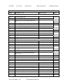
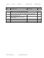
1.5.1
TABLE: list of critical components
object/part or
Description
manufacturer/
trademark
09 Power
Adaptor
(For Rating
12V/1.42A only)
PI Electronics
(H.K.) Ltd.
09a Power
Adaptor
(Alternate)
(For Rating
12V/1.42A only)
09b Power
Adaptor
(Alternate)
(For Rating
12V/1.42A only)
09c Power
Adaptor
(Alternate)
(For Rating
12V/2A only)
09d Power
Adaptor
(Alternate)
(For Rating
13.5V/1.85A
only)
10 Battery pack
Lite-On
Delta
Bestec Power
Electronics Co.,
Ltd
Bestec Power
Electronics Co.,
Ltd
BYD
10a Battery pack Sylva Industries
(Alternate)
Ltd
Rechargeable
Battery Div
10b Battery pack Sylva Industries
(Alternate)
Ltd
Rechargeable
Battery Div
12 Speakers
Various
TRF No.: IEC60950__1B
Result - Remark
type/model
Verdict
Pass
technical data
C, overall 231.0
x 244.0 x 32.8
(with LCD panel)
or 231.0 x 244.0
x 22.0 (without
LCD panel area)
AD5953
INPUT: 100240Vac 560mA
50/60Hz,
OUTPUT: 12Vdc
1.417A.(Class II)
PA-1150-05Q1
I/P: 100240VAC, 0.5A,
50-60HZ; O/P:
12V/1.42A(Class
II)
ADP-17FB A
I/P: 100240VAC, 0.8A,
50-60HZ; O/P:
12V/1.42A(Class
II)
NA0241WAA
I/P: 100-240Vac,
(NAwww1WyA)# 1A, 50/60Hz;
O/P: 12Vdc/2A
(Class II)
standard
(Edition/ year)
mark(s) of
1
conformity )
UL60950-1;
IEC609501:2001
UL, DK-11960
UL60950-1;
IEC609501:2001
UL, NO45038
UL60950-1;
IEC609501:2001
UL, JPTUV020617
UL60950-1, 2nd
Edition;
IEC609501:2001
UL, JPTUV024176
I/P: 100-240Vac,
50/60 Hz, 0.4A;
O/P: 13.5V,
1.85A
UL60950-1, 2nd
Edition;
IEC609501:2001
UL, DK-19690
6.5 V, 3,100
mAh (Li-ion)
6.0 V, 3,000
mAh (Ni-MH)
UL60950-1
UL2054
UL60950-1
UL2054
UL, --
NTA2490
7.3 V, 2800 mAh UL60950-1
(Li-Fe)
UL2054
UL, --
Various
Rated 8 ohm,
max. 1.0 Watt,
max. two
--, --
BTAG250SDFxy
(X=‖-―, y=A-Z or
blank. For
marketing
purpose
CL1
NTA2488
UL International Demko A/S
--
UL, --
Issue Date:
2011-12-06
Page 34 of 45
Report Reference #
E142692-A138-CB-2
IEC 60950-1
Clause
Requirement + Test
Result - Remark
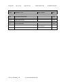
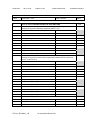
1.5.1
TABLE: list of critical components
Verdict
Pass
object/part or
Description
manufacturer/
trademark
type/model
13 Keyboard
14 LCD panel
Various
Various
Various
Various
15 Printed wiring Various
board, flexible
Following
-Components for
Model XO-1 only
Various
16. Mother board
(for model XO-1)
16-1 Wireless
LAN Card
16-2 R.T.C.
Battery
Various
Various
provided
Min. flame HB
7.5" TFT-LCD
type, LED
backlight
module.
Min V-2 or VTM2, 105 degree C
See Enclosure Id
3-13, 3-14, for
motherboard and
other details.
--
Various
Various
3.3Vdc
Hitachi Maxell
Ltd.
ML1220
UL, --
16-3-1 R.T.C.
Battery
(Alternate)
Matsushita
ML1220
Electric Industrial
Co Ltd.,
Panasonic Corp
Of North
America.
3V, 18 mAh
UL1642
rechargeable
maximum
abnormal
charging current
10mA by multiple
components
Q33, D18 and
R275 rated
1kohm
3V, 17 mAh
UL1642
rechargeable
maximum
abnormal
charging current
10mA by multiple
components
Q33, D18 and
R275 rated
1kohm
2.0-5.5Vdc, 3.5A --
G5282 series
2.0-5.5Vdc, 1.0
A
--
--, --
--
See Enclosure Id -3-24, 3-25, 3-26,
--, --
16-3-2 Protector RICHTEK
IC U56 (for USB
use)
16-3-2a
GMT
Protector IC U56
(for USB use)
(Alternate)
Following
-Components for
TRF No.: IEC60950__1B
--
RT9703 series
technical data
UL International Demko A/S
standard
(Edition/ year)
mark(s) of
1
conformity )
UL94 UL746C
--
UL, ---, --
UL796 UL94
UL, --
--
--, --
--
--, --
--
--, --
UL, --
--, --
Issue Date:
2011-12-06
Page 35 of 45
Report Reference #
E142692-A138-CB-2
IEC 60950-1
Clause
Requirement + Test
Result - Remark
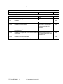
1.5.1
TABLE: list of critical components
Pass
type/model
technical data
Various
Various
3-27 for
motherboard and
other details.
---
--, --
Various
Various
3.3Vdc
--
--, --
HITACHI
MAXELL LTD
ML1220
3 Vdc, Max
Charging
Voltage 12 Vdc;
Max Charging
Current 100 mA
3 Vdc, Max
Charging
Voltage 12 Vdc;
Max Charging
Current 300 mA
UL1642
UL, --
UL1642
UL, --
object/part or
Description
Model XO-1.5
only
manufacturer/
trademark
17 Mother board
(for model XO1.5)
17-1 Wireless
LAN Card
17-2 R.T.C.
Battery
17-2a R.T.C.
Battery
(Alternate)
PANASONIC
ML1220
CORPORATION
, PANASONIC
CORPORATION
OF NORTH
AMERICA
---
17-2-1 RTC
Battery protected
components
Verdict
standard
(Edition/ year)
The RTC battery -is protected by
following:
resistors (R309,
R305/1kohm), a
transistor (Q24)
and a diode
(D20).
2.0-5.5Vdc, 3.5A --
--, --
G5282 series
2.0-5.5Vdc, 1.0
A
--
--, --
--
--, --
--, --
17-3 Protector IC RICHTEK
U5 (for USB use)
17-3a Protector GMT
IC U5 (for USB
use) (Alternate)
Following
-Components for
Model XO-1.75
only
RT9703 series
18. Mother board Various
(for model XO1.75)
18-1 Wireless
Various
Various
See Enclosure Id -3-28, 3-29 for
motherboard and
other details.
Use with Battery
pack :BYD / CL1
only
Use with Adapter
(Bestec) only.
---
Various
3.3Vdc
TRF No.: IEC60950__1B
mark(s) of
1
conformity )
UL International Demko A/S
--
--, --
--, --
Issue Date:
2011-12-06
Page 36 of 45
Report Reference #
E142692-A138-CB-2
IEC 60950-1
Clause
Requirement + Test
Result - Remark
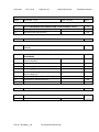
1.5.1
TABLE: list of critical components
Verdict
Pass
object/part or
manufacturer/
Description
trademark
LAN Card
18-2. Protect IC Diodes Inc
U9 (for USB use)
type/model
technical data
AP2171,
AP2161
18-2. R.T.C.
Battery
(alternate)
HITACHI
MAXELL
ENERGY LTD
ML1220
18-2-1. RTC
Battery protect
components
--
--
2.7-5.5Vdc,
UL Subject 2367 UL, -Cont. Current
1.0A, Prot.
Current 2.0A
3 Vdc; Max
UL1642
UL, -Charging
Voltage 12 Vdc;
Max Charging
Current 100 mA
The RTC battery ---, -is protected by
following:
resistors (R35,
R27/1kohm)
(R26/4.7Kohm)
(R23/1.2Kohm),
a transistor (Q1)
and a diode
(D14).
standard
(Edition/ year)
Supplementary information:
1
) Provided evidence ensures the agreed level of compliance. See OD-CB2039.
TRF No.: IEC60950__1B
UL International Demko A/S
mark(s) of
1
conformity )
Issue Date:
2011-12-06
Page 37 of 45
Report Reference #
E142692-A138-CB-2
IEC 60950-1
Clause
Requirement + Test
Result - Remark
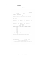
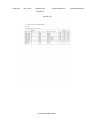
1.6.2
TABLE: electrical data (in normal conditions)
fuse #
--
I rated (A)
1.42
U (V)
12Vdc
P (W)
17.1
I (mA)
1420
--
1.42
12Vdc
17.2
1430
--
1.42
12Vdc
17.1
1420
--
1.42
12Vdc
17.1
1420
--
1.42
12Vdc
17.1
1420
--
1.42
12Vdc
17.1
1420
--
--
6.5Vdc
7.1
1090
--
--
6 Vdc
6.9
1070
---
--
--
--
--
--
1.42
12Vdc
17.1
1440
--
--
7.3 Vdc
11
1500
--
--
--
--
--
--
2
12
23.04
1920
--
2
12
20.88
1740
--
--
6.5
12.22
1880
--
--
6.5
12.48
1920
--
1.85
13.5
22.95
1700
--
1.85
13.5
20.25
1500
TRF No.: IEC60950__1B
Verdict
Pass
I fuse (mA) condition/status
1420
Maximum normal load with empty
battery pack , A and D.
1430
Maximum normal load with empty
battery pack , A and E.
1420
Maximum normal load with empty
battery pack, B and D.
1420
Maximum normal load with empty
battery pack , B and E.
1420
Maximum normal load with empty
battery pack , C and D.
1420
Maximum normal load with empty
battery pack , C and E.
1090
Maximum normal load with system
discharge Battery pack power only
D
1070
Maximum normal load with system
discharge Battery pack power only
E
-Alternate Battery Pack, Sylva
Industries Ltd Rechargeable
Battery Div., Li-Fe Battery Pack,
Model: NTA2490, rated 7.3 Vdc,
2800mAh
1440
Maximum normal load with empty
battery pack, A and F.
1500
Maximum normal load with system
discharge Battery pack power only
F
-Model XO-1.5
(Power Supply: Bestec /
NA0241WAA, Battery pack: BYD /
CL1)
-Max normal load with empty
battery pack.
-System off with empty battery pack
charging mode.
-System off with empty battery pack
charging mode (Measure battery
pack connector)
-Maximum normal load supplied by
battery pack discharge mode
(Measure battery pack connector)
-Maximum normal load with empty
battery pack, G and D.
-Battery charge only,G
UL International Demko A/S
Issue Date:
2011-12-06
Page 38 of 45
Report Reference #
E142692-A138-CB-2
IEC 60950-1
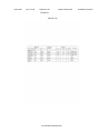
Clause
Requirement + Test
Result - Remark
-
-
-
-
-
-
--
2.0
12
17.76
1480
--
--
2.0
12
16.80
1400
--
--
--
6.99
10.78
1540
--
--
--
6.42
13.48
2100
--
--
1.85
13.5
19.98
1480
--
--
1.85
13.5
17.01
1260
--
--
--
6.99
10.58
1520
--
--
--
6.42
13.48
2100
--
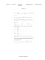
Verdict
Model XO-1.75 with Alternate
Mainboard (Test with Battery Pack
BYD / CL1 and power supply as
noted)
Max normal load.(Bestec /
NA0241WAAA)
Max. normal load with Battery
charge only.(Bestec /
NA0241WAAA,)
System off with empty battery pack
charging mode (Measure battery
pack connector)
Maximum normal load supplied by
battery pack discharge mode
(Battery pack connector)
Max normal load. (Bestec / BTAG250SDFxy)
Max. Normal load with Battery
charge only.(Bestec / BTAG250SDFxy)
System off with empty battery pack
charging mode (Measure battery
pack connector)
Maximum normal load supplied by
battery pack discharge mode
(Battery pack connector)
supplementary information:
Maximum Normal Load: Max. Brightness and contrast and max. volume of speaker, reading/writing between
HDD and playing optical drives, each USB loads 2.5W, charging an empty battery pack Adaptor A. PI adaptor
(Model AD5953LF) B. Delta adaptor (Model ADP-17FB A) C. Lite-on adaptor (Model PA-1150-05Q1) G.
Bestec adaptor (Model BT-AG250SDFxy) Battery pack model : D. BYD Battery Pack (Model CL1) Maximum
Charge Voltage: 7.6 V; Maximum Charge Current: 3100 mA. E. Sylva Industries Ltd Rechargeable Battery Div.,
Battery Pack (Model NTA2488) F. Sylva Industries Ltd Rechargeable Battery Div., Li-Fe Battery Pack, (Model:
NTA2490)
2.10.3 and
2.10.4
TABLE: clearance and creepage distance measurements
clearance cl and creepage
distance dcr at/of:
--
Up
(V)
--
U r.m.s. (V) required cl
cl (mm)
(mm)
---
supplementary information:
Only functional insulation required.
TRF No.: IEC60950__1B
UL International Demko A/S
Pass
required
dcr (mm)
--
dcr
(mm)
--
Issue Date:
2011-12-06
Page 39 of 45
Report Reference #
E142692-A138-CB-2
IEC 60950-1
Clause
Requirement + Test
Result - Remark
2.10.5
TABLE: distance through insulation measurements
distance through insulation di at/of:
Up
(V)
Verdict
N/A
test voltage (V)
required di
(mm)
di
(mm)
supplementary information:
4.5
TABLE: temperature rise measurements
See
--:
test voltage (V)........................................................
below
---:
t1 (°C) ......................................................................
---:
t2 (°C) ......................................................................
Pass
--
--
--
—
--
--
--
—
--
--
--
—
maximum temperature T of part/at:
T (°C)
Normal Condition
1.Amibent
2. RTC battery
3. CPU near PWB
4. Enclosure inside, top section, near CPU
5. Outside enclosure, top section, near CPU
6. Outside enclosure, top section, front panel
LCD
7. Outside enclosure, bottom section, near
mouse control board
8. Outside enclosure, bottom surface, battery
pack (BYD)
9. Outside enclosure, bottom surface, battery
pack (Sylva Industries Ltd Rechargeable
Battery Div.,)
10. Enclosure inside near T1 (Adaptor)
Alternate Battery Pack, Sylva Industries Ltd
Rechargeable Battery Div., Li-Fe Battery Pack,
Model: NTA2490, rated 7.3 Vdc, 2800mAh
1.Amibent
2. RTC battery
3. CPU near PWB
4. Enclosure inside, top section, near CPU
5. Outside enclosure, top section, near CPU
6. Outside enclosure, top section, front panel
TRF No.: IEC60950__1B
Condi
tion 1
(Origi
nal)
25
41
43
39
34
31
Conditio
n1
(Shift to
45)
45
61
63
59
54
51
Conditio
n2
(Original
)
25
34
38
36
32
29
Conditio
n2
(Shift to
45)
45
54
58
56
52
49
--
allowed
Tmax (°C)
--
-------
-100
105
70
95
75
26
46
26
46
--
75
30
50
30
50
--
75
27
47
29
49
--
75
35
Condi
tion 3
(Origi
nal)
25
42
42
39
35
31
55
Conditio
n3
(Shift to
45)
45
62
62
59
55
51
26
Conditio
n4
(Original
)
25
39
44
40
35
30
46
Conditio
n4
(Shift to
45)
45
59
64
60
55
50
---
95
--
-------
-100
105
70
95
75
UL International Demko A/S
Issue Date:
2011-12-06
Page 40 of 45
Report Reference #
E142692-A138-CB-2
IEC 60950-1
Clause
Requirement + Test
Result - Remark
LCD
7. Outside enclosure, bottom section, near
mouse control board
8. Outside enclosure, bottom surface, battery
pack (Sylva Industries Ltd Rechargeable
Battery Div.,)
9. Enclosure inside near T1 (Adaptor)
For Model XO-1.5
Normal Condition
26
46
26
46
--
75
27
47
28
48
--
75
68
-Maximu
m
Normal
Load
(Shift to
45)
32
-Discharg
e battery
pack
only
(Original
)
52
---Discharg -e battery
pack
only
(Shift to
45)
95
---
66.6
64.9
64.2
60.9
57.0
49.9
45.3
49.6
45.0
-Max.
normal
load
(shift to
45)
59.3
59.3
56.3
54.3
53.8
51.3
51.3
45.7
45
40.8
38.5
40.0
37.4
33.0
27.2
23.1
27.0
22.9
-Discharg
e
62.9
60.6
62.1
59.5
55.1
49.3
45.2
49.1
45.0
-Discharg
e (shift
to 45)
------------
105
105
100
105
60
60
60
60
----
38
37.5
33.5
33.1
33
30.5
31.5
25.3
24.7
58.3
57.8
53.8
53.4
53.3
50.8
51.8
45.6
45
----------
105
105
100
60
60
60
60
60
--
48
-Maxi
mum
Norm
al
Load
(Origi
nal)
1.U19 near PWB
45.2
2.U20 near PWB
43.5
3.RTC battery
42.8
4.U17 near PWB
39.5
5.Enclosure inside near U19
35.6
6.Enclosure outside near U19
28.5
7.Enclosure outside near mouse control board 23.9
8.Enclosure outside near battery pack
28.2
9.Ambient
23.6
For Model XO-1.75
-Normal condition
Max.
norm
(See Input Table for Max. Load condition,
al
tested w/battery BYD, Model CLI)
load
1.U19 near PWB
2.U20 near PWB
3.RTC battery
4.Enclosure inside near U19
5.Enclosure outside near U19
6.Enclosure outside near front panel
7.Enclosure outside near mouse control board
8.Enclosure outside near battery pack
9.Ambient
temperature T of winding:
--
39.5
39.5
36.5
34.5
34
31.5
31.5
25.9
25.2
R1 ( )
--
R2 (
--
supplementary information:
Test Condition 1: Maximum normal load 12 Vdc, Duration 15hrs.50mins.
Test Condition 2: Discharge battery pack only, Duration 2hrs.50mins.
Test Condition 3: Maximum normal load 12 Vdc, Duration 15hrs.50mins.
Test Condition 4: Discharge battery pack only, Duration 2hrs.50mins.
TRF No.: IEC60950__1B
Verdict
UL International Demko A/S
)
T (°C)
--
allowed
insulation
Tmax (°C)
class
---
Issue Date:
2011-12-06
Page 41 of 45
Report Reference #
E142692-A138-CB-2
IEC 60950-1
Clause
Requirement + Test
Result - Remark
Verdict
Comments:
The temperatures were measured under worst case normal mode defined in 1.2.2.1 load as described in 1.6.2
at voltages as described in 1.4.5.
With max. ambient temperature specified as 45 degree C, the ore, the maximum temperature rise is calculated
as follows:
Components with:
Max.temp.of 105 degree C(PWB)
Max.temp.of 100 degree C(RTC)
User accessible area:
material is plastic 70 degree C (for Enclosure inside, top section, near CPU)
material is plastic 75 degree C (for Outside enclosure, top section, front panel LCD)
material is plastic 75 degree C (for Outside enclosure, bottom section, near mouse control board)
material is plastic 75 degree C (for Outside enclosure, bottom surface, battery pack (BYD)/ (Sylva Industries
Ltd Rechargeable Battery Div.,))
material is plastic 95 degree C (for Enclosure inside near T1 (Adaptor))
4.5.2
TABLE: ball pressure test of thermoplastics
N/A
—
allowed impression diameter (mm) ........................ :
part
test temperature (°C)
impression diameter
(mm)
supplementary information:
4.7
TABLE: resistance to fire
part
--
Pass
manufacturer of material
--
type of material
--
thickness(mm)
--
flammability
class
--
supplementary information:
Refer to Table 1.5.1 Critical component list.
5.2
TABLE: electric strength tests, impulse tests and voltage surge tests
test voltage applied between:
test voltage (V)
a.c./d.c.
supplementary information:
TRF No.: IEC60950__1B
UL International Demko A/S
N/A
breakdown
Yes / No
Issue Date:
2011-12-06
Page 42 of 45
Report Reference #
E142692-A138-CB-2
IEC 60950-1
Clause
Requirement + Test
Result - Remark
5.3
TABLE: fault condition tests
Verdict
Pass
ambient temperature (°C) ....................................... : 25 degree C
model/type of power supply .................................... : (see appended table 1.5.1)
—
manufacturer of power supply ................................ : (see appended table 1.5.1)
rated markings of power supply ............................. : (see appended table 1.5.1)
—
component fault
No.
---
test voltage
(V)
--
Q33 (pin 1- Short
3)
(Overchargi
ng Test,)
D18 D-S
Short
(Rapid
Dischargin
g Test)
---
12Vdc
RTC
battery
reverse
current test
RTC
battery
reverse
current test
D18
RTC
battery
reverse
current test
Q33 (pin13)
RTC
battery
reverse
current test
Q33 (pin12)
RTC
test time
result
fuse
No.
--
--
14 hrs
30mins.
--
--
--
14 hrs
30mins.
--
--
--
--
--
--
Normal
12Vdc
--
--
--
Clause 4.3.8 -Battery
Overcharge/Discharge
Tests
PA, PB, PC, No hazard.,
Ambient =29 dgree C.
Enclosure inside = 29
degree C
PA, PB, PC, No hazard.,
Ambient =29 dgree C.
Enclosure inside = 29
degree C
4.3.8 Lithium battery
reverse current
measurement test
Charging current is 0 mA
Short
12Vdc
--
--
--
Charging current is 0.56 mA
Short
12Vdc
--
--
--
Charging current is 0 mA
Short
12Vdc
--
--
--
Charging current is 0 mA
Short
12Vdc
--
--
--
Charging current is 0 mA
TRF No.: IEC60950__1B
--
fuse current
(A)
—
UL International Demko A/S
Issue Date:
2011-12-06
Page 43 of 45
Report Reference #
E142692-A138-CB-2
IEC 60950-1
Clause
Requirement + Test
battery
reverse
current test
R275
---
Result - Remark
USB1
(CN7) pin1
Overload
12Vdc
1hrs
--
--
USB1
(CN7)
pin2~4
Overload
12Vdc
--
--
--
USB2
(CN6) pin1
Overload
12Vdc
1hrs
--
--
USB2
Overload
(CN6) pin24
USB3
Overload
(CN4) pin1
12Vdc
--
--
--
12Vdc
1hrs
--
--
USB4(CN4 Overload
) pin2-4
12Vdc
--
--
--
---
---
---
---
---
---
RTC
battery
reverse
current test
RTC
battery
reverse
current test
R309
RTC
battery
reverse
current test
D20
RTC
battery
reverse
current test
Normal
12Vdc
--
--
--
5.3.6 Overload of operator
accessible connector test:
NC,NT
Open circuit voltage=4.9Vdc
Maximum available current
=1210mA
B
Open circuit voltage=0Vdc
Maximum available current
=0mA
NC, NT, Open circuit
voltage=4.9Vdc
Maximum available current
=1220mA
B, Open circuit
voltage=0Vdc ,Maximum
available current =0mA
NC, NT, Open circuit
voltage=4.9Vdc, Maximum
available current =1210mA
B, Open circuit
voltage=0Vdc, Maximum
available current =0mA
For Model XO-1.5
4.3.8 Lithium battery
reverse current
measurement test
Charging current is 0 mA
Short
12Vdc
--
--
--
Charging current is 0 mA
Short
12Vdc
--
--
--
Charging current is 0.56 mA
Short
12Vdc
--
--
--
Charging current is 0 mA
TRF No.: IEC60950__1B
--
--
--
--
Verdict
UL International Demko A/S
Issue Date:
2011-12-06
Page 44 of 45
Report Reference #
E142692-A138-CB-2
IEC 60950-1
Clause
Requirement + Test
Q24 (pin13)
RTC
Short
battery
reverse
current test
R305
-----
Result - Remark
Verdict
12Vdc
--
--
--
Charging current is 0 mA
---
---
---
---
Normal
13.5Vdc
--
--
--
For Model XO-1.75
4.3.8 Lithium battery
reverse current
measurement test
Charging current is 2 mA
Short
Short
Short
13.5Vdc
13.5Vdc
13.5Vdc
----
----
----
Charging current is 4 mA
Charging current is 2 mA
Charging current is 2 mA
Short
Short
--
13.5Vdc
13.5Vdc
--
----
----
----
USB
Overload
(CN11), pin
1
USB
Overload
(CN11), Pin
2-4
USB (CN9) Overload
, pin 1
13.5Vdc
--
--
--
13.5Vdc
--
--
--
Charging current is 3 mA
Charging current is 3 mA
5.3.6 Overload of operator
accessible connector test
NC, NT, Open circuit
voltage=4.95Vdc, Maximum
available current =1310mA
B
13.5Vdc
--
--
--
USB (CN9)
, Pin 2-4
USB
(CN12) ,
pin 1
USB
(CN12) ,
Pin 2-4
MIC (CN3),
Pin 1 to 6
Headphone
(CN4), Pin
1 to 6
Card
reader
(CN19), Pin
4
Overload
13.5Vdc
--
--
--
Overload
13.5Vdc
--
--
--
Overload
13.5Vdc
--
--
--
NC, NT, Open circuit
voltage=4.95Vdc, Maximum
available current =1310mA
B
Overload
13.5Vdc
--
--
--
B
Overload
13.5Vdc
--
--
--
B
Overload
13.5Vdc
--
--
--
C
RTC
battery
reverse
current test
R26
R23
Q1(pin 1-3)
short
D14
R35
--
TRF No.: IEC60950__1B
UL International Demko A/S
NC, NT, Open circuit
voltage=4.95Vdc, Maximum
available current =1310mA
B
Issue Date:
2011-12-06
Page 45 of 45
Report Reference #
E142692-A138-CB-2
IEC 60950-1
Clause
Requirement + Test
Card
Overload
reader
(CN19), Pin
1-3 and 513
Result - Remark
13.5Vdc
--
--
--
Verdict
B
supplementary information:
Comments Key: (BATTERY OVERCHARGE/ DISCHARGE TESTS) PA = There was no cracking, rupturing or
bursting of the battery jacket that could result in user contact with battery electrolyte, PB = There was no
explosion of the battery that could result in a risk of injury to persons, PC = There was no emission of flame or
expulsion of molten metal outside the battery-operated product (COMPONENT FAILURE TEST; ABNORMAL
OPERATION TEST; TRANSFORMER ABNORMAL OPERATION TEST) IP - Internal protection operated (list
component), CT - Constant temperatures were obtained, CD - Components damaged (list damaged
components), NT - Tissue paper remained intact, NC - Cheesecloth remained intact, (OVERLOAD OF
OPERATOR ACCESSIBLE CONNECTOR TEST) B - Circuit measures 0 Volts. C - Less than 12.5mA.
TRF No.: IEC60950__1B
UL International Demko A/S
Issue Date:
2011-12-06
Page 1 of 29
Report Reference #
Enclosure
National Differences
Argentina*
Australia / New Zealand
Austria**
Belgium**
China*
Czech Republic**
Denmark
Finland
France**
Germany
Greece**
Group
Hungary*
India*
Israel*
Italy*
Japan*
Kenya*
Korea
Malaysia*
Netherlands**
Norway
Poland*
Singapore*
Slovakia**
Slovenia*
Sweden
Switzerland**
USA / Canada
United Kingdom
* No National Differences Declared
** Only Group Differences
UL International Demko A/S
E142692-A138-CB-2
Issue Date:
2011-12-06
Page 2 of 29
Report Reference #
E142692-A138-CB-2
IEC 60950-1
SubClause Difference + Test
Result - Remark
Verdict
Australia / New Zealand - Differences to IEC 60950-1:2001, First Edition
1.2.12.201 Addition: POTENTIAL IGNITION SOURCE
Possible fault which can starts a fire if the opencircuit voltage measured across an interruption or
faulty contact exceeds a value of 50 V (peak) a.c.
or d.c. and the product of the peak value of this
voltage and the measured r.m.s. current under
normal operating conditions exceeds 15VA.
Such a faulty contact or interruption in an electrical
connection includes those which may occur in
conductive patterns on printed boards.
Note 201: An electronic protection circuit may be
used to prevent such a fault from becoming a
POTENTIAL IGNITION SOURCE.
Note 202: This definition is from AS/NZS
60065:2003
N/A
1.5.1
Add to the first paragraph: "or the relevant
Australian / New Zealand Standard".
Pass
1.5.2
Add to the first and third dashed items after the
words "IEC Component Standard": "or the relevant
Australian / New Zealand Standard".
Pass
2.1
Delete the Note
3.2.3
Delete Note 2
N/A
3.2.5.1
Substitute for Table 3B: Sizes of Conductors
-------------------------------------------------------------------Rated
Nominal
Current of
cross-sectional
Equipment
area
(A)
(mm²)
-------------------------------------------------------------------0.2 <= 3
0.5 1)
3 <= 7.5
0.75
7.5 <= 10
(0.75) 2) 1.00
10 <= 16
(1,0) 3) 1.5
16 <= 25
2.5
25 <= 32
4
32 <= 40
6
40 <= 63
10
63 <= 80
16
80 <= 100
25
100 <= 125
35
125 <= 160
50
160 <= 190
70
190 <= 230
95
230 <= 260
120
260 <= 300
150
N/A
Delete
UL International Demko A/S
Pass
Issue Date:
2011-12-06
Page 3 of 29
Report Reference #
E142692-A138-CB-2
IEC 60950-1
SubClause Difference + Test
Result - Remark
Verdict
300 <= 340
185
340 <= 400
240
400 <= 460
300
-------------------------------------------------------------------Replace footnote 1) with the following:
1) This nominal cross-sectional area is only
allowed for Class II appliances if the length of the
power supply cord, measured between the point
where the cord or cord guard, enters the appliance,
and the entry to the plug, does not exceed 2 m (0.5
mm² three-core supply flexible cords are not
permitted; see S/NZS 3191).
Delete Note 1.
4.1.201
Addition: Display devices used for television
purposes
Display devices which may be used for television
purposes, with a mass of 7 kg or more, shall
comply with the requirements for stability and
mechanical hazards, including the additional
stability requirements for television received,
specified in AS/NZS 60065.
N/A
4.3.6
Replace the third paragraph: Equipment with a
plug portion, suitable for insertion into a 10 A 3-pin
flat-pin socket-outlet complying with AS/NZS 3112,
shall comply with the requirements in AS/NZS 3112
for equipment with integral pins for insertion into
socket-outlets.
N/A
4.3.13.5
Add the following to the end of the first paragraph:
"or AS/NZS 2211.1"
N/A
4.7
Add after the clause: For alternative resistance to
fire tests, refer to Clause 4.7.201
Pass
4.7.201
Additional after the clause 4.7.3.6:
Resistance to fire - Alternative tests
N/A
4.7.201.1
Addition: General
Parts of non-metallic material shall be resistant to
ignition and spread of fire. This requirement does
not apply to decorative trims, knobs and other parts
unlikely to be ignited or to propagate flames
originating from inside the apparatus, or the
following:
N/A
(a) Components that are contained in an enclosure
having a flammability category of FV-0 according to
AS/NZS 4695.707 and having openings only for the
connecting wires filling the openings completely,
and for ventilation not exceeding 1 mm in width
UL International Demko A/S
Issue Date:
2011-12-06
Page 4 of 29
Report Reference #
E142692-A138-CB-2
IEC 60950-1
SubClause Difference + Test
Result - Remark
Verdict
regardless of length.
(b) The following parts which would contribute
negligible fuel to a fire:
- small mechanical parts, the mass of which does
not exceed 4 g, such as mounting parts, gears,
cams, belts and bearings;
- small electrical components, such as capacitors
with a volume not exceeding 1 750 mm3,
integrated circuits, transistors and optocoupler
packages, if these components are mounted on
material of flammability category FV-1, or better,
according to AS/NZS 4695.707.
NOTE In considering how to minimize propagation
of fire and what ‗small parts‘ are, account should be
taken of the cumulative effect of small parts
adjacent to each other for the possible effect of
propagating fire from one part to another.
Compliance shall be checked by the tests of
4.7.201.2, 4.7.201.3, 4.7.201.4 and 4.7.201.5. For
the base material of printed boards, compliance
shall be checked by the test of 4.7.201.5.
The tests shall be carried out on parts of nonmetallic material which have been removed from
the apparatus. When the glow-wire test is carried
out, the parts shall be placed in the same
orientation as they would be in normal use.
These tests are not carried out on internal wiring.
4.7.201.2
Addition: Testing of non-metallic materials
Parts of non-metallic material shall be subject to
the glow-wire test of AS/NZS 60695.2.11 which
shall be carried out at 550°C.
N/A
Parts for which the glow-wire test cannot be carried
out, such as those made of soft or foamy material,
shall meet the requirements specified in ISO 9772
for category FH-3 material. The glow-wire test shall
be not carried out on parts of material classified at
least FH-3 according to ISO 9772 provided that the
sample tested was not thicker than the relevant
part.
4.7.201.3
Addition: Testing of insulating materials
Parts of insulating material supporting POTENTIAL
IGNITION SOURCES shall be subject to the glowUL International Demko A/S
N/A
Issue Date:
2011-12-06
Page 5 of 29
Report Reference #
E142692-A138-CB-2
IEC 60950-1
SubClause Difference + Test
Result - Remark
wire test of AS/NZS 60695.2.11 which shall be
carried out at 750°C. The test shall be also carried
out on other parts of insulating material which are
within a distance of 3mm of the connection.
NOTE Contacts in components such as switch
contacts are considered to be connections.
For parts which withstand the glow-wire test but
produce a flame, other parts above the connection
within the envelope of a vertical cylinder having a
diameter of 20 mm and a height of 50 mm shall be
subjected to the needle-flame test. However, parts
shielded by a barrier which meets the needle-flame
test shall not be tested. The needle-flame test
shall be made in accordance with AS/NZS
4695.2.2 with the following modifications:
Clause of
AS/NZS 4695.2.2
Change
5 Severities
Replace with:
The duration of application of
the test flame shall be 30 s +/- 1 s.
8
Test procedure
8.2
with:
Replace the first sentence
The specimen shall be
arranged so that the flame can be applied to a
vertical or horizontal edge as shown in the
examples of figure 1.
8.4
apply.
The first paragraph does not
Addition:
If possible, the flame shall be
applied at least 10 mm from a corner.
8.5
Replace with:
The test shall be made on one
specimen. If the specimen does not withswtand
the test, the test may be repeated on two further
specimens, both of which shall then withstand the
test.
10 Evaluation of
Replace with:
UL International Demko A/S
Verdict
Issue Date:
2011-12-06
Page 6 of 29
Report Reference #
E142692-A138-CB-2
IEC 60950-1
SubClause Difference + Test
Result - Remark
Verdict
test results
The duration of burning (tb)
shall not exceed 30 s. However, for printed circuit
boards, it shall not exceed 15 s.
The needle-flame test shall not be carried out on
parts of material classified as V-0 or V-1 according
to IEC 60695-11-10, provided that the sample
tested was not thicker than the relevant part.
4.7.201.4
Addition: Testing in the event of non-extinguishing
material
If parts, other than enclosures, do not withstand the
glow wire tests of 4.7.201.3, by failure to extinguish
within 30 s after the removal of the glow-wire tip,
the needle-flame test detailed in 4.7.201.3 shall be
made on all parts of non-metallic material which
are within a distance of 50 mm or which are likely
to be impinged upon by flame during the tests of
4.7.201.3. Parts shielded by a separate barrier
which meets the needle-flame test need not be
tested.
N/A
NOTE 1 - If the enclosure does not withstand the
glow-wire test the equipment is considered to have
failed to meet the requirements of Clause 4.7.201
without the need for consequential testing.
NOTE 2 - If other parts do not withstand the glowwire test due to ignition of the tissue paper and if
this indicates that burning or glowing particles can
fall onto an external surface underneath the
equipment, the equipment is considered to have
failed to meet the requirements of Clause 4.7.201
without the need for consequential testing.
NOTE 3 - Parts likely to be impinged upon by the
flame are considered to be those within the
envelope of a vertical cylinder having a radius of 10
mm and a height equal to the height of the flame,
positioned above the point of the material
supporting, in contact with, or in close proximity to,
connections.
4.7.201.5
Addition: Testing of printed boards
The base material of printed boards shall be
subjected to the needle-flame test of Clause
4.7.201.3. The flame shall be applied to the edge of
the board where the heat sink effect is lowest when
the board is positioned as in normal use. The flame
shall not be applied to an edge, consisting of
UL International Demko A/S
N/A
Issue Date:
2011-12-06
Page 7 of 29
Report Reference #
E142692-A138-CB-2
IEC 60950-1
SubClause Difference + Test
Result - Remark
Verdict
broken perforations, unless the edge is less than 3
mm from a POTENTIAL IGNITION SOURCE.
The test is not carried out if the
- Printed board does not carry any POTENTIAL
IGNITION SOURCE;
- Base material of printed boards, on which the
available apparent power at a connection exceeds
15 VA operating at a voltage exceeding 50 V and
equal or less than 400 V (peak) a.c. or d.c. under
normal operating conditions, is of flammability
category FV-1 or better according to AS/NZS
4695.707, or the printed boards are protected by
an enclosure meeting the flammability category FV0 according to AS/NZS 4695.707, or made of
metal, having openings only for connecting wires
which fill the openings completely; or
- Base material of printed boards, on which the
available apparatus power at a connection exceeds
15 VA operating at a voltage exceeding 400 V
(peak) a.c. or d.c. under normal operating
conditions, and base material of printed boards
supporting spark gaps which provides protection
against overvoltages, is of flammability category
FV-0 according to AS/NZS 4695.707 or the printed
boards are contained in a metal enclosure, having
openings only for connecting wires which fill the
openings completely.
Compliance shall be determined using the smallest
thickness of the material.
NOTE – Available apparent power is the maximum
apparent power which can be drawn from the
supplying circuit through a resistive load whose
value is chosen to maximise the apparent power
for more than 2 min when the circuit supplied is
disconnected.
6.2.2
Add the following after the first paragraph: In
Australia (not in New Zealand), compliance with
6.2.2 is checked by the tests of both 6.2.2.1 and
6.2.2.2.
N/A
6.2.2.1
Delete Note 2.
Add the following after the first paragraph: In
Australia (not in New Zealand), the electrical
separation is subjected to 10 impulses of
alternating polarity, using the impulse test
generator of Annex N for 10/700µs impulses. The
N/A
UL International Demko A/S
Issue Date:
2011-12-06
Page 8 of 29
Report Reference #
E142692-A138-CB-2
IEC 60950-1
SubClause Difference + Test
Result - Remark
Verdict
interval between successive impulses is 60 s and
the initial voltage, Uc is:
- for 6.2.1a):
7.0 kV for hand-held telephones
and for headsets and
2.5 kV for other equipment and
- for 6.2.1b) and
6.2.1c):
1.5 kV.
NOTE 201 - The 7 kV impulse is to simulate
lightning surges on typical rural and semi-rural
network lines.
NOTE 202 - The value of 2.5 kV for 6.2.1a) was
chosen to ensure adequacy of the insulation
concerned and does not necessarily simulate likely
overvoltages.
6.2.2.2
Delete the Note.
Add the following after the first paragraph: In
Australia (not New Zealand), the a.c. test voltage
is:
- for 6.2.1a)
- for 6.2.1b) and 6.2.1c)
N/A
3 kV; and
1.5 kV
NOTE 201 - Where there are capacitors across the
insulation under test, it is recommended that d.c.
test voltages are used.
NOTE 202 - The 3 kV and 1.5 kV values have been
determined considering the low frequency induced
voltages from the power supply distribution system.
7.2
Add the following before the first paragraph:
Equipment providing functions that fall only within
the scope of AS/NZS 60065 and that incorporate a
PSTN interface, are not required to comply with
this Clause where the only ports provided on the
equipment, in addition to a coaxial cable
connection and a PSTN interface, are audio or
video ports and analogue or data ports not
intended to be used for telecommunication
purposes.
UL International Demko A/S
N/A
Issue Date:
2011-12-06
Page 9 of 29
Report Reference #
E142692-A138-CB-2
IEC 60950-1
SubClause Difference + Test
Result - Remark
Verdict
Denmark - Differences to IEC 60950-1:2001, First Edition
1.2.4.1
Certain types of Class I appliances (see sub-clause
3.2.1.1) may be provided with plug not establishing
earthing continuity when inserted into Danish
socket-outlets.
N/A
1.7.2
Supply cords of Class I equipment, which is
delivered without a plug, must be provided with a
visible tag with the following text:
"Vigtigt !
Lederen med grøn/gul isolation må kun
tilsluttes en klemme mærket
(IEC 417, No. 5019) eller (IEC 417, No. 5017)."
N/A
If essential for the safety of the equipment, the tag
must in addition be provided with a diagram, which
shows the connection of the other conductors, or
be provided with the following text: "For tilslutning
af de øvrige ledere, se medfølgende
installationsvejledning".
1.7.5
Socket-outlets for providing power to other
equipment shall be in accordance with the Heavy
Current Regulations, Section 107-2-D1, Standard
Sheet DK 1-3a, DK 1-5a or DK 1-7a, when used on
Class I equipment. For stationary equipment, the
socket-outlet shall be in accordance with Standard
Sheet DK 1-1b or DK 1-5a.
N/A
1.7.5
Class II equipment shall not be fitted with socketoutlets for providing power to other equipment.
N/A
3.2.1.1
Supply cord of single-phase equipment having a
rated current not exceeding 13 A shall be provided
with a plug according to the Heavy Current
Regulations, Section 107-2-D1.
N/A
Class I equipment provided with socket-outlets with
earth contact or which are intended to be used in
locations where protection against indirect contact
is required according to the wiring rules shall be
provided with a plug in accordance with standard
sheet DK 2-1a or DK 2-5a.
If poly-phase equipment and single-phase
equipment having a rated current exceeding 13 A
is provided with a supply cord with a plug, this plug
shall be in accordance with the Heavy Current
Regulations, Section 107-2-D1 or EN 60309-2.
Finland - Differences to IEC 60950-1:2001, First Edition
UL International Demko A/S
Issue Date:
2011-12-06
Page 10 of 29
Report Reference #
E142692-A138-CB-2
IEC 60950-1
SubClause Difference + Test
Result - Remark
Verdict
1.7.2
Class I Pluggable Equipment Type A intended for
connection to other equipment or a network shall, if
safety relies on connection to protective earth or if
surge suppressors are connected between the
network terminals and accessible parts, have a
marking stating that the equipment must be
connected to an earthed mains socket-outlet. The
marking text shall be:
"Laite on liitettävä suojamaadoituskoskettimilla
varustettuun pistorasiaan"
N/A
6.1.2.1
Add the following text between the first and second
paragraph:
N/A
If this insulation is solid, including insulation
forming part of a component, it shall at least consist
of either
- two layers of thin sheet material, each of which
shall pass the electric strength test below, or
- one layer having a distance through insulation of
at least 0.4 mm, which shall pass the electric
strength test below.
If this insulation forms part of a semiconductor
component (e.g. an optocoupler), there is no
distance through insulation requirement for the
insulation consisting of an insulating compound
completely filling the casing, so that clearances and
creepage distances do not exist, if the component
passes the electric strength test in accordance with
the compliance clause below and in addition:
- passes the tests and inspection criteria of IEC
60950-1, 2.10.8 with an electric strength test of 1.5
kV multiplied by 1.6 (the electric strength test of
2.10.7 shall be performed using 1.5 kV), and
- is subject to routine testing for electric strength
during manufacturing, using a test voltage of 1.5
kV.
It is permitted to bridge this insulation with a
capacitor complying with IEC 60384-14:1993,
subclass Y2.
A capacitor classified Y3 according to IEC 6038414:1993, may bridge this insulation under the
following conditions:
- the insulation requirements are satisfied by
having a capacitor classified Y3 as defined by IEC
60384-14, which in addition to the Y3 testing, is
tested with an impulse test of 2,5 kV defined in EN
60950:2000, subclause 6.2.2.1;
- the additional testing shall be performed on all the
UL International Demko A/S
Issue Date:
2011-12-06
Page 11 of 29
Report Reference #
E142692-A138-CB-2
IEC 60950-1
SubClause Difference + Test
Result - Remark
Verdict
test specimens as described in IEC 60384-14;
- the impulse test of 2,5 kV is to be performed
before the endurance test in IEC 60384-14, in the
sequence of tests as described in IEC 60384-14.
6.1.2.2
The exclusions are applicable for permanently
connected equipment and pluggable equipment
type B and equipment intended to be used in a
restricted access location where equipotential
bonding has been applied, e.g. in a
telecommunication centre, and which has provision
for a permanently connected protective earthing
conductor and is provided with instructions for the
installation of that conductor by a service person.
N/A
7.1
Requirements according to this annex, 6.1.2.1 and
6.1.2.2 apply with the term telecommunication
network in 6.1.2 being replaced by the term cable
distribution system.
N/A
UL International Demko A/S
Issue Date:
2011-12-06
Page 12 of 29
Report Reference #
E142692-A138-CB-2
IEC 60950-1
SubClause Difference + Test
Result - Remark
Verdict
Germany - Differences to IEC 60950-1:2001, First Edition
1.7.12
(Gesetz uber technische Arbeitsmittel
(Geratesicherheitsgesetz) [Law of technical labour
equipment {Equipment safety law}], of 23rd
October 1992, Article 3, 3rd paragraph, 2nd
sentence, together with the "Allgemeine
Verwaltungsvorschrift zur Durchfuhrung des
Zweiten Abschnitts des Geratesicherheitsgesetzes"
[General administrative regulation on the execution
of the Second Section of the Equipment safety
law], of 10th January 1996, article 2, the
paragraph, item 2).
Directions for use with rules to prevent certain
hazards for (among others) maintenance of the
technical labour equipment, also for imported
technical labour equipment shall be written in the
German language.
NOTE: Of this requirement, rules for use even only
by service personnel are not exempted.
N/A
H
(Regulation on protection against hazards by Xray,of 8th January 1987, Article 5 [operation of Xray emission source], clauses 1 to 4)
a) A licence is required by those who operate an
X-ray emission source.
b) A licence in accordance with Cl. 1 is not
required by those who operate an X-ray emission
source on which the electron acceleration voltage
does not exceed 20 kV if
1) the local dose rate at a distance of 0,1 m from
the surface does not exceed 1 µSv/h and
2) it is adequately indicated on the X-ray emission
source that
i) X-rays are generated, and
ii) the electron acceleration voltage must not
exceed the maximum value stipulated by the
manufacturer or importer.
c) A licence in accordance with Cl. 1 is also not
required by persons who operate an X-ray
emission source on which the electron acceleration
voltage exceeds 20 kV if
1) the X-ray emission source has been granted a
type approval, and
2) it is adequately indicated on the X-ray emission
source that
i) X-rays are generated,
ii) the device stipulated by the manufacturer or
importer guarantees that the maximum permissible
local dose rate in accordance with the type
N/A
UL International Demko A/S
Issue Date:
2011-12-06
Page 13 of 29
Report Reference #
E142692-A138-CB-2
IEC 60950-1
SubClause Difference + Test
Result - Remark
approval is not exceeded, and
iii) the electron acceleration voltage must not
exceed the maximum value stipulated by the
manufacturer or importer.
d) Furthermore, a licence in accordance with Cl. 1
is also not required by persons who operate X-ray
emission sources on which the electron
acceleration voltage does not exceed 30 kV if
1) the X-rays are generated only by intrinsically
safe CRTs complying with Enclosure III, No. 6,
2) the values stipulated in accordance with
Enclosure III, No. 6.2 are limited by technical
measures and specified in the device and
3) it is adequately indicated on the X-ray emission
source that the X-rays generated are adequately
screened by the intrinsically safe CRT.
UL International Demko A/S
Verdict
Issue Date:
2011-12-06
Page 14 of 29
Report Reference #
E142692-A138-CB-2
IEC 60950-1
SubClause Difference + Test
Result - Remark
Verdict
Group - Differences to IEC 60950-1:2001, First Edition
2.7.1
Replace the subclause as follows:
Basic requirements
To protect against excessive current, short-circuits
and earth faults in primary circuits, protective
devices shall be included either as integral parts of
the equipment or as parts of the building
installation, subject to the following, a), b) and c):
a) except as detailed in b) and c), protective
devices necessary to comply with the requirements
of 5.3 shall be included as parts of the equipment;
b) for components in series with the mains input to
the equipment such as the supply cord, appliance
coupler, r.f.i. filter and switch, short-circuit and
earth fault protection may be provided by protective
devices in the building installation;
c) it is permitted for pluggable equipment type B or
permanently connected equipment, to rely on
dedicated overcurrent and short-circuit protection in
the building installation, provided that the means of
protection, e.g. fuses or circuit breakers, is fully
specified in the installation instructions.
If reliance is placed on protection in the building
installation, the installation instructions shall so
state, except that for pluggable equipment type A
the building installation shall be regarded as
providing protection in accordance with the rating
of the wall socket outlet.
N/A
2.7.2
Void
N/A
2.10.2
Replace the first line "(see also 1.4.7)" by "(see
also 1.4.8)".
N/A
3.2.3
Delete NOTE 1, and in table 3A delete the conduit
sizes in parentheses.
N/A
3.2.5.1
Replace:
"60245 IEC 53" by "H05 RR-F"
"60227 IEC 52" by "H03 VV-F or H03 VVH2-F"
"60227 IEC 53" by "H05 VV-F or H05 VVH2-F2"
N/A
In table 3B, replace the first four lines by the
following:
Up to and including 6
0.75 ¹
Over 6 up to and including 10 (0.75) ² 1.0
Over 10 up to and including 16 (1.0) ³
1.5
In the Conditions applicable to table 3B, delete the
words "in some countries" in condition ¹.
UL International Demko A/S
Issue Date:
2011-12-06
Page 15 of 29
Report Reference #
E142692-A138-CB-2
IEC 60950-1
SubClause Difference + Test
Result - Remark
Verdict
In Note 1, delete the second sentence.
3.3.4
In table 3D, delete the fourth line: conductor sizes
for 10 to 13 A, and replace with the following:
"Over 10 up to and
including 16
1.5 to 2.5 1.5 to 4"
N/A
Delete the fifth line: conductor sizes for 13 to 16A.
4.3.13.6
Add the following note:
NOTE - Attention is drawn to 1999/519/EC: Council
Recommendation on the limitation of exposure of
the general public to electromagnetic fields 0 Hz to
300 GHz. Standards taking into account this
recommendation are currently under development.
N/A
General
Delete all the "country" notes in the reference
document according to the following list:
1.5.1
Note 2
1.5.8 Note 2
1.6.1
Note
1.7.2 Note 4
1.7.12 Note 2
2.1
Note
2.2.3
Note
2.2.4 Note
2.3.2
Note 2, 7, 8
2.3.3 Note 1, 2
2.3.4
Note 2,3
2.7.1 Note
2.10.3.1 Note 4
3.2.1.1 Note
3.2.3
Note 1, 2
3.2.5.1 Note 2
4.3.6
Note 1,2
4.7.2.2 Note
4.7.3.1 Note 2
6.1.2.1 Note
6.1.2.2 Note
6.2.2 Note
6.2.2.1 Note 2
6.2.2.2 Note
7
Note 4
7.1
Note
G2.1
Note 1, 2
H
Note 2
N/A
H
Replace the last paragraph of this annex by:
At any point 10 cm from the surface of the operator
access area, the dose rate shall not exceed 1
µSv/h (0,1 mR/h) (see note). Account is taken of
the background level.
Replace the notes as follows:
NOTE - These values appear in Directive
96/29/Euratom.
Delete Note 2.
N/A
P
Replace the text of this annex by: See annex ZA
Pass
Q
Replace the title of IEC 61032 by "Protection of
persons and equipment by enclosures - Probes for
verification".
Add the following notes for the standards indicated:
IEC 60127
NOTE Harmonized as EN 60127
(Series) (not modified)
IEC 60269-2-1 NOTE Harmonized as HD
Pass
UL International Demko A/S
Issue Date:
2011-12-06
Page 16 of 29
Report Reference #
E142692-A138-CB-2
IEC 60950-1
SubClause Difference + Test
Result - Remark
Verdict
630.2.1 S4:2000 (modified)
IEC 60529
NOTE Harmonized as EN
60529:1991 (not modified)
IEC 61032
NOTE Harmonized as EN
61032:1998 (not modified)
IEC 61140
NOTE Harmonized as EN
61140:2001 (not modified)
ITU-T Recommendation K.31
NOTE in Europe, the suggested document is EN
50083-1.
Korea - Differences to IEC 60950-1:2001, First Edition
1.5.101
Addition: Plugs for the connection of the apparatus
to the supply mains shall comply with the Korean
requirement (KSC 8305).
N/A
7
Addition: EMC - The apparatus shall comply with
the relevant CISPR standards.
N/A
UL International Demko A/S
Issue Date:
2011-12-06
Page 17 of 29
Report Reference #
E142692-A138-CB-2
IEC 60950-1
SubClause Difference + Test
Result - Remark
Verdict
Norway - Differences to IEC 60950-1:2001, First Edition
1.5.8
Due to the IT power system used (see annex V,
figure V.7), capacitors are required to be rated for
the applicable line-to-line voltage (230 V).
N/A
1.7.2
Class I Pluggable Equipment Type A intended for
connection to other equipment or a network shall, if
safety relies on connection to protective earth or if
surge suppressors are connected between the
network terminals and accessible parts, have a
marking stating that the equipment must be
connected to an earthed mains socket-outlet. The
marking text shall be:
"Apparatet må tilkoples jordet stikkontakt"
N/A
2.2.4
Requirements according to this annex, 1.7.2 and
6.1.2.1 apply.
Pass
2.3.2
Requirements according to this annex, 6.1.2.1
apply.
N/A
2.3.3
Requirements according to this annex, 1.7.2 and
6.1.2.1 apply.
N/A
2.3.4
Requirements according to this annex, 1.7.2 and
6.1.2.1 apply.
N/A
2.10.3.1
Due to the IT power distribution system used (see
annex V, figure V.7), the A.C. mains supply voltage
is considered to be equal to the line-to-line voltage,
and will remain at 230 V in case of a single earth
fault.
N/A
6.1.2.1
Add the following text between the first and second
paragraph:
N/A
If this insulation is solid, including insulation
forming part of a component, it shall at least consist
of either
- two layers of thin sheet material, each of which
shall pass the electric strength test below, or
- one layer having a distance through insulation of
at least 0.4 mm, which shall pass the electric
strength test below.
If this insulation forms part of a semiconductor
component (e.g. an optocoupler), there is no
distance through insulation requirement for the
insulation consisting of an insulating compound
completely filling the casing, so that clearances and
creepage distances do not exist, if the component
passes the electric strength test in accordance with
the compliance clause below and in addition:
UL International Demko A/S
Issue Date:
2011-12-06
Page 18 of 29
Report Reference #
E142692-A138-CB-2
IEC 60950-1
SubClause Difference + Test
Result - Remark
Verdict
- passes the tests and inspection criteria of IEC
60950-1, 2.10.8 with an electric strength test of 1.5
kV multiplied by 1.6 (the electric strength test of
2.10.7 shall be performed using 1.5 kV), and
- is subject to routine testing for electric strength
during manufacturing, using a test voltage of 1.5
kV.
It is permitted to bridge this insulation with a
capacitor complying with IEC 60384-14:1993,
subclass Y2.
A capacitor classified Y3 according to IEC 6038414:1993, may bridge this insulation under the
following conditions:
- the insulation requirements are satisfied by
having a capacitor classified Y3 as defined by IEC
60384-14, which in addition to the Y3 testing, is
tested with an impulse test of 2,5 kV defined in EN
60950:2000, subclause 6.2.2.1;
- the additional testing shall be performed on all the
test specimens as described in IEC 60384-14;
- the impulse test of 2,5 kV is to be performed
before the endurance test in IEC 60384-14, in the
sequence of tests as described in IEC 60384-14.
6.1.2.2
The exclusions are applicable for permanently
connected equipment and pluggable equipment
type B and equipment intended to be used in a
restricted access location where equipotential
bonding has been applied, e.g. in a
telecommunication centre, and which has provision
for a permanently connected protective earthing
conductor and is provided with instructions for the
installation of that conductor by a service person.
N/A
7.1
Requirements according to this annex, 6.1.2.1 and
6.1.2.2 apply with the term telecommunication
network in 6.1.2 being replaced by the term cable
distribution system.
N/A
G.2.1
Due to the IT power distribution system used (see
annex V, figure V.7), the A.C. mains supply voltage
is considered to be equal to the line-to-line voltage,
and will remain at 230 V in case of a single earth
fault.
N/A
UL International Demko A/S
Issue Date:
2011-12-06
Page 19 of 29
Report Reference #
E142692-A138-CB-2
IEC 60950-1
SubClause Difference + Test
Result - Remark
Verdict
Sweden - Differences to IEC 60950-1:2001, First Edition
1.5.1
(Ordinance (1990:944)) Add NOTE: Switches
containing mercury such as thermostats, relays
and level controllers are not allowed.
N/A
1.7.2
Add NOTE: Class I Pluggable Equipment Type A
intended for connection to other equipment or a
network shall, if safety relies on connection to
protective earth or if surge suppressors are
connected between the network terminals and
accessible parts, have a marking stating that the
equipment must be connected to an earthed mains
socket-outlet. The marking text shall be:
"Apparaten skall anslutas till jordat uttag"
N/A
6.1.2.1
Add the following text between the first and second
paragraph:
N/A
If this insulation is solid, including insulation
forming part of a component, it shall at least consist
of either
- two layers of thin sheet material, each of which
shall pass the electric strength test below, or
- one layer having a distance through insulation of
at least 0.4 mm, which shall pass the electric
strength test below.
If this insulation forms part of a semiconductor
component (e.g. an optocoupler), there is no
distance through insulation requirement for the
insulation consisting of an insulating compound
completely filling the casing, so that clearances and
creepage distances do not exist, if the component
passes the electric strength test in accordance with
the compliance clause below and in addition:
- passes the tests and inspection criteria of IEC
60950-1, 2.10.8 with an electric strength test of 1.5
kV multiplied by 1.6 (the electric strength test of
2.10.7 shall be performed using 1.5 kV), and
- is subject to routine testing for electric strength
during manufacturing, using a test voltage of 1.5
kV.
It is permitted to bridge this insulation with a
capacitor complying with IEC 60384-14:1993,
subclass Y2.
A capacitor classified Y3 according to IEC 6038414:1993, may bridge this insulation under the
following conditions:
- the insulation requirements are satisfied by
having a capacitor classified Y3 as defined by IEC
UL International Demko A/S
Issue Date:
2011-12-06
Page 20 of 29
Report Reference #
E142692-A138-CB-2
IEC 60950-1
SubClause Difference + Test
Result - Remark
Verdict
60384-14, which in addition to the Y3 testing, is
tested with an impulse test of 2,5 kV defined in EN
60950:2000, subclause 6.2.2.1;
- the additional testing shall be performed on all the
test specimens as described in IEC 60384-14;
- the impulse test of 2,5 kV is to be performed
before the endurance test in IEC 60384-14, in the
sequence of tests as described in IEC 60384-14.
6.1.2.2
The exclusions are applicable for permanently
connected equipment and pluggable equipment
type B and equipment intended to be used in a
restricted access location where equipotential
bonding has been applied, e.g. in a
telecommunication centre, and which has provision
for a permanently connected protective earthing
conductor and is provided with instructions for the
installation of that conductor by a service person.
N/A
7.1
Requirements according to this annex, 6.1.2.1 and
6.1.2.2 apply with the term telecommunication
network in 6.1.2 being replaced by the term cable
distribution system.
N/A
UL International Demko A/S
Issue Date:
2011-12-06
Page 21 of 29
Report Reference #
E142692-A138-CB-2
IEC 60950-1
SubClause Difference + Test
Result - Remark
Verdict
USA / Canada - Differences to IEC 60950-1:2001, First Edition
1.1
Equipment able to be installed in accordance with
the National Electrical Code ANSI/NFPA 70 and
the Canadian Electrical Code, Part1, and when
applicable, the National Electrical Safety Code,
IEEE C2.
Pass
1.1.1
Equipment able to be installed in accordance with
ANSI/NFPA 75 and NEC Art. 645 unless intended
for use outside of computer room and provided with
such instructions.
Pass
1.1.2
Equipment in wire-line communication facilities
serving high-voltage electric power stations
operating at greater than 1kV are excluded.
N/A
1.1.2
Special requirements apply to equipment intended
for use outdoors.
N/A
1.4.14
For Pluggable Equipment Type A, the protection in
the installation is assumed to be 20 A.
N/A
1.5.1
All IEC standards for components identified in
Annex P.1 replaced by the relevant requirements of
CSA and UL component standards in Annex P.1.
Pass
1.5.1
All IEC standards for components identified in
Annex P.2 alternatively satisfied by the relevant
requirements of CSA and UL component standards
in Annex P.2.
Pass
1.5.5
Interconnecting cables acceptable for the
application regarding voltage, current, temperature,
flammability, mechanical serviceability and the like.
Pass
1.5.5
For other than limited power and TNV circuits, the
type of output circuit identified for output connector.
N/A
1.5.5
External cable assemblies that exceed 3.05 m in
length to be types specified in the NEC and CEC.
N/A
1.5.5
Detachable external interconnecting cables 3.05 m
or less in length and provided with equipment
marked to identify the responsible organization and
the designation for the cable.
N/A
1.5.5
Building wiring and cable for use in ducts, plenums
and other air handling space subject to special
requirements and excluded from scope.
N/A
1.5.5
Telephone line and extension cords and the like
comply with UL 1863 and CSA C22.2 No. 233.
N/A
1.6.1.2
Equipment intended for connection to a d.c. power
(mains) distribution system is subject to special
circuit classification requirements (e.g., TNV-2)
N/A
UL International Demko A/S
Issue Date:
2011-12-06
Page 22 of 29
Report Reference #
E142692-A138-CB-2
IEC 60950-1
SubClause Difference + Test
Result - Remark
Verdict
1.6.1.2
Earthing of d.c. powered equipment provided.
N/A
1.7
Lamp replacement information indicated on
lampholder in operator access area.
N/A
1.7.1
Special marking format for equipment intended for
use on a supply system with an earthed neutral
and more than one phase conductor.
N/A
1.7.1
Equipment voltage rating not higher than rating of
the plug except under special conditions.
N/A
1.7.6
Special fuse replacement marking for operator
accessible fuses.
N/A
1.7.7
Identification of terminal connection of the
equipment earthing conductor.
N/A
1.7.7
Connectors and field wiring terminals for external
Class 2 or Class 3 circuits provided with marking
indicating minimum Class of wiring to be used.
N/A
1.7.7
Marking located adjacent to terminals and visible
during wiring.
N/A
2.1.1
Screw shell of Edison-base lampholder tied to the
neutral conductor.
N/A
2.1.1.1
Bare TNV conductive parts in the interior of
equipment normally protected against contact by a
cover intended for occasional removal are exempt
provided instructions include directions for
disconnection of TNV prior to removal of the cover.
N/A
2.3.1.b
Other telecommunication signaling systems (e.g.,
message waiting) than described in 2.3.1(b) are
subject to M.4.
N/A
2.3.1.b
For TNV-2 and TNV-3 circuits with other than
ringing signals and with voltages exceeding 42.4
Vp or 60 V d.c., the maximum current limit through
a 2000 Ohm or greater resistor with loads
disconnected is 7.1 mA peak or 30 mA d.c. under
normal conditions.
N/A
2.3.1.b
Limits for measurements across 5000 ohm resistor
in the event of a single fault are replaced after 200
ms with the limits of M.3.1.4.
N/A
2.3.2
Enamel coating on signal transformer winding wire
allowed as an alternative to Basic insulation in
specific telecommunication applications when
subjected to special construction requirements and
routine testing.
N/A
2.3.2
In the event of a single fault, the limits of 2.2.3
apply to SELV circuits and accessible conductive
N/A
UL International Demko A/S
Issue Date:
2011-12-06
Page 23 of 29
Report Reference #
E142692-A138-CB-2
IEC 60950-1
SubClause Difference + Test
Result - Remark
Verdict
parts.
2.5
Overcurrent protection device required for Class 2
and Class 3 limiting in accordance with the NEC, or
for a Limited Power Source, not interchangeable
with devices of higher ratings if operator
replaceable.
N/A
2.6
Equipment having receptacles for output a.c. power
connectors generated from an internal separately
derived source have the earthed (grounded) circuit
conductor suitably bonded to earth.
N/A
2.6.3.3
For Pluggable Equipment Type A, if neither a) or b)
are applicable, the current rating of the circuit is
taken as 20 A.
N/A
2.6.3.4
Capacity of connection between earthing terminal
and parts required to be earthed subject to special
conditions based on the current rating of the circuit.
N/A
2.6.3.4
Protective bonding conductors and their terminals
of non-standard constructions (e.g. PWB traces)
evaluated to limited short-circuit test of CSA C22.2
No.0.4.
N/A
2.6.4.1
Field wiring terminals for earthing conductors
suitable for wire sizes (gauge) used in US and
Canada.
N/A
2.7.1
Data for selection of special external branch circuit
overcurrent devices marked on the equipment.
N/A
2.7.1
Standard supply outlets protected by overcurrent
device in accordance with the NEC, and CEC, Part
1.
N/A
2.7.1
Overcurrent protection for individual transformers
that distribute power to other units over branch
circuit wiring.
N/A
2.7.1
Additional requirements for overcurrent protection
apply to equipment provided with panelboards.
N/A
2.7.1
Non-motor-operated equipment requiring special
overcurrent protective device marked with device
rating.
N/A
2.10.5.4
Multi-layer winding wire subject to UL component
wire requirements in addition to 2.10.5.4 and
Annex U.
N/A
3.1.1
Permissible combinations of internal wiring/external
cable sizes for overcurrent and short circuit
protection.
Pass
3.1.1
All interconnecting cables protected against
Pass
UL International Demko A/S
Issue Date:
2011-12-06
Page 24 of 29
Report Reference #
E142692-A138-CB-2
IEC 60950-1
SubClause Difference + Test
Result - Remark
Verdict
overcurrent and short circuit.
3.2
Wiring methods permit connection of equipment to
primary power supply in accordance with the NEC
and CEC, Part 1.
N/A
3.2.1
Permitted use for flexible cords and plugs.
N/A
3.2.1
Flexible cords provided with attachment plug rated
125% of equipment current rating.
N/A
3.2.1
Any Class II equipment provided with 15 or 20 A
standard supply outlets, Edison-base lampholders
or single pole disconnect device provided with a
polarized type attachment plug.
N/A
3.2.1.2
Equipment intended for connection to DC mains
supply power systems complies with special wiring
requirements (e.g., no permanent connection to
supply by flexible cord).
N/A
3.2.1.2
Equipment with one pole of the DC mains supply
connected to both the equipment mains input
terminal and the main protective earthing terminal
provided with special instructions and construction
provisions for earthing
N/A
3.2.1.2
Equipment with means for connecting supply to
earthing electrode conductor has no switches or
protective devices between supply connection and
earthing electrode connection.
N/A
3.2.1.2
Special markings and instructions for equipment
with provisions to connect earthed conductor of a
DC supply circuit to earthing conductor at the
equipment.
N/A
3.2.1.2
Special markings and instructions for equipment
with earthed conductor of a DC supply circuit
connected to the earthing conductor at the
equipment.
N/A
3.2.1.2
Terminals and leads provided for permanent
connection of DC powered equipment to supply
marked to indicate polarity if reverse polarity may
result in a hazard.
N/A
3.2.3
Permanently connected equipment has provision
for connecting and securing a field wiring system
(i.e. conduit, or leads etc.) per the NEC and CEC,
Part 1.
N/A
3.2.3
Permanently connected equipment may have
terminals or leads not smaller than No. 18 AWG
(0.82 mm²) and not less than 152 mm in length for
N/A
UL International Demko A/S
Issue Date:
2011-12-06
Page 25 of 29
Report Reference #
E142692-A138-CB-2
IEC 60950-1
SubClause Difference + Test
Result - Remark
Verdict
connection of field installed wiring.
3.2.3
If supply wires exceed 60 °C, marking indicates
use of 75 °C or 90 °C wiring for supply connection
as appropriate.
N/A
3.2.3
Equipment compatible with suitable trade sizes of
conduits and cables.
N/A
3.2.5
Length of power supply cord limited to between 1.5
and 4.5 m unless shorter length used when
intended for a special installation.
N/A
3.2.5
Conductors in power supply cords sized according
to NEC and CEC, Part I.
N/A
3.2.5
Power supply cords and cord sets incorporate
flexible cords suitable for the particular application.
N/A
3.2.6
Strain relief provided for non-detachable
interconnecting cables not supplied by a limited
power source.
N/A
3.2.9
Adequate wire bending space and volume of field
wiring compartment required to properly make the
field connections.
N/A
3.2.9
Equipment intended solely for installation in
Restricted Access Locations using low voltage d.c.
systems may not need provision for connecting and
securing a field wiring system. A method of
securing wiring or instructions provided to ensure
the wiring is protected from abuse.
N/A
3.3
Field wiring terminals provided for interconnection
of units for other then LPS or Class 2 circuits also
comply with 3.3.
N/A
3.3
Interconnection of units by LPS or Class 2
conductors may have field wiring connectors other
than those specified in 3.3 if wiring is reliably
separated.
N/A
3.3.1
Terminals for the connection of neutral conductor
identified by a distinctive white marking or other
equally effective means.
N/A
3.3.3
Wire binding screw terminal permitted for
connection of No. 10 AWG (5.3 mm²) or smaller
conductor if provided with upturned lugs, cupped
washer or equivalent retention.
N/A
3.3.4
Terminals accept wire sizes (gauge) used in the
U.S. and Canada.
N/A
3.3.4
Terminals accept current-carrying conductors rated
125% of the equipment current rating.
N/A
UL International Demko A/S
Issue Date:
2011-12-06
Page 26 of 29
Report Reference #
E142692-A138-CB-2
IEC 60950-1
SubClause Difference + Test
Result - Remark
Verdict
3.3.6
Field wiring terminals marked to indicate the
material(s) of the conductor appropriate for the
terminals used.
N/A
3.3.6
Connection of an aluminum conductor not
permitted to terminal for equipment earthing
conductor.
N/A
3.3.6
Field wiring connections made through the use of
suitable pressure connectors (including set screw
type), solder lugs or splices to flexible leads.
N/A
3.4.2
Separate motor control device(s) required for cordconnected equipment rated more than 12 A, or with
motor rated more than 1/3 hp or more than 120 V.
N/A
3.4.8
Vertically mounted disconnect devices oriented so
up position of handle is "on".
N/A
3.4.11
For computer-room applications, equipment with
battery systems capable of supplying 750 VA for 5
min require battery disconnect means.
N/A
4.2.8.1
Special opening restrictions for enclosures around
CRTs with face dimension of 160 mm or more.
N/A
4.2.9
Compartment housing high-pressure lamp marked
to indicate risk of explosion.
N/A
4.3.2
Loading test for equipment with handle(s) used to
support more than 9 kg tested at four times the
weight of the unit.
N/A
4.3.6
In addition to the IEC requirements, Direct Plug-in
Equipment complies with UL 1310 or CSA 223
mechanical assembly requirements.
N/A
4.3.12
The maximum quantity of flammable liquid stored
in equipment complies with ANSI/NFPA 30(Table
NAE.6).
N/A
4.3.12
Equipment using replenishable liquids marked to
indicate type of liquid to be used.
N/A
4.3.13.2
Equipment that produces x-radiation and does not
comply with 4.3.12 under all conditions of servicing
marked to indicate the presence of radiation where
readily visible.
N/A
4.3.13.5
Requirements contained in the applicable national
codes and regulations apply to lasers (21 CFR
1040 and REDR C1370).
N/A
4.7
Automated information storage equipment intended
to contain more than 0.76 m³ of combustible media
requires provision for automatic sprinklers or a
gaseous agent extinguishing system.
N/A
UL International Demko A/S
Issue Date:
2011-12-06
Page 27 of 29
Report Reference #
E142692-A138-CB-2
IEC 60950-1
SubClause Difference + Test
Result - Remark
Verdict
4.7.3.1
Equipment for use in environmental air space other
than ducts or plenums provided with metal
enclosure or with non-metallic enclosure having
adequate fire-resistance and low smoke producing
characteristics. Low smoke-producing
characteristics evaluated according to UL 2043.
Equipment for installation in space used for
environmental air as described in Sec. 300-22(c) of
the NEC provided with instructions indicating
suitability for installation in such locations.
N/A
4.7.3.1
Flame spread rating for external surface of
combustible material with exposed area greater
than 0.93 m² or a single dimension greater than 1.8
m; 50 or less for computer room applications or
200 or less for other applications.
N/A
4.7.3.4
Wire marked "VW-1" or "FT-1" considered
equivalent.
Pass
5.1.8.2
Special earthing provisions and instructions for
equipment with high touch current due to
telecommunication network connections.
N/A
5.1.8.3
Touch current due to ringing voltage for equipment
containing telecommunication network leads.
N/A
5.3.6
Overloading of SELV connectors and printed wiring
board receptacles accessible to the operator.
Pass
5.3.6
Tests interrupted by opening of a component
repeated two additional times.
N/A
5.3.8.1
Test interrupted by opening of wire or trace subject
to certain conditions.
N/A
6
Specialized instructions provided for telephones
that may be connected to a telecommunications
network.
N/A
6
Marking identifying function of telecommunication
type connectors not used for connection to a
telecommunication network.
N/A
6.2.1
Special requirements for enameled wiring used as
electrical separation provided between parts
connected to telecommunication network and
telecommunication circuitry intentionally isolated
from network.
N/A
6.2.1
Digital line termination equipment (e.g., NCTE)
subject to separation requirements.
N/A
6.3
Equipment remotely powered over
telecommunication wiring systems provided with
N/A
UL International Demko A/S
Issue Date:
2011-12-06
Page 28 of 29
Report Reference #
E142692-A138-CB-2
IEC 60950-1
SubClause Difference + Test
Result - Remark
Verdict
specialized markings adjacent to the connection.
6.3
Overcurrent protection incorporated into equipment
to provide power over telecommunication wiring
system not interchangeable with devices of higher
ratings if operator replaceable.
N/A
6.4
Additional requirements for equipment intended for
connection to a telecommunication network using
cable subject to overvoltage from power line
failures (Fig. 6C).
N/A
6.4
Where 26 AWG line cord required by Fig. 6C,
either the cord is provided with the equipment or
described in the safety instructions.
N/A
6.5
Acoustic pressure from an ear piece less than 136
dBA for short duration disturbances, and less than
125 dBA for handsets, 118 dBA for headsets, and
121 dBA for insert earphones, for long duration
disturbances.
N/A
7
Equipment associated with the cable distribution
system may need to be subjected to applicable
parts of Chapter 8 of the NEC.
N/A
H
Ionizing radiation measurements made under
single fault conditions in accordance with the
requirements of the Code of Federal Regulations
21 CFR 1020 and the Canadian Radiation Emitting
Devices Act, REDR C1370.
N/A
M.2
Continuous ringing signals evaluated to Method A
subjected to special accessibility considerations.
N/A
M.4
Special requirements for message waiting and
similar telecommunications signals.
N/A
NAC
Equipment intended for use with a generic
secondary protector marked with suitable
instructions.
N/A
NAC
Equipment intended for use with a specific primary
or secondary protector marked with suitable
instructions.
N/A
NAF
Household/Home Office Document Shredders
N/A
NAF.1.7
Markings and instructions alert the user to key
safety considerations related to use of shredders,
including not intended to be used by children, avoid
touching document feed opening, avoid clothes
and hair entanglement, and avoid aerosol products.
N/A
NAF.2.8.3
Safety interlock cannot be inadvertently activated
by the articulated accessibility probe (figure
N/A
UL International Demko A/S
Issue Date:
2011-12-06
Page 29 of 29
Report Reference #
E142692-A138-CB-2
IEC 60950-1
SubClause Difference + Test
Result - Remark
Verdict
NAF.1).
NAF.3.4
Provided with an isolating switch complying with
3.4.2, including 3 mm contact gap, with appropriate
markings associated with the switch.
N/A
NAF.4.4
Hazardous moving parts are not accessible to the
user, as determined using the articulated
accessibility probe (figure NAF.1) and the
accessibility probe/wedge (figures NAF.2/NAF.3).
N/A
United Kingdom - Differences to IEC 60950-1:2001, First Edition
2.6.3.3
The current rating of the circuit shall be taken as 13
A, not 16 A.
N/A
2.7.1
To protect against excessive currents and shortcircuits in the primary circuit of direct plug-in
equipment, protective device shall be included as
integral parts of the direct plug-in equipment.
N/A
3.2.1.1
Apparatus which is fitted with a flexible cable or
cord and is designed to be connected to a mains
socket conforming to BS 1363 by means of that
flexible cable or cord and plug, shall be fitted with a
"standard plug" in accordance with Statutory
Instrument 1768: 1994 - The Plugs and Sockets
etc. (Safety) Regulations 1994, unless exempted
by those regulations.
N/A
NOTE: "Standard plug" is defined in SI 1768: 1994
and essentially means an approved plug
conforming to BS 1363 or an approved conversion
plug.
3.2.5.1
A power supply cord with conductor of 1.25 mm² is
allowed for equipment with a rated current over
10A and up to and including 13A.
N/A
3.3.4
The range of conductor sizes of flexible cords to be
accepted by terminals for equipment with a rated
current of over 10 A up to and including 13 A is
1.25 mm² to 1.5 mm² nominal cross-sectional area.
N/A
4.3.6
The torque test is performed using a socket outlet
complying with BS 1363 and the plug part of Direct
Plug-In Equipment shall be assessed to BS 1363:
Part 1, 12.1, 12.2, 12.3, 12.9, 12.11, 12.12, 12.16
and 12.17, except that the test of 12.17 is
performed at not less than 125 °C.
N/A
UL International Demko A/S
Issue Date:
2011-12-06
Page 1 of 48
Report Reference #
E142692-A138-CB-2
Enclosures
Enclosures
Type
Supplement Id
Description
Photographs
3-06
NB top view
Photographs
3-07
NB front open view
Photographs
3-08
NB left side view
Photographs
3-09
NB right side view
Photographs
3-10
NB bottom view with battery pack A32-V2
Photographs
3-12
NB bottom internal view
Photographs
3-13
PCB top view
Photographs
3-14
PCB bottom view
Photographs
3-24
(XO-1.5) Internal -1
Photographs
3-25
(XO-1.5) Internal -2
Photographs
3-26
(XO-1.5) Motherboard -1
Photographs
3-27
(XO-1.5) Motherboard -2
Photographs
3-28
(XO-1.75) Motherboard-1
Photographs
3-29
(XO-1.75) Motherboard-2
Photographs
3-30
NB bottom internal view(alternate)
Miscellaneous
7-04
Datasheets for UL 696
Miscellaneous
7-05
Datasheets ASTM F963
Miscellaneous
7-06
Table 2.5 - Limited Power Source Measurement (Not for FUS
investigation)
Miscellaneous
7-07
Client Instrument list
Miscellaneous
7-08
Multi-factories Declaration
Marking Plate
13-01
Label (XO-1)
Marking Plate
13-02
Label (XO-1.5)
Marking Plate
13-03
Label (XO-1.5)-Alternate
Marking Plate
13-04
Label (XO-1.75)
Diagrams
Schematics + PWB
Manuals
Licenses
UL International Demko A/S
Issue Date:
2011-12-06
Page 2 of 48
Report Reference #
Enclosures
MarkingPlate ID 13-01
UL International Demko A/S
E142692-A138-CB-2
Issue Date:
2011-12-06
Page 3 of 48
Report Reference #
Enclosures
MarkingPlate ID 13-02
UL International Demko A/S
E142692-A138-CB-2
Issue Date:
2011-12-06
Page 4 of 48
Report Reference #
Enclosures
MarkingPlate ID 13-03
UL International Demko A/S
E142692-A138-CB-2
Issue Date:
2011-12-06
Page 5 of 48
Report Reference #
Enclosures
MarkingPlate ID 13-04
UL International Demko A/S
E142692-A138-CB-2
Issue Date:
2011-12-06
Page 6 of 48
Report Reference #
Enclosures
Photographs ID 3-06
UL International Demko A/S
E142692-A138-CB-2
Issue Date:
2011-12-06
Page 7 of 48
Report Reference #
Enclosures
Photographs ID 3-07
UL International Demko A/S
E142692-A138-CB-2
Issue Date:
2011-12-06
Page 8 of 48
Report Reference #
Enclosures
Photographs ID 3-08
UL International Demko A/S
E142692-A138-CB-2
Issue Date:
2011-12-06
Page 9 of 48
Report Reference #
Enclosures
Photographs ID 3-09
UL International Demko A/S
E142692-A138-CB-2
Issue Date:
2011-12-06
Page 10 of 48
Report Reference #
Enclosures
Photographs ID 3-10
UL International Demko A/S
E142692-A138-CB-2
Issue Date:
2011-12-06
Page 11 of 48
Report Reference #
Enclosures
Photographs ID 3-12
UL International Demko A/S
E142692-A138-CB-2
Issue Date:
2011-12-06
Page 12 of 48
Report Reference #
Enclosures
Photographs ID 3-13
UL International Demko A/S
E142692-A138-CB-2
Issue Date:
2011-12-06
Page 13 of 48
Report Reference #
Enclosures
Photographs ID 3-14
UL International Demko A/S
E142692-A138-CB-2
Issue Date:
2011-12-06
Page 14 of 48
Report Reference #
Enclosures
Photographs ID 3-24
UL International Demko A/S
E142692-A138-CB-2
Issue Date:
2011-12-06
Page 15 of 48
Report Reference #
Enclosures
Photographs ID 3-25
UL International Demko A/S
E142692-A138-CB-2
Issue Date:
2011-12-06
Page 16 of 48
Report Reference #
Enclosures
Photographs ID 3-26
UL International Demko A/S
E142692-A138-CB-2
Issue Date:
2011-12-06
Page 17 of 48
Report Reference #
Enclosures
Photographs ID 3-27
UL International Demko A/S
E142692-A138-CB-2
Issue Date:
2011-12-06
Page 18 of 48
Report Reference #
Enclosures
Photographs ID 3-28
UL International Demko A/S
E142692-A138-CB-2
Issue Date:
2011-12-06
Page 19 of 48
Report Reference #
Enclosures
Photographs ID 3-29
UL International Demko A/S
E142692-A138-CB-2
Issue Date:
2011-12-06
Page 20 of 48
Report Reference #
Enclosures
Photographs ID 3-30
UL International Demko A/S
E142692-A138-CB-2
Issue Date:
2011-12-06
Page 21 of 48
Report Reference #
Enclosures
Misc ID 7-04
UL International Demko A/S
E142692-A138-CB-2
Issue Date:
2011-12-06
Page 22 of 48
Report Reference #
Enclosures
Misc ID 7-04
UL International Demko A/S
E142692-A138-CB-2
Issue Date:
2011-12-06
Page 23 of 48
Report Reference #
Enclosures
Misc ID 7-04
UL International Demko A/S
E142692-A138-CB-2
Issue Date:
2011-12-06
Page 24 of 48
Report Reference #
Enclosures
Misc ID 7-04
UL International Demko A/S
E142692-A138-CB-2
Issue Date:
2011-12-06
Page 25 of 48
Report Reference #
Enclosures
Misc ID 7-04
UL International Demko A/S
E142692-A138-CB-2
Issue Date:
2011-12-06
Page 26 of 48
Report Reference #
Enclosures
Misc ID 7-04
UL International Demko A/S
E142692-A138-CB-2
Issue Date:
2011-12-06
Page 27 of 48
Report Reference #
Enclosures
Misc ID 7-04
UL International Demko A/S
E142692-A138-CB-2
Issue Date:
2011-12-06
Page 28 of 48
Report Reference #
Enclosures
Misc ID 7-05
UL International Demko A/S
E142692-A138-CB-2
Issue Date:
2011-12-06
Page 29 of 48
Report Reference #
Enclosures
Misc ID 7-05
UL International Demko A/S
E142692-A138-CB-2
Issue Date:
2011-12-06
Page 30 of 48
Report Reference #
Enclosures
Misc ID 7-05
UL International Demko A/S
E142692-A138-CB-2
Issue Date:
2011-12-06
Page 31 of 48
Report Reference #
Enclosures
Misc ID 7-05
UL International Demko A/S
E142692-A138-CB-2
Issue Date:
2011-12-06
Page 32 of 48
Report Reference #
Enclosures
Misc ID 7-05
UL International Demko A/S
E142692-A138-CB-2
Issue Date:
2011-12-06
Page 33 of 48
Report Reference #
Enclosures
Misc ID 7-05
UL International Demko A/S
E142692-A138-CB-2
Issue Date:
2011-12-06
Page 34 of 48
Report Reference #
Enclosures
Misc ID 7-05
UL International Demko A/S
E142692-A138-CB-2
Issue Date:
2011-12-06
Page 35 of 48
Report Reference #
Enclosures
Misc ID 7-05
UL International Demko A/S
E142692-A138-CB-2
Issue Date:
2011-12-06
Page 36 of 48
Report Reference #
Enclosures
Misc ID 7-05
UL International Demko A/S
E142692-A138-CB-2
Issue Date:
2011-12-06
Page 37 of 48
Report Reference #
Enclosures
Misc ID 7-05
UL International Demko A/S
E142692-A138-CB-2
Issue Date:
2011-12-06
Page 38 of 48
Report Reference #
Enclosures
Misc ID 7-05
UL International Demko A/S
E142692-A138-CB-2
Issue Date:
2011-12-06
Page 39 of 48
Report Reference #
Enclosures
Misc ID 7-05
UL International Demko A/S
E142692-A138-CB-2
Issue Date:
2011-12-06
Page 40 of 48
Report Reference #
Enclosures
Misc ID 7-05
UL International Demko A/S
E142692-A138-CB-2
Issue Date:
2011-12-06
Page 41 of 48
Report Reference #
Enclosures
Misc ID 7-05
UL International Demko A/S
E142692-A138-CB-2
Issue Date:
2011-12-06
Page 42 of 48
Report Reference #
Enclosures
Misc ID 7-05
UL International Demko A/S
E142692-A138-CB-2
Issue Date:
2011-12-06
Page 43 of 48
Report Reference #
Enclosures
Misc ID 7-05
UL International Demko A/S
E142692-A138-CB-2
Issue Date:
2011-12-06
Page 44 of 48
Report Reference #
Enclosures
Misc ID 7-05
UL International Demko A/S
E142692-A138-CB-2
Issue Date:
2011-12-06
Page 45 of 48
Report Reference #
Enclosures
Misc ID 7-06
UL International Demko A/S
E142692-A138-CB-2
Issue Date:
2011-12-06
Page 46 of 48
Report Reference #
Enclosures
Misc ID 7-06
UL International Demko A/S
E142692-A138-CB-2
Issue Date:
2011-12-06
Page 47 of 48
Report Reference #
Enclosures
Misc ID 7-07
UL International Demko A/S
E142692-A138-CB-2
Issue Date:
2011-12-06
Page 48 of 48
Report Reference #
Enclosures
Misc ID 7-08
UL International Demko A/S
E142692-A138-CB-2