1
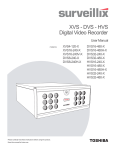
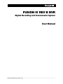
FUSION IV REV B NVR
Digital Recording and Transmission System
User Manual
_______________________________________________________________________________________________________
Document 800-03703V1 Rev B 10/11
Revisions
Issue
Date
Revisions
A
July 2011
Based on 800-03703-A; updated for Rev B hardware and version 4.5
software
B
October 2011
Updated user notes
________________________________________________________________________________________________________
2
Fusion IV NVR User Guide
FCC Compliance Statement
INFORMATION TO THE USER: THIS EQUIPMENT HAS BEEN TESTED AND FOUND TO COMPLY
WITH THE LIMITS FOR A CLASS B DIGITAL DEVICE, PERSUANT TO PART 15 OF THE FCC
RULES. THESE LIMITS ARE DESIGNED TO PROVIDE REASONABLE PROTECTION AGAINST
HARMFUL INTERFERENCE IN A RESIDENTIAL INSTALLATION. THIS EQUIPMENT GENERATES,
USES AND CAN RADIATE RADIO FREQUENCY ENERGY AND, IF NOT INSTALLED AND USED IN
ACCORDANCE WITH THE INSTRUCTIONS, MAY CAUSE HARMFUL INTERFEENCE TO RADIO
COMMUNICATIONS. HOWEVER THERE IS NO GUARANTEE THAT INTERFERENCE WILL NOT
OCCUR IN A PARTICULAR INSTALLATION. IF THIS EQUIPMENT DOES CAUSE HARMFUL
INTERFERENCE TO RADIO OR TELEVISION RECEPTION, WHICH CAN BE DETERMINED BY
TURNING THE EQUIPMENT OFF AND ON, THE USER IS ENCOURAGED TO TRY TO CORRECT
THE INTERFERENCE BY ONE OR MORE OF THE FOLLOWING MEASURES:
•
REORIENT OR RELOCATE THE RECEIVING ANTENNA.
•
INCREASE THE SEPARATION BETWEEN THE EQUIPMENT AND RECEIVER.
•
CONNECT THE EQUIPMENT TO AN OUTLET ON A CIRCUIT DIFFERENT FROM THAT TO
WHICH THE RECEIVER IS CONNECTED.
•
CONSULT THE DEALER OR AN EXPERIENCED RADIO/TV TECHNICIAN FOR HELP.
CAUTION: CHANGES OR MODIFICATIONS NOT EXPRESSLY APPROVED BY THE PARTY
RESPONSIBLE FOR COMPLIANCE COULD VOID THE USER’S AUTHORITY TO OPERATE THE
EQUIPMENT.
THIS CLASS B DIGITAL APPARATUS COMPLIES WITH CANADIAN ICES-003.
CET APPAREIL NUMÉRIQUE DE LA CLASSE B EST CONFORME À LA NORME NMB-003
DU CANADA.
OPERATION OF THIS DEVICE IS SUBJECT TO THE FOLLOWING CONDITIONS:
•
THIS DEVICE MAY NOT CAUSE HARMFUL INTERFERENCE.
•
THIS DEVICE MUST ACCEPT INTERFERENCE RECEIVED, INCLUDING INTERFERENCE THAT
MAY CAUSE UNDESIRABLE OPERATION.
•
CABLES USED WITH THIS DEVICE MUST BE PROPERLY SHIELDED TO COMPLY WITH THE
REQUIREMENTS OF THE FCC.
•
ANY CHANGES OR MODIFICATIONS NOT EXPRESSLY APPROVED IN THIS MANUAL COULD
VOID YOUR AUTHORITY TO OPERATE THIS EQUIPMENT.
USERS OF THE PRODUCT ARE RESPONSIBLE FOR CHECKING AND COMPLYING WITH ALL
FEDERAL, STATE, AND LOCAL LAWS AND STATUTES CONCERNING THE MONITORING AND
RECORDING OF VIDEO AND AUDIO SIGNALS. HONEYWELL VIDEO SYSTEMS SHALL NOT BE
HELD RESPONSIBLE FOR THE USE OF THIS PRODUCT IN VIOLATION OF CURRENT LAWS AND
STATUTES.
________________________________________________________________________________________________________
Document 800-03703V1 Rev B
3
10/11
National Power Deviation Standards
AUSTRALIA / NEW ZEALAND
COMPONENTS COMPLY WITH THE RELEVANT PORTIONS OF IEC 60950 OR THE APPLICABLE
COMPONENT STANDARD OR THE RELEVANT AUSTRALIAN / NEW ZEALAND STANDARD.
AC POWER DISTRIBUTION SYSTEMS CLASSIFIED AS TT OR IT ARE NOT ALLOWED. THIS UNIT
IS INTENDED FOR USE ON A TN SYSTEM.
DENMARK
CERTAIN TYPES OF CLASS I APPLIANCES MAY BE PROVIDED WITH PLUG NOT ESTABLISHING EARTHING
CONTINUITY WHEN INSERTED INTO DANISH SOCKET-OUTLETS.
"VIGTIGT !
LEDEREN MED GRØN/GUL ISOLATION MÅ KUN
TILSLUTTES EN KLEMME MÆRKET
(IEC 417, NO. 5019) ELLER (IEC 417, NO. 5017)
FOR TILSLUTNING AF DE ØVRIGE LEDERE, SE MEDFØLGENDE INSTALLATIONSVEJLEDNING
SUPPLY CORD OF SINGLE-PHASE EQUIPMENT HAVING A RATED CURRENT NOT EXCEEDING 13 A SHALL
BE PROVIDED WITH A PLUG ACCORDING TO THE HEAVY CURRENT REGULATIONS, SECTION 107-2-D1.
CLASS I EQUIPMENT PROVIDED WITH SOCKET-OUTLETS WITH EARTH CONTACT OR WHICH ARE
INTENDED TO BE USED IN LOCATIONS WHERE PROTECTION AGAINST INDIRECT CONTACT IS REQUIRED
ACCORDING TO THE WIRING RULES SHALL BE PROVIDED WITH A PLUG IN ACCORDANCE WITH
STANDARD SHEET DK 2-1A OR DK 2-5A. IF POLY-PHASE EQUIPMENT AND SINGLE-PHASE EQUIPMENT
HAVING A RATED CURRENT EXCEEDING 13 A IS PROVIDED WITH A SUPPLY CORD WITH A PLUG, THIS
PLUG SHALL BE IN ACCORDANCE WITH THE HEAVY CURRENT.
GERMANY
(GESETZ UBER TECHNISCHE ARBEITSMITTEL (GARATESICHERHEITSGESETZ) [LAW OF
TECHNICAL LABOUR EQUIPMENT {EQUIPMENT SAFETY LAW}], OF 23RD OCTOBER 1992,
ARTICLE 3, 3RD PARAGRAPH, 2ND SENTENCE, TOGETHER WITH THE "ALLGEMEINE
VERWALTUNGSVORSCHRIFT ZUR URCHFUHRUNG DES ZWEITEN ABSCHRITTS DES
GERATESICHERHEITSGESETZES" [GENERAL ADMINISTRATIVE REGULATION ON THE
EXECUTION OF THE SECOND SECTION OF THE EQUIPMENT SAFETY LAW], OF 10TH JANUARY
1996, ARTICLE 2, THE PARAGRAPH, ITEM 2).
KOREA
PLUGS FOR THE CONNECTION OF THE APPARATUS TO THE SUPPLY MAINS COMPLY WITH
THE KOREAN REQUIREMENT (KSC 8305).
EMC - THE APPARATUS SHALL COMPLIES WITH THE RELEVANT CISPR STANDARDS.
SWITZERLAND
SUPPLY CORDS OF EQUIPMENT HAVING A RATED CURRENT NOT EXCEEDING 10 A SHALL BE
PROVIDED WITH A PLUG
COMPLYING WITH SEV 1011 OR IEC 60884-1 AND ONE OF THE FOLLOWING DIMENSION
SHEETS:
SEV 6532-2.1991, PLUG TYPE 15, 3P+N+PE 250/400 V,10 A
________________________________________________________________________________________________________
4
Fusion IV NVR User Guide
SEV 6533-2.1991, PLUG TYPE 11, L+N 250 V,10 A
SEV 6534-2.1991, PLUG TYPE 12, L+N+PE 250 V,10 A
IN GENERAL, EN 60309 APPLIES FOR PLUGS FOR CURRENTS EXCEEDING 10 A. HOWEVER, A
16 A PLUG AND SOCKETOUTLET SYSTEM IS BEING INTRODUCED IN SWITZERLAND, THE
PLUGS OF WHICH ARE ACCORDING TO THE FOLLOWING DIMENSION SHEETS, PUBLISHED IN
FEBRUARY 1998:
SEV 5932-2.1998, PLUG TYPE 25, 3P+N+PE 230/400 V,16 A
SEV 5933-2.1998, PLUG TYPE 21, L+N 250 V,16 A
SEV 5934-2.1998, PLUG TYPE 23, L+N+PE 250 V,16 A
UNITED KINGDOM
THE CURRENT RATING OF THE CIRCUIT SHALL BE TAKEN AS 13 A, NOT 16 A.
RATING OF CIRCUIT UNDER TEST WAS TAKEN TO BE 20 A.
APPARATUS WHICH IS FITTED WITH A FLEXIBLE CABLE OR CORD AND IS DESIGNED TO BE
CONNECTED TO A MAINS SOCKET CONFORMING TO BS 1363 BY MEANS OF THAT FLEXIBLE
CABLE OR CORD AND PLUG, SHALL BE FITTED WITH A "STANDARD PLUG" IN ACCORDANCE
WITH STATUTORY INSTRUMENT 1786: 1994 - THE PLUGS AND SOCKETS ETC. (SAFETY)
REGULATIONS 1994, UNLESS EXEMPTED BY THOSE REGULATIONS. NOTE: "STANDARD PLUG"
IS DEFINED IN SI 1786: 1994 AND ESSENTIALLY MEANS AN APPROVED PLUG CONFORMING
TO BS 1363 OR AN APPROVED CONVERSION PLUG.
________________________________________________________________________________________________________
Document 800-03703V1 Rev B
5
10/11
Rack Mount Instructions
A)
Elevated Operating Ambient – If installed in a closed or multi-unit rack assembly, the operating ambient
temperature of the rack environment may be greater than room ambient. Therefore, consideration should be
given to installing the equipment in an environment compatible with the maximum ambient temperature
(Tma) specified by the manufacturer.
B)
Reduced Air Flow – Installation of the equipment in a rack should be such that the amount of air flow
required for safe operation of the equipment is not compromised.
C)
Mechanical Loading – Mounting of the equipment in the rack should be such that a hazardous condition is
not achieved due to uneven mechanical loading.
D)
Circuit Overloading – Consideration should be given to the connection of the equipment to the supply circuit
and the effect that overloading of the circuits might have on over current protection and supply wiring.
Appropriate consideration of equipment nameplate ratings should be used when addressing this concern.
E)
Reliable Earthing – Reliable earthing of rack-mounted equipment should be maintained. Particular attention
should be given to supply connections other than direct connections to the branch circuit (e.g. use of power
strips).
UL Notice
Underwriters Laboratories Inc. has not tested the performance or reliability of the security or signaling aspects of
this product. UL has only tested for fire, shock and casualty hazards as outlined in UL’s Standard for Safety UL
60950-1. UL Certification does not cover the performance or reliability of the security or signaling aspects if this
product.
UL MAKES NO REPRESENTATIONS, WARRANTIES OR CERTIFICATIONS WHATSOEVER REGARDING THE
PERFORMANCE OR RELIABILITY OF ANY SECURITY OR SIGNALING RELATED FUNCTIONS OF THIS
PRODUCT.
CE Notice
This product is in conformity with the following European Directives:
ELECTROMAGNETIC COMPATIBILITY DIRECTIVE, 2004/108/EC
per the provisions of:
EN 55022:2006 + A1:2007 (Class B)
EN 61000-3-2:2006 + A2:2009
EN 61000-3-3:2008
EN50130-4:1995 + A1:1998 + A2:2003
LOW VOLTAGE DIRECTIVE, 2006/95/EC
per the provisions of:
EN60950-1:2006 A11:2009
________________________________________________________________________________________________________
6
Fusion IV NVR User Guide
EN50130-4:1995 + A1:1998 + A2:2003
1.
Uninterrupted Power supply (UPS) required.
2.
Maximum lengths of wiring connected to the sensor inputs and control outputs are 30 meters.
Optical and Acoustical Statements
VISIBLE LED STATEMENT
The LEDs on this DVR unit are classified as “Class 1 LED Product” in accordance with EN 60825-1.
LASER SAFETY STATEMENT FOR A CLASS 1 LASER PRODUCT
This DVD-ROM Storage device fulfills the required Laser measurements and classification for Class 1 Laser
Products according to the requirements in US Food and Drug Administration, CDRH Title 21 CFR Sec. 1040.10,
2008.
The mass storage system does not product hazardous laser radiation. Because laser light emitted inside the
mass storage system is completely confined within the protective housings and external covers, the laser beam
cannot escape from the machine during any phase of user operation.
CAUTION: Due to the extremely fast rotation speed of the DVD-ROM drive
spindle motor (9000 ~ 12000 rpm), the drive’s performance could be affected
by using substandard discs. These substandard discs may be damaged, or
damage the DVD-ROM drive.
Check each DVD for cracks before using it. If there are cracks on the surface, especially on the border of the
center hole, do not use it in the DVD-ROM drive. Using such DVDs can cause irreparable damage to the DVDROM drive.
Do not leave DVDs in direct sunlight or hot, humid locations.
Always remove DVDs from the drive after use.
To protect DVDs from scratches, never touch the DVD face or place the DVD face down on a hard surface.
Do not affix highly adhesive stickers to a DVD.
ACOUSTIC NOISE STATEMENT
Lpa < 70 dB operator position, normal operation, per ISO 7779.
________________________________________________________________________________________________________
Document 800-03703V1 Rev B
7
10/11
Important Safeguards
1.
Read Owner’s Manual – After unpacking this product, read the owner’s manual carefully, and
follow all the operating and other instruction
2.
Power Sources – This product should be operated only from the type of power source
indicated on the label. If you are not sure of the type of power supply to your home or business,
consult your product dealer or local power company
3.
Ventilation – Slots and openings in the cabinet are provided for ventilation and to ensure
reliable operation of the product and to protect it from overheating, and these openings must
not be blocked or covered. The product should not be placed in a built-in installation such as a
bookcase or rack unless proper ventilation is provided or the manufacturer’s instructions have
been adhered to.
4.
Heat – The product should be situated away from heat sources such as radiators, heat
registers, stoves, or other products that produce heat.
5.
Water and Moisture – Do not use this product near water. Do not exceed the humidity
specifications for the product as detailed in this manual.
6.
Cleaning – Unplug this product from the wall outlet before cleaning. Do not use liquid cleaners
or aerosol cleaners. Use a damp cloth for cleaning.
7.
Power Cord Protection – Power-supply cords should not be routed so that they are not likely
to be walked on or pinched by items placed against them, paying particular attention to cords
at plugs, convenience receptacles, and the point where they exit from the product.
8.
Overloading – Do not overload wall outlets; extension cords, or integral convenience
receptacles as this can result in a risk of fire or electrical shock.
9.
Lightning – For added protection for this product during storm, or when it is left unattended
and unused for long periods of time, unplug it from the wall outlet. This will prevent damage to
the product due to lightning and power line surges.
10.
Object and Liquid Entry Points – Never insert foreign objects into the NVR, other than the
media types approved by Honeywell, as they may touch dangerous voltage points or short-out
parts that could result in a fire or electrical shock. Never spill liquid of any kind on the product.
11.
Accessories – Do not place this product on an unstable cart, stand, tripod, bracket, or table.
The product may fall, causing serious personal injury and serious damage to the product.
12.
Disc Tray – Keep fingers clear of the disc tray as it is closing. Neglecting to do so may cause
serious personal injury.
13.
Burden – Do not place a heavy object on or step on the product. The object may fall, causing
serious personal injury and serious damage to the product.
14.
Disc – Do not use a cracked, deformed, or repaired disc. These discs are easily broken and
may cause serious personal injury and product malfunction.
________________________________________________________________________________________________________
8
Fusion IV NVR User Guide
15.
Damage Requiring Service – Unplug the unit from the outlet and refer servicing to qualified
service personnel under the following conditions:
When the power-supply cord or plug is damaged.
If liquid has been spilled, or objects have fallen into the unit.
If the unit has been exposed to rain or water.
If the unit does not operate normally by following the operating instructions. Adjust only those
controls that are covered by the operating instructions as an improper adjustment of other
controls may result in damage and will often require extensive work by a qualified technician to
restore the unit to its normal operation.
If the unit has been dropped or the enclosure has been damaged.
When the unit exhibits a distinct change in performance - this indicates a need for service.
16.
Servicing – Do not attempt to service this product yourself as opening or removing covers may
expose you to dangerous voltage or other hazards. Refer all servicing to qualified personnel.
17.
Replacement Parts – When replacement parts are required, be sure the service technician has
used replacement parts specified by the manufacturer or have the same characteristics as the
original part. Unauthorized substitutions may result in fire, electric shock or other hazards.
18.
Safety Check – Upon completion of any service or repairs to this unit, ask the service
technician to perform safety checks to determine that the unit is in proper operating condition.
Notes on Handling
•
When shipping the NVR, the original shipping carton packing materials come in handy.
For maximum protection, repack the unit as it was originally packed at the factory.
•
Do not use volatile liquids, such as aerosol spray, near the NVR. Do not leave rubber or plastic
products in contact with the NVR for long periods of time. They will leave marks on the finish.
•
The top and rear panels of the NVR may become warm after long periods of use.
This is not a malfunction.
Notes on Locating
•
Place the NVR on a level surface. Do not use it on a shaky or unstable surface such as a wobbling
table or inclined stand.
•
When you place this NVR next to a TV, radio, or VCR, the playback picture may become poor and
the sound may be distorted. If this happens, place the NVR away from the TV, radio, or VCR.
________________________________________________________________________________________________________
Document 800-03703V1 Rev B
9
10/11
Notes on Cleaning
•
Use a soft dry cloth for cleaning.
•
For stubborn dirt, soak the cloth in a weak detergent solution, wring well and wipe. Use a dry cloth
to wipe it dry. Do not use any type of solvent, such as thinner and benzene, as they may damage
the surface of the NVR.
•
If using a chemical saturated cloth to clean the unit, follow that product’s instructions.
Notes on Maintenance
This NVR is designed to last for long periods of time. To keep your NVR always operational we
recommend regular inspection maintenance (cleaning parts or replacement). For details contact your
nearest dealer.
Notes on Moisture Condensation
Moisture condensation damages the NVR. Read the following information carefully.
Moisture condensation occurs during the following cases:
•
When you bring the NVR directly from a cold place to a warm place.
•
When you use the NVR in a room where you just turned on the heater, or a place where the cold
wind from the air conditioner directly hits the unit.
•
In the summer, when you use the NVR in a hot and humid place just after you move the unit from
an air conditioned room.
•
When you use the NVR in a humid place.
Do not use the NVR when moisture condensation may occur.
If you use the NVR in such a situation, it may damage discs and internal parts. Remove any DVD
discs, connect the power cord of the NVR to the wall outlet, turn on the NVR, and leave it for two to
three hours. After two to three hours, the NVR will have warmed up and evaporated any moisture.
Keep the NVR connected to the wall and moisture will seldom occur.
________________________________________________________________________________________________________
10
Fusion IV NVR User Guide
WARNING
TO REDUCE THE RISK OF ELECTRICAL SHOCK, DO NOT EXPOSE THIS APPLIANCE TO RAIN OR MOISTURE.
DANGEROUS HIGH VOLTAGES ARE PRESENT INSIDE THE ENCLOSURE.
DO NOT OPEN THE CABINET.
REFER SERVICING TO QUALIFIED PERSONNEL ONLY.
CAUTION
CAUTION
RISK OF ELECTRIC SHOCK
DO NOT OPEN
CAUTION: TO REDUCE THE RISK OF ELECTRIC SHOCK,
DO NOT REMOVE COVER (OR BACK).
NO USER-SERVICEABLE PARTS INSIDE.
REFER SERVICING TO QUALIFIED SERVICE PERSONNEL.
________________________________________________________________________________________________________
Document 800-03703V1 Rev B
11
10/11
Fusion IV NVR User Guide
Contents
1
Contents ..................................................................................................................................................... 12
2
Introduction................................................................................................................................................ 17
Product Description............................................................................................................................ 17
Features .............................................................................................................................................. 18
3
Controls and Connections ........................................................................................................................ 19
Front Panel Controls and LEDS ......................................................................................................... 19
Rear Panel Connectors ...................................................................................................................... 20
4
Getting Started ........................................................................................................................................... 21
Identifying Included Components ...................................................................................................... 21
Keyboard Setup .......................................................................................................................... 22
Mouse Setup ............................................................................................................................... 22
Monitor Setup.............................................................................................................................. 23
Power Setup ....................................................................................................................................... 23
Optional Components ........................................................................................................................ 24
Turning On the Recorder ................................................................................................................... 24
Turning Off the Recorder ................................................................................................................... 24
5
DVR Basics ................................................................................................................................................ 25
Setting the Time and Date ................................................................................................................. 25
Accessing the DVR Utility ................................................................................................................... 26
Exporting DVR Settings .............................................................................................................. 26
Importing DVR Settings .............................................................................................................. 26
Changing Video Format .............................................................................................................. 27
Live View screen ................................................................................................................................. 27
Live Camera Options .................................................................................................................. 28
Camera View ...................................................................................................................................... 29
Recording Status Indicator ......................................................................................................... 29
Special Recording ....................................................................................................................... 29
Screen Division Buttons ..................................................................................................................... 30
Dual Monitor Camera Display Menu........................................................................................... 30
Custom Live View Divisions ........................................................................................................ 31
6
Setup Options ............................................................................................................................................ 32
Setup Overview .................................................................................................................................. 32
Setup Screen .............................................................................................................................. 33
Camera Setup .................................................................................................................................... 34
_______________________________________________________________________________________________________
Document 800-03703V1 Rev B 10/11
Fusion IV NVR User Guide
Set Up New Camera ................................................................................................................... 34
Network Video .................................................................................................................................... 35
Connecting a Network Device .................................................................................................... 35
Connecting Manually ........................................................................................................... 35
Connecting with Camera Finder ......................................................................................... 36
Assigning a Network Device to a Channel ................................................................................. 36
Assigning Audio Channels to a Network Device ........................................................................ 37
Camera Configuration ................................................................................................................. 38
Enable/Disable Live Video ................................................................................................... 38
Displaying More Columns ................................................................................................... 38
Accessing the Configuration Menu ..................................................................................... 39
Motion Setup ...................................................................................................................................... 39
Regular Interval Recording ......................................................................................................... 39
Enable Sabotage Detection ........................................................................................................ 40
Create a Motion Area .................................................................................................................. 40
General Setup .................................................................................................................................... 41
Voice Warning ............................................................................................................................. 42
Video Loss Alarm ........................................................................................................................ 42
Volume ........................................................................................................................................ 43
Connecting to a Wide Screen Display ........................................................................................ 43
Connecting a Second Monitor .................................................................................................... 43
Auto Sequence Setting ............................................................................................................... 44
Create Custom Auto Sequence........................................................................................... 44
Hybrid Sensor Setup................................................................................................................... 45
Schedule Setup .................................................................................................................................. 46
Default Schedules ....................................................................................................................... 47
Day of the Week .......................................................................................................................... 47
Creating a Simple Schedule (By Example) ................................................................................ 47
Scheduling Sensors and Relays (By Example) .......................................................................... 51
Verifying a Recording Schedule ........................................................................................................ 52
Network Setup .................................................................................................................................... 53
Administration..................................................................................................................................... 54
Disk Management ....................................................................................................................... 55
Setting up DDNS ......................................................................................................................... 56
Enable DDNS ....................................................................................................................... 56
Set the IP Address ............................................................................................................... 56
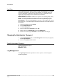
User Management....................................................................................................................... 57
Add a New User ................................................................................................................... 57
User Rank ............................................................................................................................ 58
Changing the Administrator Password ....................................................................................... 58
Default Administrator Password .......................................................................................... 58
Log Management ........................................................................................................................ 58
Set up Log Management Options ....................................................................................... 59
Status Check / Email ................................................................................................................... 60
General ................................................................................................................................ 60
Users .................................................................................................................................... 60
Storage Check ..................................................................................................................... 61
________________________________________________________________________________________________________
Document 800-03703V1 Rev B
13
10/11
Contents
Recording Data Check ........................................................................................................ 61
SMART Information .............................................................................................................. 61
SMART Alert ......................................................................................................................... 62
Alarm Event .......................................................................................................................... 62
Data Management....................................................................................................................... 62
Information ......................................................................................................................................... 63
Instant Recording ............................................................................................................................... 64
Activate Instant Recording .......................................................................................................... 64
Searching ‘Instant Recorded’ Video ........................................................................................... 64
7
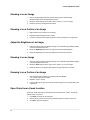
Search ........................................................................................................................................................ 65
Search Overview ................................................................................................................................ 65
Play Controls ............................................................................................................................... 66
Hour / Minute Controls ................................................................................................................ 66
Brightness / Speed / Zoom ......................................................................................................... 66
Adjusting the Brightness of an Image ........................................................................................ 66
Zooming in on an Image............................................................................................................. 67
Zooming in on a Portion of an Image ......................................................................................... 67
Adjust the Brightness of an Image ............................................................................................. 67
Zooming in on an Image............................................................................................................. 67
Zooming in on a Portion of an Image ......................................................................................... 67
Open Video from a Saved Location ........................................................................................... 67
Time Sync ................................................................................................................................... 68
After Image Removal................................................................................................................... 68
Performing a Basic Search ................................................................................................................ 68
Printing an Image ............................................................................................................................... 68
Daylight Saving Time ......................................................................................................................... 69
Save to JPG or AVI ............................................................................................................................. 69
Bookmarks .................................................................................................................................. 71
Modify Bookmarks ............................................................................................................... 71
Single Clip Backup .............................................................................................................. 72
Single Clip Backup Using Bookmark Data ......................................................................... 72
Index Search ...................................................................................................................................... 73
Performing an Index Search ....................................................................................................... 73
Index Search Results Display ..................................................................................................... 73
Preview Search ................................................................................................................................... 74
Performing a Preview Search ..................................................................................................... 75
Object Search ..................................................................................................................................... 75
Performing an Object Search ..................................................................................................... 76
Status Search ..................................................................................................................................... 77
Performing a Status Search ........................................................................................................ 77
Motion Search .................................................................................................................................... 78
Performing a Motion Search ....................................................................................................... 78
Audio Playback .................................................................................................................................. 79
8
Pan / Tilt / Zoom ......................................................................................................................................... 80
Pan / Tilt / Zoom Overview ................................................................................................................. 80
Enable the PTZ Settings ............................................................................................................. 80
Advanced PTZ Setup ......................................................................................................................... 81
________________________________________________________________________________________________________
14
Fusion IV NVR User Guide
Creating and Viewing Preset Positions ...................................................................................... 81
Creating a Preset ........................................................................................................................ 81
Viewing a Preset .................................................................................................................. 82
Understanding Tours .................................................................................................................. 82
Creating a Preset Tour......................................................................................................... 83
Viewing the Preset Tour....................................................................................................... 83
Creating a Preset Tour2....................................................................................................... 83
Viewing the Preset Tour2..................................................................................................... 83
Creating a Mimic Tour ......................................................................................................... 83
Viewing the Mimic Tour ....................................................................................................... 83
PTZ Status on Close ................................................................................................................... 84
Activating the PTZ Status on Close Option ......................................................................... 84
PTZ Tour Scheduling .................................................................................................................. 84
Create PTZ Tour Schedule .................................................................................................. 84
PTZ Address Setting .......................................................................................................................... 85
Accessing PTZ Menus ....................................................................................................................... 85
Opening and Editing the Honeywell MAXPRO Menu ................................................................ 85
Controlling a PTZ Camera.................................................................................................................. 86
Using the On-Screen Compass .................................................................................................. 86
Using the PTZ Controller ............................................................................................................ 87
AUX Buttons ......................................................................................................................... 87
9
Backing up Video Data .............................................................................................................................. 88
Backup Overview ............................................................................................................................... 88
Nero® Express ............................................................................................................................. 88
General Screen Overview ........................................................................................................... 89
Performing a General Backup ............................................................................................. 89
Clip Screen Overview .................................................................................................................. 90
Performing a Clip Backup ................................................................................................... 90
Scheduled Screen Overview ...................................................................................................... 91
Performing a Scheduled Backup ........................................................................................ 91
Specifying Scheduled Backup Drives ................................................................................. 91
10
LAN / ISDN / PSTN Connections ............................................................................................................... 92
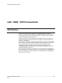
LAN Overview ..................................................................................................................................... 92
Connecting to a LAN Using TCP/IP ................................................................................................... 93
Configuring TCP/IP Settings ....................................................................................................... 93
11
LDAP Integration........................................................................................................................................ 94
Features .............................................................................................................................................. 94
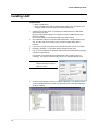
Installing LDAP ................................................................................................................................... 95
12
Web Viewer ................................................................................................................................................ 97
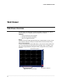
Web Viewer Overview......................................................................................................................... 97
Configuring the Server for Remote Connection ......................................................................... 98
Connecting to a DVR Using Web Viewer ................................................................................... 98
Closing the Web Viewer .............................................................................................................. 98
13
Included Software Setup ........................................................................................................................... 99
Proprietary Viewer Overview .............................................................................................................. 99
Installing the Proprietary Viewer ............................................................................................... 100
Loading Video from DVD-ROM or Hard Drive .......................................................................... 100
________________________________________________________________________________________________________
Document 800-03703V1 Rev B
15
10/11
Contents
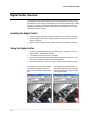
Digital Verifier Overview ................................................................................................................... 101
Installing the Digital Verifier ...................................................................................................... 101
Using the Digital Verifier............................................................................................................ 101
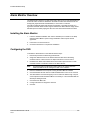
Alarm Monitor Overview ................................................................................................................... 102
Installing the Alarm Monitor ...................................................................................................... 102
Configuring the DVR ................................................................................................................. 102
Configuring the Client PC ......................................................................................................... 103
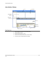
Alarm Monitor Window.............................................................................................................. 104
Filter Event List................................................................................................................... 104
Search Alarm Window .............................................................................................................. 105
View Recorded Video ........................................................................................................ 105
Export Video ...................................................................................................................... 105
Fusion Remote Software Overview .................................................................................................. 106
Remote Client Minimum Requirements .................................................................................... 107
Remote Client Recommended Requirements.......................................................................... 107
Installing the Fusion Remote Software ..................................................................................... 107
Setting up the Server to Accept Incoming Communications ................................................... 108
Setting up the Fusion Remote Software ................................................................................... 109
Creating a New Remote Connection................................................................................. 109
FVMS Overview ................................................................................................................................ 110
FVMS System Requirements .................................................................................................... 110
Configuring the Server for Remote Connection ....................................................................... 111
Connecting to a DVR ................................................................................................................ 111
Health Check............................................................................................................................. 112
Enable Health Check on the Fusion DVR ......................................................................... 112
________________________________________________________________________________________________________
16
Fusion IV NVR User Guide
Introduction
Product Description
The Honeywell Fusion NVR is a server that performs as a High Definition Digital
Recorder. By utilizing the many features of a computer, including processing power,
storage capacity, graphics compression, and security features, the NVR is more
powerful than the analog recorders of the past.
The Fusion series Network recorders are designed to capture video streams from
network cameras and video servers and then record to hard drives for storage
purposes.
The Honeywell Fusion NVR server software comes pre-configured for fast and seamless
integration within the existing IT infrastructure. Designed around Microsoft® Windows 7,
the server software offers unparalleled stability, security, and ease of use. Accordingly, a
security investment has never been easier to maintain. Multiple users may
simultaneously connect through any network connection for instantaneous live viewing,
digital search, and off site video storage. Users can also connect remotely through DSL,
Cable Modems, and ISDN. This powerful software enables users to establish recording
schedules, create motion detection zones, and use PTZ controls. With the latest
advancements in the NVR Server Software, searching and indexing the video archive
has never been easier. Video can be found, viewed, and exported in a number of file
formats with just a few clicks.
The Honeywell Fusion NVR is a high performance security product ready to meet
today’s security demands.
________________________________________________________________________________________________________
17
Introduction
Features
Honeywell’s Fusion NVRs include the following features:
•
•
•
•
•
•
•
•
•
•
•
•
•
•
•
•
•
•
Optimized and designed for Microsoft® Windows 7 Embedded®
Available 8, 16, and 32 channel configurations.
Support for most industry leading network camera manufacturers.
Remote system operation & configuration
Supports multiple simultaneous remote connections
Pan / Tilt / Zoom controls
Simultaneous video search, playback, and backup
Video indexes for easy searching
Multiple levels of security access
1 channel of audio per camera (only on IP cameras that support audio)
Supports resolutions up to 5 megapixel
High performance, durable, rack mount case
NTSC and PAL supported
Virtually unlimited storage potential
Supports digital signatures authentication
Continuous motion detection, alarm, pre-alarm, and scheduled recording modes
Software watchdog
Camera dependant recording resolution
________________________________________________________________________________________________________
Document 800-03703V1 Rev B
18
10/11
Fusion IV NVR User Guide
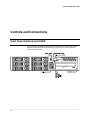
Controls and Connections
Front Panel Controls and LEDS
The front panel of the NVR contains the devices that will be commonly used for data
removal, retrieval, and backup replacement. The most common components and
buttons are shown below.
________________________________________________________________________________________________________
19
Controls and Connections
Rear Panel Connectors
The rear panel of the NVR contains virtually all of the necessary connectors. Below is a
diagram that outlines the location and description of each connector:
________________________________________________________________________________________________________
Document 800-03703V1 Rev B
20
10/11
Fusion IV NVR User Guide
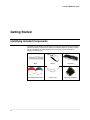
Getting Started
Identifying Included Components
Honeywell’s Fusion NVRs come with a mouse, keyboard, selected software and cables.
Identify the following components to make sure everything has been properly included
with the new NVR. If any of the following items are missing, contact the dealer to
arrange for a replacement.
NVR
Mouse
Keyboard
Power Cord
DVI-I to VGA adapter
6
DVR Repair/Software Disc
________________________________________________________________________________________________________
21
Getting Started
Keyboard Setup
To attach the keyboard to the recorder, plug the end of the Keyboard into a USB port
located on the back of the machine.
Mouse Setup
To attach the mouse to the recorder, plug the end of the mouse into a USB port located
on the back of the machine.
The mouse uses a cursor called a pointer. Pointers come in many different shapes but
are most commonly shaped like an arrow.
The mouse has two buttons: a left button and a right button. Quickly pressing and
releasing one of these buttons is called clicking. Sometimes you will need to doubleclick – or click the same button twice quickly.
In this manual:
Click means to position the mouse cursor over an item and to single click the left
button.
Right click means to position the mouse cursor over an item and to single click the
right button.
Double-click means to position the mouse cursor over an item and to click the left
button twice.
Select means to position the mouse cursor over a radio button, checkbox, or list item
and click on it.
The scroll wheel in between the two buttons is used for added navigation functionality.
By moving the wheel with index finger (scrolling), quickly move through multiple pages,
lines, or windows. The wheel may also function as a third button allowing the user to
quickly click or double-click an icon or a selected item
Scroll Button / Third Button
Right Button
Left Button
________________________________________________________________________________________________________
Document 800-03703V1 Rev B
22
10/11
Fusion IV NVR User Guide
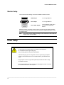
Monitor Setup
The recorder has the following connections available to attach a monitor.
HDMI Output
To TV / Digital Monitor
DVI -I Output
To TV / Digital Monitor
DVI to SVGA Adapter
Connect adapter to DVI output
to connect an analog VGA
Monitor.
Attach the monitor or monitors to the rear of the recorder using the cable supplied by
the monitor manufacturer. Refer to the monitor manual for detailed information on how
to setup and use it.
Note
The monitor must be capable of having a screen resolution of 1024 x 768 and
display colors of at least 32 Bit
Power Setup
WARNING:
To reduce the risk of electrical shock or damage to the equipment:
Do not disable the power grounding plug.
The grounding plug is an important safety feature.
If the electrical plug you are using does not have a ground plug receptacle
contact a licensed electrician to have it replaced with a grounded electrical
outlet.
Plug the power cord into a grounded (earthed) electrical outlet that is easily
accessible at all times.
Disconnect the power from the computer by unplugging the power cord either
from the electrical outlet or the computer.
________________________________________________________________________________________________________
23
Getting Started
Optional Components
To fully utilize the potential of the NVR, several optional Fusion components are listed
below. Contact a dealer for more information.
•
•
•
•
•
•
•
•
•
Internal RAID 5
External RAID 5 Storage
External SATA Storage
SCSI Interface card
Gigabit 10/100/1000 NIC Adapter
Performance package upgrade
Fusion Video Management Software
Fusion Remote Video Software
2U NVR Rackmount Rails
Turning On the Recorder
Once the cables and adapters have been properly connected it is time to turn on the
power. To turn on the power follow these steps:
1.
2.
3.
Turn on the monitor and any external peripherals (ex. Printers, External Storage
Devices, etc.) connected to the recorder.
Turn on the Secondary Power Switch located in the rear of the recorder.
Turn on the main power switch located on the front of the recorder.
The recorder will run a series of self-tests. After two or three minutes a series of
messages may be displayed as the various hardware and software subsystems are
activated. Under normal circumstances you should not be asked to respond to these
messages. If you are asked to respond to the messages (adding a Printer, Monitor, etc
for the first time) follow the instructions carefully.
After this finishes, the Fusion recorder software should load automatically and bring you
to the main screen.
Turning Off the Recorder
To turn off the recorder, select the Exit button on the main screen and select Power Off.
The recorder will safely shutdown, it may take several minutes to shut down completely.
Caution
Always be sure to follow the proper procedures when turning off the power
to the recorder. NEVER disconnect the power to the recorder while it is still
running or in the process of shutting down. Doing so can cause data loss,
file corruption, system instability and hardware failure
________________________________________________________________________________________________________
Document 800-03703V1 Rev B
24
10/11
Fusion IV NVR User Guide
DVR Basics
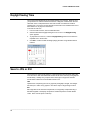
Setting the Time and Date
1.
Exit to Windows by clicking Exit on the Live View screen and selecting Restart in
Windows Mode. (See the Live View screen section later in this chapter)
2.
Open Windows Explorer. Do this by right-clicking the My Computer icon (located
on the top left hand corner of the Desktop) and select Explore.
3.
Click on Control Panel to open it. If you do not see Control Panel listed, Click My
Computer to expand the folder tree.
4.
Double-click Date and Time inside Control Panel.
5.
Adjust the Date and Time.
6.
When finished, close all open windows and restart the recorder.
________________________________________________________________________________________________________
25
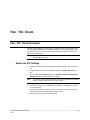
DVR Basics
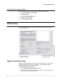
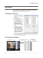
Accessing the DVR Utility
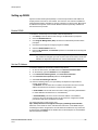
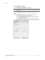
Exporting DVR Settings
Exporting DVR settings can help configure multiple DVRs quickly or reconfigure a unit
that has failed. Some things must be kept in mind when using this feature.
You cannot use this function on:
• DVRs that are different models.
• When upgrading from certain software versions. (This feature cannot be used
when upgrading from v2.x to v3.x)
1.
Exit to Windows by clicking Exit on the Live View screen then and select Restart in
Windows Mode. (See the Live View screen section later in this chapter)
2.
Open the DVR Utility window by clicking the Start button
Programs, clicking Fusion, and then clicking vFormat.
3.
Click Export in the System Setting tool section.
4.
Select a location to save the settings file and click Save. The DVR Utility will export
the DVR settings and automatically close.
, clicking All
Importing DVR Settings
1.
Exit to Windows by clicking Exit on the Live View screen then and select Restart in
Windows Mode. (See the Live View screen section later in this chapter)
2.
Open the DVR Utility window by clicking the Start button
Programs, clicking Fusion, and then clicking vFormat.
3.
Click Import in the System Setting Tool section.
4.
Select the location of the settings file to import and click Open.
5.
Click Yes to import the data file.
, clicking All
________________________________________________________________________________________________________
Document 800-03703V1 Rev B
26
10/11
Fusion IV NVR User Guide
Changing Video Format
1.
Exit to Windows by clicking Exit on the Live View screen then and select Restart in
Windows Mode. (See the Live View screen section later in this chapter)
2.
Open the DVR Utility window by clicking the Start button
Programs, clicking Fusion, and then clicking vFormat.
3.
Select the appropriate video setting from the list in the Video Setting section –
NTSC or PAL..
4.
Click Set.
, clicking All
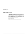
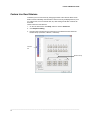
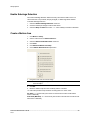
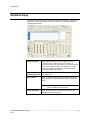
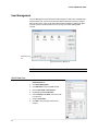
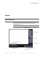
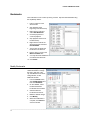
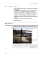
Live View screen
Each time the recorder starts, the program defaults to the Live View screen. The
following diagram outlines the buttons and features used on the Live View screen. You
should become familiar with these options as this is the screen that will be displayed the
majority of the time.
Current Date & Time
Menu Buttons
Displays
Connected Users
Status of/Activates
Control Outputs
Camera Display Buttons
Status of/Activates
Alarm Sensors
________________________________________________________________________________________________________
27
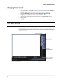
DVR Basics
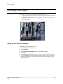
Live Camera Options
Right-click a camera on the Live View
screen to display these options:
•
•
•
•
Full Screen
Instant Recording
Search In Live
Digital Zoom
________________________________________________________________________________________________________
Document 800-03703V1 Rev B
28
10/11
Fusion IV NVR User Guide
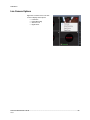
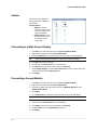
Camera View
Special Recording Status
Current Recording Status
Camera No. and Name
Recording Status Indicator
The camera status for each camera is displayed in the upper right corner on the Video
Display Area. The following are the different states for each camera:
Recording
Displayed when the camera is currently being recorded to
the recorder.
Motion Detection
Displayed when a camera (set up for motion detection)
detects motion.
Display
Displayed when the camera is currently not being
recorded to the recorder.
Special Recording
There are two types of Special Recording. Text is displayed on the camera indicating
what type of Special Recording is activated.
SENSOR
Sensor is displayed when a sensor, associated with a given camera, is
activated.
INSTANT
Instant Recording is a manual activation of the recording for the selected
camera. Regardless of the recording method, Instant Recording will start
the camera recording and also flag the video for future searches using
the Index Search feature. INSTANT is displayed when a user activates the
instant recording option. Double Right-Click the video display to activate
and deactivate the Instant Recording option.
________________________________________________________________________________________________________
29
DVR Basics
Screen Division Buttons
Note
When viewing live video from Network Cameras, only 4CH will display at one
time.
Quad View
Displays cameras 1-4, 5-8, 9-12, 13-16, etc. in the
Video Display Area.
Nine Camera View
Displays cameras 1-9, 10-18, etc. in the Video
Display Area.
16 Camera View
Displays the first 16 cameras in the Video Display
Area.
Full Screen
Displays the current camera display configuration
full screen.
Auto-Sequence
Sequences through the Screen Divisions sets of
4, 9, or 16 cameras.
Dual Monitor Camera Display Menu
When dual monitors are enabled, you can adjust the camera display for live view on the
secondary display. Move the mouse to the top of the screen and the camera display
menu will appear.
________________________________________________________________________________________________________
Document 800-03703V1 Rev B
30
10/11
Fusion IV NVR User Guide
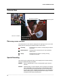
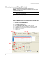
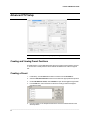
Custom Live View Divisions
Customize your Live View screen by changing the order of the cameras. Each screen
division can be individually customized but a camera can only be displayed once (once
in 4 camera view, once in 9 camera view, etc). Both analog and IP video cameras can
be moved.
Create custom live view divisions:
1.
On the Live View screen click Setup, and then click the General tab.
2.
Click Sequence Setting.
3.
Drag and drop cameras from the Channel List to the desired location within the
Division Group (4 Division, 9 Division, 16 Division).
Channel
List
Division Group
________________________________________________________________________________________________________
31
Setup Options
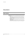
Setup Options
Setup Overview
The Setup options allow optimization of the DVR by adjusting things like camera names,
recording schedules and more. It is extremely important to setup the DVR correctly for
several reasons:
• Recording Schedules –Increase the amount of pertinent recorded video that is
saved on the DVR by optimizing the recording schedule. Optimize the type of
recording done by adding motion detection to this as well, again increasing the
amount of useful video.
• DVR Access – By setting up the access passwords, the user has better control
of the types of access any individual may have. This ensures the security and
integrity of the DVR.
• Camera Naming – By naming each camera, the location and any other pertinent
information can be easily identified when viewing it in the Video Display Area.
________________________________________________________________________________________________________
Document 800-03703V1 Rev B
32
10/11
Fusion IV NVR User Guide
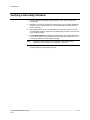
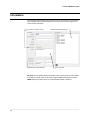
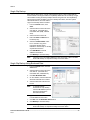
Setup Screen
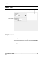
Camera Setup
Assign names to each camera.
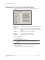
Network Video
Register and add network video devices, and adjust basic settings.
Motion
Create up to 15 video detection areas,
General
Configure display options, alerts, intensive recording
Recording Schedule
Create custom recording schedules for each channel, sensor, and special days.
Network
Assign network settings.
Administration
Set permissions for users, export logs, adjust HDD storage
Information
View version numbers, save contact numbers, and view available HDD status.
PTZ
Set up preset positions, tour and assign protocols.
________________________________________________________________________________________________________
33
Setup Options
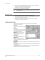
Camera Setup
Displays live video from a
selected camera
Define camera name
Set Up New Camera
1.
Attach camera to the rear of the DVR chassis.
2.
Click Setup on the Live View screen.
3.
Click Camera Setup to open the Camera Setup display.
4.
Select the channel that corresponds with the new camera from the Select Camera
list.
5.
Enter a name for the camera in the Camera Name box.
6.
Click Apply when finished.
________________________________________________________________________________________________________
Document 800-03703V1 Rev B
34
10/11
Fusion IV NVR User Guide
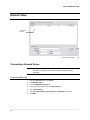
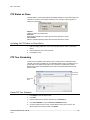
Network Video
Connected
Devices
Automatic Camera Finder
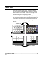
Connecting a Network Device
Note
Refer to the EQUIP Series Network IP camera user guide for detailed
information on setting up that camera using the Honeywell IP Utility
application.
Connecting Manually
1.
From the Live View screen, click Setup.
2.
Click Network Video.
3.
Click the Add/Remove Device tab.
4.
Select your network device from the Device Type list.
5.
Type a Device Name.
6.
Type the IP/URL address, Port#, User ID and Password of the device.
7.
Click Add.
________________________________________________________________________________________________________
35
Setup Options
Connecting with Camera Finder
1.
From the Live View screen, click Setup.
2.
Click the Network Video tab.
3.
Click the Add/Remove Device tab.
4.
Click Find Cameras to automatically find all connected Network cameras.
5.
Select the check box next to the desired camera.
6.
Click Get Device.
7.
Type the User ID and Password of the device.
8.
Click Update.
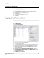
Assigning a Network Device to a Channel
Note
Fusion IV recorders support single stream IP camera operation. Dual stream
operation is not supported.
1.
From the Live View screen, click Setup.
2.
Click Network Video.
3.
Click the Channel Setup tab.
4.
Click an available channel on the Channel List.
5.
Type the desired Position Name.
6.
On the Select Device list, select the appropriate network device added previously.
7.
If the device has PTZ capabilities, select the PTZ Camera check box to enable.
8.
If the device displays wide screen video, select the Wide Screen check box to
allow it to display properly.
9.
If supported, select the Use Network Camera Motion Detection check box.
10. Select Intensive Motion, Intensive Sensor, and/or Intensive Instant to increase
the recording rate on an event.
11. Click Apply to save your selections.
________________________________________________________________________________________________________
Document 800-03703V1 Rev B
36
10/11
Fusion IV NVR User Guide
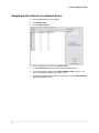
Assigning Audio Channels to a Network Device
1.
From the Live View screen, click Setup.
2.
Click Network Video.
3.
Click the Audio Setup tab.
4.
Click an available audio channel on the Channel List.
5.
On the Select Device list, select a network device added previously.
6.
To record the network audio select the Record Network Audio check box. The
audio channel will be available on the search screen.
7.
To access the audio channel from the Live View screen, select the Enable Network
Video in Live View check box.
________________________________________________________________________________________________________
37
Setup Options
Camera Configuration
The Camera Configuration tab displays information on all cameras (analog and
network) connected to the Fusion recorder
Enable/Disable Live Video
• To enable a network device to display as live video select the check box next to
the Camera Name that you want available for live video display.
• To disable live video for a network device, clear the check box next to the
Camera Name.
Displaying More Columns
The Camera Configuration tab can be customized to display the information you use
most. Click Select Column to add or remove specific columns.
Capture FPS
IP Address
Codec
Record FPS
Port Number
Quality
Schedule
Resolution
PTZ
Manufacturer
Record FPS
Model
Frame Rate
________________________________________________________________________________________________________
Document 800-03703V1 Rev B
38
10/11
Fusion IV NVR User Guide
Accessing the Configuration Menu
Use the Fusion interface to access basic network device menu functions.
1.
From the Live View screen, click Setup.
2.
Click Network Video.
3.
Click the Camera Configuration tab.
4.
Highlight the desired camera.
5.
Click Setup Network Device.
Motion Setup
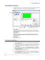
The recorder allows the user to adjust several different Motion Settings and create
motion detection areas.
Apply Current Motion
Areas to all Channels
Reduces Analog Signal Noise
from Motion Detection
Regular Interval Recording
Regular Interval Recording allows users to record a single frame every few minutes or
hours even when there is no motion. This option is only available when Motion
recording is selected in the recording schedule.
To enable Regular Interval Recording:
1.
Select the Regular Interval Recording check box.
2.
Specify how often to take an image when no motion is occurring. System can be
set to as many as one image per second.
________________________________________________________________________________________________________
39
Setup Options
Enable Sabotage Detection
The Camera Sabotage Detection feature will notify users that the field of vision of a
camera has been compromised, abruptly changed, or detects significant vibration.
To enable Sabotage Detection:
1.
Select the Enable Sabotage Detection check box.
2.
Set the threshold percentage to reduce false alarms.
3.
Select the Beep on Detect check box – or – select a Relay to activate on detection.
Create a Motion Area
1.
Click Motion in Setup.
2.
Select a camera from the Select Camera list.
3.
Select the Detect Detail Motion Area check box.
4.
Click Clear.
5.
Click Advanced Motion Area Setup.
6.
Click a Motion Detection Area shape button.
7.
Drag the mouse over the camera image.
Note
To create a polygon shape, click the mouse at each point and double-click to
close the shape.
8.
Click OK.
9.
Move the sliders to adjust motion sensitivity and the noise filter.
10. Define the pre-alarm and post-alarm recording time for a motion event.
Pre Alarm – 0 > 50 Seconds [The number of seconds the recorder records before
motion is detected]
Post Alarm (MOTION) – 0 > 50 Seconds [The number of seconds the recorder records
after motion is detected]
________________________________________________________________________________________________________
Document 800-03703V1 Rev B
40
10/11
Fusion IV NVR User Guide
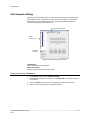
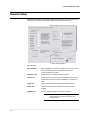
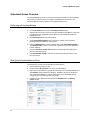
General Setup
Adjust/Mute volume
Function
Beep on Login Fail
Enables the DVR to beep continuously in response to a failed
login attempt. Only an authorized login will stop the beeping.
Sequence Setting
Allows the video out picture to automatically cycle through
channels at a set speed. Example: .Cycle through channels 16 at four-second intervals.
Display Options
Use Full Screen
Stretch the Fusion software to use the full monitor screen.
Display Size
Select from available monitor display sizes. Use to correctly
display video on wide screen monitors.
Motion Detect on
Continuous
recording
Allows you to process and receive motion events and alarms
while recording in continuous mode. Also enhances search
capabilities when recording in continuous
Note
Motion Detect on Continuous is not supported on IP
cameras.
________________________________________________________________________________________________________
41
Setup Options
Voice Warning
The recorder allows users to play a sound file when either a Motion event or Sensor
event occurs. This file can be a custom created sound file that is unique to the
application. The selected WAV file is played through speakers attached to the recorder.
Test Sound File
Locate Sound File
1.
Click the Open Sound File icon to browse for a WAV file. The selected file will
display in the box on the left.
2.
Click the Test icon to verify the audio file.
3.
Select Activate on Motion, Activate on Sensor (Alarm), and or Activate on
Sabotage Detection to trigger the audio file.
Video Loss Alarm
The DVR supports a Video Loss Alarm function which allows an Alarm Event to occur
when a camera loses its signal. The lost signal can be due to camera power failure to
the camera, the camera cable being cut or unplugged, or the camera being damaged in
some way.
In order to use Video Signal Loss detection, cameras must either be Enabled or
Disabled. This is because the DVR needs to know which cameras it should expect to
receive signals from. To enable camera(s), open Frame Setup, and set the Images Per
Second to anything above zero. By designating zero images per second the camera will
not be used by the DVR.
Activate Audio Alarm (BEEP)
When video loss occurs, an internal speaker on the DVR will sound an alarm.
Video Loss Alarm Log
When video loss occurs, the event is recorded in the DVR log.
________________________________________________________________________________________________________
Document 800-03703V1 Rev B
42
10/11
Fusion IV NVR User Guide
Volume
The volume control allows fine
tuning of the volume settings on
the recorder.
Volume Options:
• Speakers – Used to
adjust the volume for all
sound coming from the
system’s speakers
• System Sounds – Used
to adjust the volume for
the system sounds
exclusively.
Connecting to a Wide Screen Display
1.
Click Exit on the Live View screen and select Exit in Windows Mode.
2.
Right-click the Desktop and select Screen Resolution.
3.
From the Resolution list, select the proper resolution of the connected display.
Tip
Refer to the display documentation for the proper resolution settings.
4.
Click OK and confirm the change.
5.
Double-click the Fusion Server icon on the Desktop.
6.
Click Setup on the Live View screen and then click General.
7.
Under Display Settings, select the Use Full Screen check box and then select the
correct resolution from the Display Size list.
8.
Click Apply.
Connecting a Second Monitor
1.
Click Exit on the Live View screen and select Exit in Windows Mode.
2.
Right-click the Desktop and select Screen Resolution.
3.
Click the secondary Live View screen and from the Multiple displays list click
Extend these displays.
4.
Click Apply.
5.
On the Resolution list, select the proper resolution of the connected display.
Tip
Refer to the display documentation for the proper resolution settings.
6.
Click OK and confirm the change.
7.
Double-click the Fusion Server icon on the Desktop.
8.
Click Setup on the Live View screen and then click General.
9.
Under Function, select the Dual Monitor check box.
10. Click Apply.
________________________________________________________________________________________________________
43
Setup Options
Auto Sequence Setting
Auto Sequencing is available either in the Live View screen when Auto Sequencing has
been enabled or when a Spot-Monitor out signal is used to display on a spot monitor.
Auto Sequencing conveniently displays video channels at specified intervals and
sequences through each selected channel.
Screen Division Options
Enable
Sequencing
Enable All
Cameras
Select interval between switching cameras
Custom Mode
Create non-standard screen divisions
Skip 0 FPS Channel
Sequence skips cameras with no video signal
Create Custom Auto Sequence
1.
Open General setup and click Sequence Setting.
2.
Click individual cameras in the left pane or click Select All to include all cameras in
the sequence.
3.
Select an Interval time (in seconds) to display each screen in the sequence.
4.
Select screen division options for appropriate cameras.
________________________________________________________________________________________________________
Document 800-03703V1 Rev B
44
10/11
Fusion IV NVR User Guide
Hybrid Sensor Setup
This interface is used to link Hard Contact Sensor Inputs from supported Network
Devices to the recorder software.
________________________________________________________________________________________________________
45
Setup Options
Schedule Setup
Creating a customized schedule is important to maximize the efficiency of the recorder.
The Fusion recorder offers numerous options to allow for a wide variety of different
needs and requirements.
Schedule Number
The Schedule Number is a group of settings. Up to 32
schedules can be created. Think of the schedules as
transparency paper with words written on them. When placed
one on top of another, the words can still be seen from the
layers below. These schedules allow a powerful detailed
recording schedule to be created.
Special Day
Recording Schedule
Customize a schedule for a particular day, such as a Parade
Day, Holiday, etc.
Alarm Options
These are advanced options that send alarm events (either
motion or sensor) to the remote alarm monitor software and
FVMS.
Tip
Power Off Options
To send motion events to FVMS, select both Motion
Event and Map Alarm check boxes.
Allows the user to specify time frames for turning off and
restarting the DVR automatically.
________________________________________________________________________________________________________
Document 800-03703V1 Rev B
46
10/11
Fusion IV NVR User Guide
Default Schedules
Default Schedule 1
All cameras are set to: 8AM-5PM. Continuous recording 5PM-8AM Motion recording
Default Schedule 2
All cameras are set to: Motion recording 24 hours/day, 7 days/week.
Camera 1 associated to sensor input 1
Camera 2 associated to sensor input 2
Camera 3 associated to sensor input 3, etc.
Note
Default Schedule 1and Default Schedule 2 are not configured for use with
sensors/alarms.
Day of the Week
The Day of Week is the day of the week for which the schedule is being edited. If WED
is checked, Wednesday’s schedule is being edited.
The Single Selection Mode button allows selection of multiple days at once.
By selecting the Single Selection Mode button placing multiple checks in the boxes is
allowed, thereby selecting multiple days simultaneously.
Clicking on Single Selection Mode will change the button to Multi Selection Mode. This
allows you to select multiple days to configure at once.
Creating a Simple Schedule (By Example)
Creating schedules is easy with a little experience. In the following example, the steps
for creating a simple schedule for cameras 1 to 4 are detailed.
The schedule will be as follows:
• MON-FRI (9AM-5:59PM) all 4 cameras will record using MOTION recording.
• MON-FRI (6PM-8:95AM) all 4 cameras will record using CONTINUOUS
recording.
• SAT-SUN (12AM-11:59PM) all 4 cameras will record using MOTION recording.
Using these examples, a total of 3 schedules will be created.
________________________________________________________________________________________________________
47
Setup Options
Steps 1-6:
Schedule cameras 1-4 to record on MOTION from 9:00am-5:59pm
Monday through Friday.
1.
Select Sch01 from the Schedule Number list. (This should already be selected by
default)
2.
Click the Single Selection Mode button.
3.
Select the MON, TUE, WED, THU, and FRI days of the week check boxes.
4.
On the Sch01 line on time selector grid, highlight hours 09-17. Click Set.
5.
Click Camera buttons 1-4 until the green Motion buttons are selected.
6.
Click Apply to save.
Step 3
Step 2
Step 4
Step 1
Step 5
________________________________________________________________________________________________________
Document 800-03703V1 Rev B
48
10/11
Fusion IV NVR User Guide
Steps 7-11:
Schedule cameras 1-4 to record on CONTINUOUS from 6:00pm8:59am Monday through Friday.
1.
Select Sch02 from the Schedule Number list.
2.
On the Sch02 line again, highlight the hours 18-23 (for 6:00pm-midnight) and click
Set.
3.
On the Sch02 line on time selector grid, highlight the hours 00-08 (for midnight to
8:59am) and click Set.
4.
Click Camera buttons 1-4 until the maroon Continuous buttons are selected.
5.
Click Apply to save.
Step 9
Step 8
Step 7
Step 10
________________________________________________________________________________________________________
49
Setup Options
Steps 12-17: Schedule cameras 1-4 to record on MOTION from
12:00am-11:59pm Saturday and Sunday
1.
Select Sch03 from the Schedule Number list.
2.
Select the SAT and SUN check boxes.
3.
Clear all other Day of Week check boxes
4.
On the Sch03 line on the time selector grid, highlight hours 00-23
and click the Set button.
5.
Click Camera buttons 1-4 until the Green Motion buttons are selected.
6.
Click Apply to save.
Step 13 & 14
Step 15
Step 12
Step 16
________________________________________________________________________________________________________
Document 800-03703V1 Rev B
50
10/11
Fusion IV NVR User Guide
Scheduling Sensors and Relays (By Example)
It is easy to add advanced recording functionality using Sensor Inputs.
SENSOR - Sensor Inputs can be programmed to instantly start one or more cameras
recording when an alarm occurs.
Note
You must first associate the software sensors with the sensors (click Hybrid
Sensor Setup on the General tab).
The schedule example will be as follows:
• SUN-SAT (12AM-11:59PM) Cameras 1 and 2 will be activated on Sensor #3
and/or Sensor #5.
Steps 1-7: Schedule cameras 1 and 2 to be activated on Sensor # 3 and/or
Sensor #5.
1.
Select Sch01 from the Schedule Number list.
(This should already be selected by default.)
2.
Click the Single Day Selection button.
3.
Select the SUN, MON, TUE, WED, THU, FRI, and SAT check boxes.
4.
On the Sch01 line (time selector grid), highlight the hours 00-23 and click Set.
5.
Click Camera buttons #1 and #2 until the Red Sensor buttons are selected.
6.
Click Sensor buttons #3 and #5.
7.
Click Apply to save.
Step 2
Step 3
Step 4
Step 1
Step 5
Step 6
________________________________________________________________________________________________________
51
Setup Options
Verifying a Recording Schedule
1.
Select a single day of the week using the selection check box to the left of the
specified day.
2.
Identify the schedule (or schedules) that have specific hours of the day highlighted
in light blue color. The horizontal axis of the schedule grid corresponds to the 24
hours of each day.
3.
After verifying that all hours of the selected day are covered by at least one of the
32 independent schedules (vertical axis of schedule grid) now look to the lower half
of the schedule interface.
4.
In the Schedule Number list, select the schedule(s) that were defined above for the
current day and verify, in each schedule number, that the correct cameras are set
to Continuous, Motion or Sensor based recording.
Note
5.
If a specific camera should not be recorded on a given day/schedule
combination, set the camera to “Not Selected” - a white “X”.
Repeat this process for each of the 7 days of the week until certain that the desired
recording method is configured for each day.
________________________________________________________________________________________________________
Document 800-03703V1 Rev B
52
10/11
Fusion IV NVR User Guide
Network Setup
Network Setup allows the user to adjust settings such as Ports, setup emergency PPP
information for use with the Emergency Agent and enable Remote Access.
Enable 1-way audio from remote client to DVR
Enable RS-232 Keyboard
Network Setup
Time Out Value
When attempting to connect to the DVR, if the connection does
not succeed during the timeout period (seconds), the
connection will be terminated.
Emergency Port
Used to connect to the Alarm Monitor software.
Center Port
Used to connect to the Fusion remote software. This port must
be specified in the Fusion Remote Software to connect to the
DVR.
Image Port
Used to transfer the video to the Fusion remote software.
Search Port
Used to transfer search information to the Fusion remote
software.
Upgrade Port
Used to upgrade software via a remote connection.
Note
If connecting to the DVR through a firewall, the
above ports must be open to incoming and
outgoing traffic.
________________________________________________________________________________________________________
53
Setup Options
Web Function
HTTP Port
Used to transfer the DVR Interface via the Internet to the Web
Viewer. Default 80.
Internet Port
Used for Data communication between the DVR and the Web
Viewer. Default 4006.
Live Port
Used to transfer video via the Internet when Web Viewer is
enabled. Default 4007.
Health Check Port
Enables FVMS to receive information regarding the health of
the DVR.
Resolution
By setting the resolution low, the images will be sent faster,
however, the image quality will be reduced considerably. When
set to Original, full quality video will be sent [720 x 480 (NTSC)
720 x 576 (PAL)]. The Original setting is very bandwidth
intensive.
Transport Setup
Transport Rate
Throttles the bandwidth on the DVR. This option is based on
percentages of images sent. These settings affect the quality
and speed of the video that is sent to the remote clients.
Advanced
Configure the Transmit size on a per channel basis.
Administration
Select Date
Log Data
Export Log Data (1 to 7 days)
________________________________________________________________________________________________________
Document 800-03703V1 Rev B
54
10/11
Fusion IV NVR User Guide
Disk Management
The Disk Management window is a native Windows function. This window displays the
partition scheme and health status of the Hard Disk Drives in the recorder. This window
is often used to troubleshoot a recorder, or verify the amount of Hard Drive storage
installed. For more information about Disk Management, consult a Windows 7 manual.
________________________________________________________________________________________________________
55
Setup Options
Setting up DDNS
Dynamic Domain Name System (DDNS) is a service that provides a static address to
simplify remote connection to the recorder. This service is most useful for installations
where the WAN (public) IP address is dynamic (changes from time to time). Most public
IP addresses are dynamic unless a static address has been specifically ordered from
the internet service provider.
Enable DDNS
To enable this functionality of the recorder, follow the steps below:
1.
Click Setup on the Live View screen and log in as Administrator if prompted.
2.
Click The Administration tab.
3.
Click Program Management (ETC) and enter the Administrator password when
prompted.
4.
Click Show (to the right of The agent program for DDNS).
5.
Select the Enable DDNS check box.
6.
Enter the ID, Password, and Hostname specified on the DDNS document shipped
with your DVR.
Note
Ensure the DVR has an IP address by setting it statically. The Network settings
may need to be changed. If you are not sure of the correct values, contact the
individual or department responsible for network administration at the site.
Set the IP Address
To set the IP address of the recorder, follow the steps below:
7.
On the Live View screen, click Exit and choose Restart in Windows Mode.
8.
On the desktop, right-click Network and click Properties.
9.
In the Network and Sharing Center, click Local Area Connection.
10. Click Internet Protocol (TCP/IP) and then click Properties.
11. Select Use the following IP address.
12. Enter the following values (or as specified by the department responsible for
network administration).
a. IP Address: The first three sets of numbers should match the router’s local IP
address and the last set should be a unique number between 1-254.
b. Subnet Mask: This should match the router’s setting (commonly 255.255.255.0
for 192.X addresses and 255.0.0.0 for 10.X addresses).
c. Default Gateway: This is the router’s internal IP address. Once DDNS is
configured, the router the DVR connects to will need to be configured to forward
ports 80 and 4000 to the IP address of the DVR.
For further instruction on this process, visit
http://www.portforward.com/english/routers/port_forwarding/routerindex.htm
Select the correct model of router, and follow the instructions. Once DDNS and port
forwarding have been configured, the recorder will be accessible from any remote site
by entering the HOSTNAME into the address bar of Internet Explorer or the IP Address
field in the Remote Software.
________________________________________________________________________________________________________
Document 800-03703V1 Rev B
56
10/11
Fusion IV NVR User Guide
User Management
The User Management Console allows the administrator to create, edit, and delete user
accounts. Each user account can be assigned different privileges to limit the usage of
the recorder system. Users can be given administrator privileges by enabling all rights,
however only the true administrator account can log into the User Management
Console.
Enable Auto Log
Off
Log Off User after x Minute(s) of
Note
The Delete User button immediately deletes the user – use cautiously.
Add a New User
1.
From the Live View screen, click the
Administration tab.
2.
Click User Management.
3.
Click Add User to open the User window.
4.
Enter a User Name and Password.
5.
Enable appropriate Permissions.
6.
Select Cameras and Audio channels to hide
from the user.
7.
Assign a User Rank.
8.
Click OK to save changes and close the
window.
________________________________________________________________________________________________________
57
Setup Options
User Rank
The User Ranking structure allows the option to assign a privilege system (1-10 where
one has the most rights) to users of the recorder Software. For example. Since only
one user is allowed to use the PTZ controls at any one time, an administrator with a
higher rank can kick another user out and take control of the PTZ.
The User Rank option affects:
SETUP ACCESS - The recorder Software can only have 1 user accessing Setup at any
given time. A user with a higher rank will kick another user out and then open Setup.
NOTE: User settings will NOT be saved when a user with a higher ranking logs in.
PTZ CONTROL - The recorder SOFTWARE can only have 1 user using the PTZ controls
at any given time. A user with a higher rank will kick another user out and then open the
PTZ controls.
1.
From the Live View screen, click Setup.
2.
Click the Administration tab.
3.
Click User Management.
4.
Enter the Administrator password and click OK.
5.
Select a user from the Select User box and click Update User.
6.
Set the user’s rank using the User Rank list and click OK to save changes.
Changing the Administrator Password
1.
Inside the Administration tab, click User Management. When the prompt appears,
click Change Password.
2.
Enter the new password and click OK.
Default Administrator Password
The default administrator login is:
User: Administrator
Password: <blank>
Log Management
The Log Management window provides the user the options to overwrite log files or
schedule log deletion.
________________________________________________________________________________________________________
Document 800-03703V1 Rev B
58
10/11
Fusion IV NVR User Guide
Set up Log Management Options
1.
From the Administration tab, click Log Management.
2.
Select the check box to enable the Log File Overwrite Option.
Set Log Overwrite
a)
Select Overwrite and define the size of the log file cache.
Set Log Cache Size
a) Select Do Not Overwrite and define the number of days to maintain log files.
Manually Delete Log Files
a) Select the type(s) of log file to delete. System Log, Event Log, Alarm Log.
b)
3.
Click Delete All.
Click OK to save the settings and close the window.
________________________________________________________________________________________________________
59
Setup Options
Status Check / Email
General
1.
Click Setup on the Live View
screen.
2.
Click the Administration tab.
3.
Click Status Check/Email.
4.
Select the Enable Email Alarm
check box.
5.
Enter a From Name and e-mail
Address.
Note
This name and address will
appear in the From line of
the email alert message.
6.
Enter the SMTP information for
the “From” email account.
Contact the email administrator
for this information if necessary.
7.
If using a secondary e-mail account select the Use Secondary SMTP check box
and complete the SMTP information.
8.
Click Test to check settings.
9.
Click Apply when finished.
1.
Set up the General tab first.
Users
2.
Click the Users tab.
3.
Select the type of Event to send
email on.
4.
Enter the User Name and Email Address of an email
recipient.
5.
Click Add.
6.
Repeat for additional recipients
and types of events.
Note
7.
A separate email
notification for each type of
event must be set up for a
single recipient to receive
notifications for each type
of event.
Click Apply when finished.
________________________________________________________________________________________________________
Document 800-03703V1 Rev B
60
10/11
Fusion IV NVR User Guide
Storage Check
1.
Set up the General and Users
tabs first. (see previous sections)
2.
Select the Use Storage Check
check box.
3.
Define the number of minutes.
4.
Select an Alert Option, Beep or
Popup Message, if desired.
5.
Click Apply.
Recording Data Check
1.
Set up the General and Users
tabs first. (see previous sections)
2.
Select the Recording Data
Check check box.
3.
Define the number of hours
between data checks.
4.
Select the Action Method.
5.
Click Apply.
SMART Information
The SMART Information tab displays
Hard Drive information.
________________________________________________________________________________________________________
61
Setup Options
SMART Alert
1.
Set up the General and Users
tabs first. (see previous sections)
2.
Select the Enable SMART
Alarm check box.
3.
Define the number hours
between SMART checks.
4.
Select the type of SMART event
to trigger an action.
5.
Define the maximum HDD
temperature.
6.
Select an action method.
7.
Click Apply.
1.
Set up the General and Users
tabs first. (see previous sections)
2.
Select the Use Email Alarm
check box.
3.
Define the number of minutes
between recording data checks.
4.
Select Motion and/or Sensor to
send and alert on that type of
event.
5.
Click Apply.
6.
Click Close to return to the
Administration tab.
Alarm Event
Data Management
Data Management is available for select regions where operators must delete data after
a set number of days. If you need to purge your video data, and this feature is not
enabled on your Fusion recorder, contact Technical Support.
________________________________________________________________________________________________________
Document 800-03703V1 Rev B
62
10/11
Fusion IV NVR User Guide
Information
The Information display allows users to define the site code necessary for connecting to
remote software, save comments relative to the recorder and store tech support and
contact number information.
Current Server Software Version
User-Defined Contact Numbers
Total HDD /Available HDD Space
Enter comments
Site Code: A user-specified unique identification name used by other recorder software
to identify the recorder. (Remote, Emergency Agent, FVMS, Digital Signature Verifier)
CBSN: Displays the serial number of an internal DVR hardware component.
________________________________________________________________________________________________________
63
Setup Options
Instant Recording
The Instant Recording feature allows users to manually initiate recording on a specific
camera, overriding the current schedule. When Instant Recording is activated the
recorder flags the clip as an event so Instant Recording instances can be found using
the Index Search
Instant Recording can be used, for example, when a suspicious object or person is
detected and the user wants to flag that section of video for easy retrieval at a later date.
Activate Instant Recording
1.
From the Live View screen, double right-click the camera on which to enable instant
recording. An INSTANT label will be placed on the upper right corner of the video.
2.
To turn the Instant Recording option off, double right-click the camera a second
time.
Searching ‘Instant Recorded’ Video
1.
From the Live View screen click Search.
2.
Click Index Search.
3.
Select the Instant Recording option. See the Search chapter for more information.
________________________________________________________________________________________________________
Document 800-03703V1 Rev B
64
10/11
Fusion IV NVR User Guide
Search
Search Overview
The recorder has several options that allow the user to easily search through, and find,
a particular section of video. From Motion/Sensor indexing to calendar views
highlighting days with recorded video; the recorder is equipped to help the user quickly
find a specific video or event.
Note
16 Channel model shown below.
Actual Date/Time
Search Options
Play Controls
Screen Division Buttons
Search Date/Time
Select Cameras
Hour Minute Control
Calendar Button
________________________________________________________________________________________________________
65
Search
Play Controls
Rewind
Play
Back Frame
Forward Frame
Stop
Back Frame
Moves video back one frame.
Rewind
Rewinds video.
Play
Plays video.
Forward Frame
Moves video forward one frame.
Stop
Stops video playback
Hour / Minute Controls
The Hour/Minute Control Bar allows a user to select the Hour and Minute using an easyto-use slide bar. The user can control the slide bar by clicking and dragging the slider or
using the scroll wheel on the mouse.
Brightness / Speed / Zoom
The Brightness and Zoom features can get the most out of the images. Adjusting
Brightness can brighten up an image to get more detail. Zoom can not only bring the
image up full screen but also Zoom into a particular area of the image.
Slow / Fast: Increases or decreases playback speed.
Brightness: Used to adjust the brightness of an image.
Zoom: Used to zoom in on an image.
Adjusting the Brightness of an Image
1.
Select a single image to adjust by double-clicking on the desired image.
Multiple images cannot be adjusted at one time.
2.
Move the Bright slide bar to the right or left to adjust the brightness.
3.
Reset the brightness by clicking the Bright button.
________________________________________________________________________________________________________
Document 800-03703V1 Rev B
66
10/11
Fusion IV NVR User Guide
Zooming in on an Image
1.
Select a single image to adjust by double-clicking on the desired image.
Multiple images cannot be adjusted at one time.
2.
Move the Zoom slide bar to the right or left to zoom in or out of an image.
3.
Reset the zoom by clicking the Zoom button.
Zooming in on a Portion of an Image
1.
Right-click the area of interest on the image.
2.
Repeated right-clicking will zoom in further.
3.
Continue to right-click the image and the zoom will cycle back to the original size.
Adjust the Brightness of an Image
1.
Select an image to adjust by double-clicking on the desired image. Multiple images
cannot be adjusted at one time.
2.
Move the Brightness slide bar to the right or left to adjust the brightness.
3.
Reset the Brightness by moving the slider back to the center of the bar.
Zooming in on an Image
1.
Select an image to adjust by double-clicking on the desired image. Multiple images
cannot be adjusted at one time.
2.
Move the Zoom slide bar to the right or left to zoom in or out of an image.
3.
Reset the Zoom by moving the slider back to its original position on the bar.
Zooming in on a Portion of an Image
1.
Right-click the area of interest on the image and select Zoom.
- or – Double-right-click the image.
2.
Repeat to zoom in further.
3.
Continue clicking the right mouse button and the image zoom will cycle back to the
original size.
Open Video from a Saved Location
Previously saved video clips or backup files can be searched for content. Find file by
date and time or by name.
1.
Click Open to search for the saved file.
2.
Select a file from the list of saved clips and backup files or search by start hour.
3.
Click OK to open the saved file.
________________________________________________________________________________________________________
67
Search
Time Sync
The Time Sync option synchronizes a single channel of video to playback in real time.
Ordinarily the video may playback slower or faster depending on several factors,
including how many IPS recorded and number of cameras playing at the same time.
1.
Select a single image to synchronize by double-clicking on an image.
2.
Click Time Sync. The video will now playback in real time.
After Image Removal
The recorder is capable of recording video using one of three different resolutions.
When using the 720 x 480 resolution, two fields are mixed. Because of the timing gap
between the two fields, according to the standardized image rules, after image might
occur to high speed moving images. The Fusion recorder allows the user to remove
this by clicking the After Image Removal button.
Performing a Basic Search
There are several different types of searches that can be performed on the recorder. The
most basic involves selecting the date, time, camera, and clicking play.
1.
Click the Calendar button to select a date.
2.
Select a time by clicking the up and down arrows to the right of the time display.
3.
Click OK.
4.
Select one or more cameras.
5.
Click Play. Video can be played forwards, backwards, or frame-by-frame.
Printing an Image
1.
Using the Search screen, locate a frame to print.
Note
Only one camera can be selected at a time for this function to work.
2.
Click Print. A Print Options window appears. Depending on the printer being
used, there may be several printing options available. Refer to the printer manual
for more information.
3.
Click Print to print the selected images.
Note
The message “NO DEFAULT PRINTERS INSTALLED” will display if no printer
is installed.
________________________________________________________________________________________________________
Document 800-03703V1 Rev B
68
10/11
Fusion IV NVR User Guide
Daylight Saving Time
The recorder automatically adjusts for Daylight Saving Time changes. When the hour
“jumps forward” no video is lost because an hour is skipped. However when the hour
“falls back” there is a duplicated hour that under normal circumstances would be
recorded over. The Fusion recorder actually records both hours and allows the user to
select which hour to play if the need arises.
To access the ‘lost hour’:
1.
From the Search screen, click the Calendar button.
2.
Select the date when Daylight Saving time ‘lost’ an hour. The Daylight Saving
option appears.
3.
To play back the ‘lost hour’, select the Daylight Saving check box and enter the
repeated hour in the time box.
4.
Click OK to confirm the date and begin playing the video using standard search
features.
Save to JPG or AVI
The recorder can export single images in a JPG Image file format and save video clips
in an AVI format. Both JPG and AVI file formats are the most commonly used graphical
formats today. Virtually every computer offers some type of support for these file
formats which make them the most ideal formats to use.
JPG
Optimized for compressing full-color or grayscale photographic images, JPG images
are 24-bit (16.7 million color) graphics. Use JPG to export a single image or frame.
AVI
AVI image data can be stored uncompressed, but it is typically compressed using a
Windows-supplied or third party compression and decompression module called a
codec. AVI is used to export a video clip.
________________________________________________________________________________________________________
69
Search
To save a .jpg sill or .avi video clip:
1.
From the Search screen, click Save.
2.
Select the Export Type: Image File (JPG) or AVI File.
Note
Different image format types provide different file-sizes, quality and
compatibility.
Image File
a) Select Quality (50>100). When size is not an issue, set the quality to 100.
AVI File
a) Enter the duration (seconds) to record. Although 100 is the longest time
displayed, a longer recording may be entered manually.
3.
b)
Select a Compression Codec. Each codec provides different levels of
quality, compatibility and file-size.
c)
Select Quality - 50>100. When size is not an issue, set quality to 100.
Click Export to save file. The Cancel button exits the window without exporting file.
________________________________________________________________________________________________________
Document 800-03703V1 Rev B
70
10/11
Fusion IV NVR User Guide
Bookmarks
Use bookmarks to mark a video clip during a search. Export bookmarked data using
the Clip Backup feature.
1.
Perform a search for the
desired video.
2.
Stop playback at the
beginning of the desired clip.
3.
Right-click the video and
select Start Bookmark.
4.
Click the play button to
continue playback.
5.
Stop playback at the end of
the desired clip.
6.
Right-click the video at the
desired end point and select
End Bookmark.
7.
Type a name to identify the
bookmark in the Title box.
8.
Enter a memo or notes in the
More Information box.
9.
You may also select additional channels to include video at different locations
recorded at the same time.
10. Click Create.
Modify Bookmarks
You can modify a previously
created bookmark to change
the start or end time of the
clip, add additional comments,
change the title, or add
additional cameras.
1.
From the Search screen,
click Graphic Search and
then click Bookmark.
2.
On the calendar, select
the date the desired
bookmarks were created.
3.
Select the desired
bookmark from the list.
4.
Make the desired change.
5.
Click Modify.
6.
When the modification is
complete, click Cancel to
close the window.
________________________________________________________________________________________________________
71
Search
Single Clip Backup
Along with the Save option, a single camera backup option is also included with the
Fusion software. The single Camera or Clip Backup allows the user to backup a single
camera without having to backup multiple cameras at a given time. The Clip Backup
option gives the users the ability to choose a backup time frame, choose a specific
camera, add memos, and even make a
copy for the Backup Viewer if needed.
1.
From the Search screen, click
Save.
2.
Select the drive from the file tree to
save data to. (Hard disk drive,
removable drive (USB), CD/DVD
drive)
3.
Select cameras from the list.
4.
Define the Start and End time of
the backup clip.
5.
Select the Include Viewer check
box to include a copy of the
proprietary Backup Viewer
Software to view the clip on virtually
any Windows machine.
6.
Click Add Memo to include
additional information.
7.
Click Backup to start the backup.
Note
If backing up to a removable USB device click the Unplug or Eject Hardware
button after backup is complete to safely remove the device.
Single Clip Backup Using Bookmark Data
1.
From the Search screen, click the
Save button.
2.
Select the drive from the file tree to
save data to. (Hard disk drive,
removable drive, CD/DVD drive).
3.
Click Use Bookmark Data.
4.
On the calendar, select the date the
desired bookmarks were created.
5.
Select the desired bookmark from
the list.
Note
To include multiple
bookmarks in a clip backup,
select the Multi Backup check
box before selecting the
desired bookmarks.
6.
Type notes in the Memo box to
include additional information.
7.
Click OK close the Bookmark data window.
8.
Click Backup to start the backup.
Note
If backing up to a removable USB device click the Unplug or Eject Hardware
button after backup is complete to safely remove the device.
________________________________________________________________________________________________________
Document 800-03703V1 Rev B
72
10/11
Fusion IV NVR User Guide
Index Search
Using the Index Search can greatly decrease the amount of time spent searching
through saved video. The Index Search allows a user to perform a search based on
criteria such as Sensor, Motion and Instant Record events
Performing an Index Search
1.
Click the Calendar button on the
Search screen to select the date
to search.
2.
Click Index Search.
3.
Select the cameras and sensors
to include in the search.
4.
Select the Select Time check box
to define a specific period.
5.
Select an event type to search
(Sensor, Motion, Instant
Record) or select the All Event
option.
6.
Click OK. There may be a delay
while results are returned.
Results will be displayed in a
column on the left side of the
screen – Each line represents a
segment of video. If no results
are found, “NO IMAGE FOUND”
will appear in the column.
7.
Once the results are displayed, double-click any one to play the associated video.
8.
Once the desired image is found, apply it to the Main Search by clicking the Close
button at the bottom of the results column.
Index Search Results Display
Image Display Area
Event Recorded on Camera #
Time Event Occurred
Event Type:
M – Motion
S – Sensor
IR – Instant Record
________________________________________________________________________________________________________
73
Search
Preview Search
Preview Search can be used in a number of circumstances to quickly find an exact
moment where an event, such as a theft, occurred. The Preview Search gives a 24
Hour visual overview of a single camera by separating a 24 hour period (1 day) into 24
images, one image for each hour of the day. The search can then be further narrowed
down into ten minute increments and one minute increments by selecting one of the
images displayed.
These example images show how the Preview Search functions.
The first screen that appears has 24 images displayed. Each image represents the first
second of each hour. If there is no image recorded during that period then nothing will
be displayed.
When an hour is selected (by double-clicking on the image), a new screen appears with
6 images. Each of these images represents a 10 minute segment of video within the
selected hour.
Once a 10 minute segment is selected (by double-clicking on the image) the final
screen appears which breaks down that 10 minute segment into 1 minute increments
(10 images).
1 Day (24 Hours) Total
1 Hour Increments
1
2
3
4
5
6
7
8
9
10
11
12
13
14
15
16
17
18
19
20
21
22
23
24
1 M in ute In cr e me nt s
1
2
3
4
5
6
1 Hour Displayed
10 Minute Increments
1
2
3
4
5
6
7
8
9
10
10 Minutes Displayed
1 Minute Increments
________________________________________________________________________________________________________
Document 800-03703V1 Rev B
74
10/11
Fusion IV NVR User Guide
Performing a Preview Search
1.
Select a single camera by either turning off all cameras but one or double-clicking a
displayed image.
2.
Click Preview Search. 24 images display. If there is no recorded video during a
portion of the day, “No Image” will be displayed where the image should be.
3.
Refine the search by double-clicking on an image to select it. 6 images display. If
needed, return to the previous 24-image view by right-clicking on an image.
4.
Refine the search by double-clicking on an image to select it. 10 images display. If
needed, return to the previous 6-image view by right-clicking on an image.
5.
Double-click an image to select the 1-minute segment of video to play. A single
image displays. If needed, return to the previous 10-image view by right-clicking on
an image.
6.
Use the Play controls to play the video of the selected segment.
7.
To exit out of the Preview search with the current image still selected, click Preview
Search again to clear it.
Object Search
Object Search is a powerful search utility that is used to search a region on the video for
any motion changes. Results are neatly displayed and can be viewed quickly.
________________________________________________________________________________________________________
75
Search
Performing an Object Search
1.
Perform a Basic Search. See the instructions on Performing a Basic Search.
2.
Select a single camera, either by turning off all cameras but one or by doubleclicking a displayed image.
3.
Click Object Search on the Search screen.
4.
Click and drag the mouse on the video display to define a motion region area.
Resize by pulling on the small square boxes located on the outer perimeter of the
area.
5.
Click Start Search, the Object Search Filter Information window will open
6.
Select an End date/time. One hour is the default setting.
7.
Adjust the sensitivity if necessary.
8.
Click OK.
9.
Select a motion event from the search results list displayed on the right
10. Click Apply to Main Search to display the selected image in the main Search
screen and to use play controls
11. To start a new object search using the original image, click Reload First Frame.
12. To exit Object Search without selecting an image, click Cancel.
________________________________________________________________________________________________________
Document 800-03703V1 Rev B
76
10/11
Fusion IV NVR User Guide
Status Search
The Status Search option displays video in graph format. (16 Channel Model Show)
Hours 0-23 (24 hours)
Cameras
Recording Block
Performing a Status Search
1.
Click Status on Search Screen Display.
2.
Click the calendar icon to select a day.
3.
Click on an area of the blue recording block. Only one camera can be displayed at
a time.
4.
Recorded video from the corresponding camera and time block will display above.
5.
Use the mouse or arrow buttons to move through recording blocks and view video.
________________________________________________________________________________________________________
77
Search
Motion Search
The Motion Search provides a dynamic display of the levels of motion in recorded
video. Adjust the level of motion to only play clips of video at or above that level.
Tip
To enable motion data to be saved for Motion search, ensure that you select
the following settings:
On the Motion setup page under Motion Regions, select the Detect Detail
Motion Area check box.
On the General setup page under Display, select the Motion Detect on
Continuous Recording check box.
Note
Motion Search is only available for newly recorded video; it is not compatible
with video recorded prior to version 3.6.
Camera Information
Motion Tolerance Level
Timeline
Performing a Motion Search
1.
From the Search screen select a camera. Motion Search can only be performed
on one camera at a time.
2.
Click Graphic Search and then click Motion Search.
3.
Click the calendar icon to select a day.
4.
Adjust the motion level line.
5.
Adjust the timeline display settings.
6.
Click the play button to start playback.
Tip
You can drag the blue line on the Timeline or motion level box to adjust the
time.
________________________________________________________________________________________________________
Document 800-03703V1 Rev B
78
10/11
Fusion IV NVR User Guide
Audio Playback
Audio is played back at 48,000Hz.
To play audio with the video:
1.
Select a single camera by turning off all cameras but one using the Camera Select
buttons. The audio buttons will be displayed.
2.
Select a single audio channel to play. When an audio channel is selected, the Time
Sync button will be automatically selected.
3.
Click Play.
Tip
When connecting speakers to the recorder for the first time, exit the Fusion
software to Windows mode before plugging in the speakers. This will ensure
that the speakers are detected properly.
________________________________________________________________________________________________________
79
Pan / Tilt / Zoom
Pan / Tilt / Zoom
Pan / Tilt / Zoom Overview
The PTZ controls within the recorder allow for powerful control over the cameras. This
can be extremely beneficial by increasing the usefulness of the recorded video. Using
the PTZ controls you can create custom preset configurations that can continuously
sweep across large areas.
Note
PTZ setup and control is only available for supported video encoders with a
PTZ RS-485 pass-through.
Enable the PTZ Settings
1.
Inside the recorder PTZ Setup, select the PTZ camera using the Camera Channel
list.
2.
Enable the PTZ functions of the camera by selecting the Enable Pan/Tilt check
box.
3.
Select the appropriate Protocol and set the PTZ Driver Address and Serial Port
Settings (See Advanced PTZ Setup in this chapter).
Note
The majority of major PTZ manufacture protocols are included in this software.
Refer to the Supported Protocols list in this manual.
4.
Click Apply and then click Exit.
5.
From the Live View screen, click PTZ (See the chapter on DVR Basics). The PTZ
Controller will open.
6.
Select the PTZ camera to control by clicking on its video on the Live View screen.
The camera number will appear inside the PTZ controls.
7.
Using the PTZ controls, move the PTZ around.
________________________________________________________________________________________________________
Document 800-03703V1 Rev B
80
10/11
Fusion IV NVR User Guide
Advanced PTZ Setup
Note
Preset and Tour options may vary depending on the camera
Creating and Viewing Preset Positions
A Preset Position is a user-defined location where the camera can be pointed, zoomed
in, and focused. Preset positions can be defined and labeled if the camera supports
this.
Creating a Preset
1.
Inside Setup, click the PTZ tab and select a camera from the Channel list.
2.
Select the Pan/Tilt Connection check box and select the appropriate PTZ protocol.
3.
Under PTZ Status on Close, click Controller to open the PTZ graphical gontroller.
4.
In the Preset box, select a Preset from the list to modify (a red box will appear
around the Preset).
5.
Use the controls on the Graphical Controller to move the selected camera to the
desired position.
________________________________________________________________________________________________________
81
Pan / Tilt / Zoom
6.
Enter a Dwell Time and Speed Setting. This is used for the Tour 2 function (Each
preset can have a different Dwell and Speed setting).
7.
Click Set once the camera is in the desired position.
8.
Enter a name in the new window and click OK.
Note
Preset positions can also be created using the advanced buttons on the PTZ
graphical controller.
Viewing a Preset
1.
From the Live View screen select the PTZ camera by clicking on it.
2.
Using the keyboard click the number keys corresponding with the Preset Positions.
The camera will move to the saved Preset.
3.
Presets can also be activated using the on-screen PTZ controller. Open the
controller and click a preset number button.
Understanding Tours
The following section explains PTZ Tour options. Not every Tour method will be
available for each PTZ camera.
Preset Tour
Cycles through the selected Recorded
Presets.
Preset Tour 2
Cycles through the selected Recorded
Presets with the addition of a definable
Travel Speed and Dwell Time.
Mimic Tour
‘Mimics’ a user-defined motion path,
copying everything the user does
(including speed).
Privacy Zone
A user-defined masked out area so it
cannot be viewed.
Sequence
Displays a list of preset sequences.
This list is only displayed on supported protocols.
Travel Speed
Sets the speed at which a PTZ moves from one Preset position to the next (when using
Preset Tour 1).
Dwell Time
Defines the length of time (in seconds) that a PTZ Tour stays on a Preset Position (when
using Preset Tour 1).
The Honeywell VCL Tour has been updated. Preset 1 now obeys configured speed
and dwell times and Preset 2 uses PTZ dome defaults.
________________________________________________________________________________________________________
Document 800-03703V1 Rev B
82
10/11
Fusion IV NVR User Guide
Creating a Preset Tour
1.
Select two or more Preset Positions. See Creating a Preset above.
2.
Select the Preset Tour method.
3.
Define a Travel Speed and Dwell Time for the tour.
4.
Click the Apply button.
Viewing the Preset Tour
1.
On the Main Display screen, click the PTZ button to open the graphical controller.
2.
Click the video display of the desired PTZ camera.
3.
Click the Tour button. The Preset Tour will activate.
Creating a Preset Tour2
1.
Select two or more Preset Positions. See Creating a Preset above.
2.
Select the Preset Tour2 method.
3.
Click the Apply button.
Viewing the Preset Tour2
1.
On the Main Display Screen click the PTZ button to open the graphical controller.
2.
Click the video display of the desired PTZ camera.
3.
Click the Tour button. The Preset Tour2 will activate.
Creating a Mimic Tour
1.
Select the Mimic Tour Type.
2.
Click the Controller button to open the PTZ graphical controller.
3.
Click the Start Position button.
4.
Using the PTZ Controller, move the PTZ in the path of the tour to mimic.
5.
Click the Stop Position button when finished moving the PTZ around.
6.
Click OK or Apply to save.
Viewing the Mimic Tour
1.
On the Main Display Screen click the PTZ button to open the graphical controller.
2.
Click the video display of the desired PTZ camera.
3.
Click the Tour button. The Mimic Tour will activate.
________________________________________________________________________________________________________
83
Pan / Tilt / Zoom
PTZ Status on Close
The PTZ Status on Close option defines the default settings for a PTZ camera when the
controller is not open. This includes activating a tour, moving to a preset position or
leaving the camera as it.
Stay Put
Leaves the PTZ in its present state.
Start Tour
Starts the Pre-Defined Tour function when the PTZ controller is closed.
Go To Preset
Moves to a Selected Preset position when the PTZ controller is closed.
Activating the PTZ Status on Close Option
1.
Start by creating a Preset or Tour for the selected camera. See the instructions
above.
2.
Select either Start Tour or Go To Preset.
3.
Click Apply to save.
PTZ Tour Scheduling
The PTZ Tour Scheduling option allows users to create set tour schedules for PTZ
cameras connected to the DVR. The Tour Schedule allows users to schedule tours on
specific days of the week and specific hours of the day for multiple PTZ cameras.
Selected time frames are designated in blue and non-selected (default frames) and
shown in white.
Hours 0-23
(24 hours)
Days of the
week
Create PTZ Tour Schedule
1.
Click Setup on the Live View screen.
2.
Click PTZ.
3.
Select the desired PTZ camera channel from the Channel list.
4.
Click Tour Schedule to open the PTZ Tour Schedule window.
5.
Click and drag the mouse cursor to select blocks of time (hours 0-24) on the
desired days of the week, and then click Select.
________________________________________________________________________________________________________
Document 800-03703V1 Rev B
84
10/11
Fusion IV NVR User Guide
PTZ Address Setting
Some protocols support software address settings.
The RX Addresses and ID settings are compatible with a particular line of receivers
that support 2 ID addresses
The PT Driver Address is associated with the PTZ ID address set on the camera. The
addresses must match for the DVR to communicate with the proper PTZ camera. This
is especially important when a large number of PTZ cameras are connected to the DVR.
Note
To select a PT Driver Address of 129-254, manually enter the ID in the box.
Accessing PTZ Menus
Some protocols support the ability to access the Internal PTZ Onscreen Menu.
Camera Menu
Opens the PTZ Camera Menu.
Select
Select an item on the onscreen menu.
Close
Close the PTZ Onscreen Menu.
Up/down
The Up and Down buttons on the PTZ
controller move through the PTZ menu
options.
Left/Right
The Left and Right buttons on the PTZ
controller move through the PTZ menu
options and/or highlight options.
Since every PTZ camera is different, the functions of these options can vary slightly.
For an explanation available options, please refer to the operations manual for your
camera.
Opening and Editing the Honeywell MAXPRO Menu
1.
Click the Camera Menu button. The Camera Menu will appear on the screen.
2.
Use the Up and Down buttons on the PTZ controller to scroll through the menu
options.
3.
Click the Select button to select a menu option. Clicking Select will either scroll
one menu deeper or it will change a selected option.
4.
Click Close to scroll one menu back, or if at the root menu level, it will close the PTZ
Menu.
________________________________________________________________________________________________________
85
Pan / Tilt / Zoom
Controlling a PTZ Camera
Fusion DVRs provide control of PTZ cameras in two different ways.
• Using the Graphical PTZ controller that appears when the PTZ button is clicked
on the main screen.
• Clicking on the video itself. This second option is a much more powerful way to
control the Camera.
Using the On-Screen Compass
To enable the on-screen compass control:
1.
Click Setup on the main screen.
2.
Click the PTZ tab.
3.
Select the On Screen Compass check box to enable the feature.
4.
Click Apply.
5.
Control the PTZ by dragging the mouse on the screen in the desired direction. A
green line will appear to show the direction the PTZ will move. The shorter the line
the less the PTZ will move. The longer the line the more the PTZ will travel in the
specified direction.
________________________________________________________________________________________________________
Document 800-03703V1 Rev B
86
10/11
Fusion IV NVR User Guide
Using the PTZ Controller
• Use the Arrow buttons to control the direction of the PTZ
camera.
• To select a new camera, click the video display of a
different camera on the Main Screen Display.
•
Note
Eight directions are available only for select protocols.
Only four of the PTZ Control buttons work for all
protocols (UP, DOWN, LEFT, RIGHT).
AUX Buttons
The AUX buttons activate different options for each protocol. The protocols and their
options are defined below.
VCL,
Javelin (Orbitor),
HONEYWELL MAXPRO
AUX 1
Auto Iris
AUX 2
Auto Focus
Pelco-D,
Pelco-P,
Kodicom Receiver,
CBC,
Dennard
AUX 1
Wiper
AUX 2
Light
________________________________________________________________________________________________________
87
Backing up Video Data
Backing up Video Data
Backup Overview
The Backup Center allows you to back up recorded video data from multiple dates and
times to one or more locations including the DVD-RW drive, Network Storage Locations,
and External Hard Drives.
The recorder can easily backup important video data to an internal or external media
location. The most commonly used forms of this are CD-R/RWs, External USB or
FireWire Hard Drives, and Network Drives. Every recorder comes equipped with a DVDRW drive, USB port, and Network Adapter.
The recorder is capable of performing a backup to multiple CD/DVDs when the file sizes
exceed the capacity of a single disk. You may also specify multiple locations for backup
as well as the order they are recorded to.
The recorder backs up video data using a proprietary compression format that can only
be read by the Fusion Backup Program. This ensures the integrity of the data.
Throughout the backup process the recorder will continue recording without
interruption. This is the result of the tremendous multiplexing power of the recorder,
which allows it to perform virtually all functions without disrupting the recording process.
Nero® Express
The recorder uses Windows® 7® Embedded running Nero® Express 7.0 to write data to
the DVD-RW Drive. This solution allows the recorder software to read and write data to
the DVD-RW Drive without formatting the disk first.
CAUTION: Although many features are available within Nero, it is highly
recommended that you do NOT use any features other than those necessary for
the standard backup of video data as outlined in this section, loss of information
or software instability may result.
________________________________________________________________________________________________________
Document 800-03703V1 Rev B
88
10/11
Fusion IV NVR User Guide
General Screen Overview
The General Backup Screen is used for performing bulk backup of video recorded by all
cameras for a selected period, or periods, to a specified storage location.
Calendar
Select Additional Drive/Folder
Define Drive Priority
Select Remote Network Location
Hour / Minutes
Recording data displays in hourly (24 horizontal columns) and 10-minute (6 vertical
cells) segments. Green cells indicate time with recorded video. Red cells indicate time
selected for backup.
Backup Status
Displays the size of all video currently selected for backup, the available size of the
media currently selected for backup to, and the dates and times of video currently
selected for backup.
Fixed HDD
Display all Hard Drives
Performing a General Backup
1.
Click Backup on the Live View screen.
2.
Select the date or dates to back up using the calendar. Dates highlighted in blue
contain recorded data.
3.
Select the blocks of time to back up using the Hour/Minute grid. Blocks of time with
recorded video are highlighted in green. Blocks of time selected for backup are
highlighted in red.
4.
Select the backup drive or drives under Select Backup Media, or click Network
Drive, or Browse. When selecting the CD-RW Drive you must specify the number
of CDs to use for backup.
5.
Click Backup Order to set the backup order.
6.
Select the Include Viewer check box to include the Backup Viewer Application.
7.
Click Start Backup to begin the backup process. A progress bar will be displayed
in the lower right corner of the Live View screen.
________________________________________________________________________________________________________
89
Backing up Video Data
Clip Screen Overview
The Clip Screen is used for backing up video recorded by individual cameras for a
selected period of time to a specified storage location
Performing a Clip Backup
1.
Click Backup on the Live View screen.
2.
Click the Clip tab at the top of the Backup Center window.
3.
Set the Start Time and End Time under Time Setup.
4.
Select the cameras to back up in the Channel Selection box.
5.
Select the Backup Drive to save the backup video to.
6.
Type the Folder name for the clip files under Clip Name.
7.
Select the Include Viewer check box to include the Backup Viewer Application.
8.
Enter pertinent clip information into the Clip Information section in the Description
box.
9.
Click Backup size check to confirm the file size of the clip backup.
10. Click Backup to begin the backup process. A progress bar will be displayed in the
lower right corner of the Live View screen.
________________________________________________________________________________________________________
Document 800-03703V1 Rev B
90
10/11
Fusion IV NVR User Guide
Scheduled Screen Overview
The Scheduled Backup Screen is used for performing bulk backup of video recorded by
all cameras for a selected period, on a regular scheduled basis (1-24 hours). The
Scheduled Backup Screen is similar to the General Backup Screen.
Performing a Scheduled Backup
1.
Click Backup on the Live View screen.
2.
Click the Schedule tab at the top of the Backup Center window.
3.
Select the blocks of time to back up using the Hour/Minute Grid. Blocks of time with
recorded video are highlighted in green. Blocks of time selected for backup are
highlighted in red.
4.
Set the Backup Time to perform the backup.
5.
Set the Repeat Backup(Daily) time to specify the number of hours between
backup procedures (between 1 and 24 hours).
6.
Select the Backup Drive to save the backup video under Select Backup Media or
click Network Drive. To save to a local drive or partition you must first rename the
location “Backup”.
7.
Select the Overwrite on Disk Full check box to overwrite previous backup files
when the disk becomes full.
8.
Click Save Backup Setting to save the current backup setting and return to the
Live View screen.
Specifying Scheduled Backup Drives
In order to use the Scheduled Backup feature one or more storage drives or partitions
connected to the recorder must be specified as a backup drive.
1.
Exit and restart in Windows mode.
2.
Double click the My Computer icon on the recorder desktop.
3.
Right-click the desired drive to specify as a backup drive for Scheduled Backup and
click Rename. Rename the drive to ‘Backup’. Repeat this process for all drives to
use for Scheduled Backup. To remove a drive from use for Scheduled Backup,
change its name to something other than ‘Backup’.
4.
Restart the Fusion application and return to the Schedule tab in the Backup
Center window.
________________________________________________________________________________________________________
91
LAN / ISDN / PSTN Connections
LAN / ISDN / PSTN Connections
LAN Overview
The recorder can be easily connected to a Local Area Network (LAN) and uses
Microsoft’s® powerful and secure Windows® Embedded Standard 7 operating system.
This allows for easy and well-documented instructions on setting up LAN connections
no matter what type of LAN you want to use.
A LAN is a group of computers and other devices dispersed over a relatively limited
area and connected by a communications link that allows one device to interact with
any other on the network.
There are many reasons why using Microsoft Embedded 7 is superior to other platforms
when running on a LAN. The number one reason is security. Running the recorder on a
secure network is important to prevent unwanted users from gaining access to
confidential information. Unwanted users can compromise the integrity of the
confidential data being stored and viewed, and in extreme circumstances can cause
irreparable damage to the network.
Since connecting the recorder to a network can be extremely complex (depending on
the network), this Fusion recorder manual will cover only the basics. It is suggested that
the recorder administrator consult the Vendor or IT Administrator before attempting to
create or connect to a LAN.
________________________________________________________________________________________________________
Document 800-03703V1 Rev B
92
10/11
Fusion IV NVR User Guide
Connecting to a LAN Using TCP/IP
The networking options of the recorder can create and edit all Network settings
available on Windows Embedded 7. The recorder comes equipped with a 10/100/1000
Network Interface Card (NIC). This card uses a standard RJ-45 Ethernet connector.
Configuring TCP/IP Settings
1.
On the Live View screen, click Exit and select Restart in Windows Mode.
2.
Right-click the Network icon located on the desktop and select Properties.
3.
Click Local Area Connections and then click Properties.
4.
Select the Internet Protocol (TCP/IP) by clicking on it once. Once it is highlighted,
click Properties.
5.
Select Use the Following IP Address option. Enter the IP Address and Subnet
mask appropriate for the network. It is recommended to contact the Network
Administrator for appropriate IP settings.
Example:
Note
a. Common IP addresses are 10.0.0.25
b. Common Subnet masks are 255.255.255.0
In order to connect to the recorder through a remote LAN connection, a static
IP address must be assigned. If the network assigns the IP address
automatically (DHCP), contact the Network Administrator for help assigning a
static IP address.
6.
If the network requires you to specify the DNS information, enter it now by selecting
the appropriate DNS options.
7.
When finished configuring the TCP/IP settings click OK to close the Internet
Protocol (TCP/IP) Properties window.
8.
Click OK to close the Local Area Connection Properties window.
9.
It may be required to restart Windows for the changes to take effect. Restart
on the desktop and clicking Restart.
windows by clicking the Start button
________________________________________________________________________________________________________
93
LDAP Integration
LDAP Integration
Features
The instructions below are for LDAP Integration with Server Software version 3.6.36 and
above.
• The recorder server does not need to be joined to the Domain. The recorder
server will query the LDAP server for accounts and authorization levels.
• The recorder server creates groups within Active Directory for each of the
permissions on the recorder. Simply join a Domain user to these groups to
provide access to that function in the recorder.
• Recorder access within Active Directory is based on the Site Code within the
recorder software. This allows an administrator to group recorders with the
same Site Code.
• Remote and Multi-Site management software works with LDAP logins.
________________________________________________________________________________________________________
Document 800-03703V1 Rev B
94
10/11
Fusion IV NVR User Guide
Installing LDAP
Required Items
• Name of LDAP server.
• Account in LDAP server that has Domain Admin rights. This user will be used
initially to create the OU’s and Groups within Active Directory.
1.
Verify that the recorder server is connected to a network that has a valid LDAP
(Active Directory) server.
Ensure that the TCP/IP settings are configured correctly for DNS resolution and
gateway if needed.
Check to verify that you can ping the LDAP server without issues.
2.
Set up DVR Site Code to be used for LDAP authorization. The default will be 100000. This site code can be used to group recorders together within Active
Directory.
3.
Log in to the recorder using the local recorder administrator account (non-LDAP).
4.
Navigate to the Setup -> Information tab and change the Site Code.
5.
Log on to the recorder server with the domain account with administrator privileges
(see above required items).
If successful, the recorder will log the administrator user on without any error
messages. You may log off the recorder once this is completed without errors.
Note
6.
If you encounter an error please
verify that the above required
items are correct.
Go to the Active Directory Users and Computers application. You should now see
an OU called DVR with an OU inside of it named the same as the Site Code above
(example 100-000).
________________________________________________________________________________________________________
95
LDAP Integration
7.
You can now add users within Active Directory to the groups the recorder has
created. When a user belongs to a group he or she will have access (or be denied
access in the case of Audio or Camera channels) to that permission on any
recorders with that site code.
Group
Description
DVR_BACKUP_100-000
Backup access to DVRs with site code 100-000
DVR_HIDE_AUDIO_0XX_100-000
Hides audio channel XX for site code 100-000
DVR_HIDE_CAMERA_0XX_100-000
Hides camera XX for DVRs - site code 100-000
DVR_INSTANT_100-000
Instant recording access to DVR
DVR_PTZ_100-000
PTZ access to DVRs - site code 100-000
DVR_PTZEX_100-000
Access to advanced PTZ control
DVR_RELAYOUT_100-000
Access to toggle relays from live view
DVR_SEARCH_100-000
Access to search on DVRs - site code 100-000
DVR_SETUP_100-000
Access to setup on DVRs - site code 100-000
DVR_SHUTDOWN_100-000
Grants the ability to shut down the DVR server
Note
8.
The above site codes may be different depending on what site code the
recorder server had when it was logged into LDAP.
You can now log into the recorder server using any of the Active Directory users
who belong to one of the above groups.
________________________________________________________________________________________________________
Document 800-03703V1 Rev B
96
10/11
Fusion IV NVR User Guide
Web Viewer
Web Viewer Overview
The web viewer is the ideal way to connect to the DVR for anyone who only needs to
view live cameras. It is compatible with Internet Explorer 6.0 and later.
Highlights:
• View Live Video from most computers
• Username and Password protected
• Easy to use graphical interface
Basics:
75 users can access the Web DVR simultaneously. The Web Viewer is an easy, secure
way to view live video from virtually any computer with an internet connection using
Microsoft Internet Explorer.
To log in to the DVR server from the Web Viewer, a user account must be made for the
user. This ensures that only authorized users are allowed to log in. In addition, each
user can be assigned different privileges that allow or deny them access to different
functions.
Screen Division Buttons
Enable/Disable Camera Display
Activate Commands
________________________________________________________________________________________________________
97
Web Viewer
Configuring the Server for Remote Connection
1.
Enter Setup on the DVR.
2.
Click the Network Setup tab.
3.
Clear the Disable Remote Control check box. Adjust port settings if necessary.
Note
If using a Firewall, it may be necessary to adjust the port settings on both the
DVR and the Firewall. Contact the Network Administrator for more information.
4.
Select the Enable Web Viewer option. Again, adjust port settings if necessary
5.
Click OK.
6.
Make sure a User account is created. Without a user account, the Administrator
account must be used.
7.
The DVR server is now ready to receive incoming connections.
Connecting to a DVR Using Web Viewer
1.
Open Microsoft Internet Explorer.
2.
Enter the IP address of the DVR into the Address Bar.
3.
When attempting this for the first time you will be asked to accept an Active X
installation. Select Yes to this.
Note
If you receive a message saying Internet Explorer security settings do not
allow you to download Active X components then you will need to adjust the
browser security settings. One way to do this is to add the IP address of the
DVR to the trusted sites list inside Internet Explorer settings. Contact the
System administrator for additional help with adjusting Internet Explorer
settings.
4.
When the Web Viewer finishes loading, select one or more cameras (or select a
screen division button).
5.
Click GO!
6.
A login window will appear. Enter the Username and Password of an authorized
user.
7.
The cameras will now be displayed.
Closing the Web Viewer
• To exit the Web Viewer close Internet Explorer.
________________________________________________________________________________________________________
Document 800-03703V1 Rev B
98
10/11
Fusion IV NVR User Guide
Included Software Setup
Proprietary Viewer Overview
The Proprietary Viewer plays back the exported video in its proprietary format. Video
saved in this format is extremely difficult to tamper with and therefore is the ideal
solution when law enforcement and legal departments are involved. This video cannot
be read by any other viewer.
The Proprietary Viewer is essentially the Search portion of the DVR software. For
detailed explanation of these functions, refer to the Search Chapter in this manual.
________________________________________________________________________________________________________
99
Included Software Setup
Installing the Proprietary Viewer
1.
Insert the Software Installation CD into the CD-ROM. (Do not install on the DVR.)
2.
Select the Proprietary Viewer option to begin installation. When the Welcome
screen appears, Click the Next button
3.
When the Choose Destination Location Window appears Click the Next button.
This will install the Proprietary Viewer in the default destination folder.
4.
When the Select Program Folder Window appears Click the Next button.
5.
Select either 16 or 32 channel option depending on the model. The user can
always reinstall and change this option at a later date. Click the Next button.
6.
Click Finish.
Loading Video from DVD-ROM or Hard Drive
1.
Open the Proprietary Viewer program by
selecting Start > Programs> Fusion >
Proprietary Viewer > Proprietary Viewer.
2.
Select Backup Search (see the Performing
a Basic Search section) and the Total
Backup Search window opens.
3.
Click the Chose Time to Search tab.
4.
For CD-ROM data, select the appropriate
CD-ROM drive letter from the Backup
Media box.
For hard drive data, select either an
attached hard drive from the Backup Media
box or select the Open Folder icon to
browse to the specified directory.
Once selected, any available video will be
displayed in the Choose Start Hour box.
5.
Click on the desired time to select it.
6.
Click OK.
7.
The video will now load into the Proprietary
Viewer. To view the video, follow the
instructions for searching as described in
the Search chapter.
________________________________________________________________________________________________________
Document 800-03703V1 Rev B
100
10/11
Fusion IV NVR User Guide
Digital Verifier Overview
.JPG images and .AVI video files that are exported from the Digital Video Recorder are
automatically embedded with a digital signature. Digital Signatures are a way to verify
the authenticity of the images to ensure that they have not been tampered with or edited
in any way. Included on the Software Installation DVD, supplied with the DVR, is the
Digital Signature Verification program. This program can be installed on any computer
and loads an image in question.
Installing the Digital Verifier
1.
Insert the Software Installation CD into the CD-ROM. (Do not install on the DVR.)
2.
Select the Digital Verifier option to begin installation. When the Welcome screen
appears, click Next.
3.
When the Setup Complete window appears click Finish. Installation is complete.
Using the Digital Verifier
1.
Open the Digital Verification program by selecting Start > Programs > Fusion >
Digital Verifier > Digital Signature Verifier.
2.
Click the Browse button to load the .JPG image.
3.
Enter the Site Code of the DVR that the image was originally extracted from. (The
Site Code is specified in the Site Information Setup Menu)
4.
Click the Verify button to continue or Close to close the window without verifying.
If the image has not been tampered with,
a blue square will appear around the
image with the message “Original image
file.”
If the image has been tampered with, a
red square will appear around the image
with the message “Entire image changed
or wrong SITE CODE.”
________________________________________________________________________________________________________
101
Included Software Setup
Alarm Monitor Overview
The Alarm Monitor software is a utility that streams video across a Local Area Network to
a Client PC when an alarm is detected on the DVR. The video that streams across can
be stopped, played forwards and backwards, in slow motion or real time.
The utility is loaded at startup and placed in the taskbar. It constantly monitors for a
signal from the DVR. When an alarm signal is detected the Alarm Monitor Image Viewer
Window opens and starts playing the video from the camera associated to the alarm.
Installing the Alarm Monitor
1.
Insert the Software Installation Disc into the CDROM. (Do not install on the DVR)
Select the Alarm Monitor option to begin installation and accept the license
agreement.
2.
Follow the on screen instructions.
3.
Click the Finish button to complete the installation.
Configuring the DVR
To enable the Alarm Monitor on the DVR follow these steps:
1.
Enter Setup and click the Recording Schedule tab.
2.
Assign the desired sensors to the desired cameras. Refer to the Recording
Schedule section of this manual for in depth instructions on how to do this.
3.
Enable Sensor Event and/or Motion Event in the Alarm Options Section of each
schedule number to send alarm events to the Alarm Monitor.
Note
The Remote Alarm and Emergency Alarm options are used by the more
advanced FVMS multi site management and control software.
4.
Enter the IP Address of the computer running the Alarm Monitor software.
5.
Click the Network tab and make sure that Disable Remote Control is not checked.
6.
The Alarm Monitor uses the Emergency Port to transfer the data through. The port
can be adjusted inside the Network Menu if necessary. It is recommended that the
default port setting be used.
7.
Click the Sensor Menu tab.
8.
Configure the Sensors assigned to cameras.
9.
Click OK.
________________________________________________________________________________________________________
Document 800-03703V1 Rev B
102
10/11
Fusion IV NVR User Guide
Configuring the Client PC
All configurations take place in the Alarm Monitor Window on the client PC. For
descriptions and locations of the buttons and features of the Alarm Monitor Window,
refer to the Alarm Monitor Window section later in this chapter.
1.
Open the Alarm Monitor Window on the Client PC. Start >Programs > Fusion >
Alarm Monitor > Alarm Monitor.
2.
Click New in the DVR List and enter the site code, site name, and IP Address of the
DVR in the Site Edit window. Click Save.
Note
The site code can be found under the Information tab in the Setup Menu.
3.
Click the Tools Menu and select Setup.
4.
Confirm that the Listen Port in the Configuration Window is set to the same number
as the Emergency Port in Communication Settings on the DVR. If the numbers are
different adjust the Listen Port on the client PC to match the DVR.
5.
Click Enter.
6.
Reboot the client PC.
________________________________________________________________________________________________________
103
Included Software Setup
Alarm Monitor Window
Zoom
Thumbnails
Video Display
DVR List
Event Level
Event Type
Event List
Edit Memo
Save Memo
Level Buttons
Memo Text Box
Filter Event List
1.
Select a DVR from the Server list under Filter Options.
2.
Select the Date to include.
3.
Select the type of Events to include.
4.
Select the event levels (Review, Dismiss, Critical, Default).
5.
Click the On button to display filtered event listings.
________________________________________________________________________________________________________
Document 800-03703V1 Rev B
104
10/11
Fusion IV NVR User Guide
Search Alarm Window
Video Display
Play Controls
Go to Next Event
Go to Previous
Event
Alarm Event
Information
Export Quality
It may be necessary to reduce the overall size of an .AVI file; for example, to email to
someone. .AVI file sizes can be reduced by reducing the image quality. When size is
not an issue, setting quality to 100 is highly recommended.
Digital Signature
Adds a digital signature to the exported .JPG image for use with the Digital Signature
Verifier to verify integrity of exported images and prevent tampering.
View Recorded Video
1.
Double click an event listing to open the Search window.
2.
Use the play controls to locate the desired video.
3.
Select the Continue Playing check box to watch all recorded events. When not
selected, playback stops at the end of the alarm event.
4.
Select the Same Camera check box to watch all events recorded by a single
camera.
5.
Click Apply after making any changes.
1.
Double click an event listing to open the Search window.
2.
Use the play controls to locate the desired video.
3.
Click the Rewind button to return to the beginning or desired spot in the video.
4.
Click the Stop button and select the Export Type – JPG or AVI.
Export Video
a)
Save JPG: Select the Digital Signature check box to embed a digital
signature in a JPG file and click Export.
b)
Save AVI Reduce Export Quality only if necessary to reduce the size of the
file and click Export.
________________________________________________________________________________________________________
105
Included Software Setup
Fusion Remote Software Overview
The DVR was specifically designed to be fully operated and maintained remotely. It
connects using the standard TCP/IP protocol thorough connection types such as DSL,
Cable Modem, T1, ISDN, 56K Modem, LAN, and more. The Fusion Remote software
provides for viewing live video, searching through archived video, exporting images and
video clips; and provides virtually full Setup control.
Highlights:
•
•
•
•
•
Search Archived Video
View Live Video
Export Images and Video Clips
Control Relay Outputs
Setup Administration
Basics:
The DVR can have up to five simultaneous remote connections. Each user can perform
functions on the DVR and will not affect the other users. The only exception to this is
accessing Setup. Only one user is allowed to access setup at any given time. The
Frames per Second passed to the Remote Client varies greatly depending on the
connection type and speed.
In order to log in to the DVR server, a user account must be made for the user. This
ensures that only authorized personnel are allowed to log in. In addition, each user can
be assigned different privileges that allow or deny them access to different functions.
(See the User Management section.) For example, a user can be denied Searching and
Setup privileges and only granted access to view cameras 4, 8 and 16.
Attention
It is highly recommended that users not be granted Setup privileges since
this can pose a security risk. Only authorized Administrators should have
access to Setup.
The Remote software operates virtually the same way as the DVR itself. Its appearance
matches the DVR almost identically, however, there are a few minor differences. Some
search features are not available as well as some Setup options.
________________________________________________________________________________________________________
Document 800-03703V1 Rev B
106
10/11
Fusion IV NVR User Guide
Remote Client Minimum Requirements
•
•
•
•
•
•
Windows® 7, Vista or XP Operating System
Intel Dual Core
1 GB RAM
256 MB+ NVIDIA or ATI Video Card
DirectX 9 or Higher
256k Network Connection (Lower speed network connections can cause a loss
in performance or connection stability)
• 32 bit Color
• 1280x1024 Resolution
Remote Client Recommended Requirements
Note
The follow system requirements are the minimum requirements for any
system receiving data from a DVR using H.264 hardware compression.
•
•
•
•
•
•
Windows® 7, Vista or XP Operating System
Intel Core 2 Duo 2.8GHZ
2 GB RAM
256 MB+ NVIDIA or ATI Video Card
DirectX 9 or Higher
256k Network Connection (Lower speed network connections can cause a loss
in performance or connection stability)
• 32 bit Color
• 1280x1024 Resolution
Installing the Fusion Remote Software
1.
On the client computer, insert the Honeywell Fusion Software CD into the CD-ROM.
The CD should run automatically.
2.
When prompted, select the Install Fusion Remote Software option. Follow the
installation instructions carefully.
3.
When the software finishes installing, close any open installation windows.
________________________________________________________________________________________________________
107
Included Software Setup
Setting up the Server to Accept Incoming Communications
In order to access the DVR remotely, the DVR Server must be setup to allow remote
connections.
Disable Remote
Control
Enables/Disables acceptance of remote connections by the DVR server.
Time Out Value
Specifies a value (in seconds) to wait for a signal from the Fusion
Remote Client. If a signal is not received by that time, the connection is
dropped.
Center Port
Used by the DVR to transfer the connection data.
Image Port
Used by the DVR to transfer the image data.
Search Port
Used by the DVR to transfer the search data
1.
Enter Setup on the DVR.
2.
Click the Network tab.
3.
Clear the Disable Remote Control check box.
Note
If a Firewall is used, it may be necessary to adjust the port settings on both
the DVR and the Firewall. Contact the Network Administrator for more
information.
4.
Click OK.
5.
Make sure a User account is created. Without a user account, the Administrator
account must be used.
6.
The DVR server is now ready to receive incoming connections.
________________________________________________________________________________________________________
Document 800-03703V1 Rev B
108
10/11
Fusion IV NVR User Guide
Setting up the Fusion Remote Software
DVR Site List
Import/Export saved configurations
Selected Site
Information
Creating a New Remote Connection
1.
Select Start > Programs > Fusion > Fusion Remote.
2.
Click New to open the Site Info window.
3.
Enter the Site Code and Site Name. The Site Code can be found on the Information
tab on the Fusion DVR.
4.
Enter the IP Address of the DVR server. By default the DVR is set to connect using
DHCP.
5.
Enter the Center Port. This setting is specified on the server on the Network tab
6.
Click OK.
7.
Click on the newly created connection and enter the username and password.
8.
Click Connect.
________________________________________________________________________________________________________
109
Included Software Setup
FVMS Overview
FVMS software is Multi-Site Management Software; a powerful utility that allows 100 or
more DVRs to be controlled using one computer. This software allows you to view live
video, search saved video, edit and configure setup on each DVR, and import maps of
buildings and other locations.
The FVMS software was specifically designed as a multi-site capable, central
management software solution.
Highlights:
•
•
•
•
•
Multi-site operation
View Live Video from most computers
Search and playback - zoom in to stored video from megapixel cameras
Username and Password protected
Easy to use graphical interface
Basics:
In order to log in to the DVR server, a user account must be made for each user. This
ensures that only authorized personnel are allowed to log in. In addition, each user can
be assigned different privileges that allow them or deny them access to different
functions.
FVMS System Requirements
Minimum
Recommended1
Intel Core 2 Duo 2.8 Ghz (or equivalent) 2
Intel Quad Core i7 processor (or
equivalent) 2
1 GB System Memory
DirectX 9 or Higher
2 GB System Memory
256 MB+ NVIDIA or ATI Video Card. 3
DirectX 9 or Higher
256k Network Connection 4
ATI 5750 Video Card (or equivalent) 3
TCP/IP Installed
512k Network Connection 4
Microsoft Windows® 7, Vista, or XP 5
TCP/IP Installed
1280 X 1024 Optimal Display Resolution
Microsoft Windows® 7, Vista, or XP 5
32 Bit Color
1280 x 1024 Optimal Display Resolution
32 Bit Color Depth
1
2
3
4
Minimum requirements for Software H.264 and highly recommended for MegaPixel
image rendering.
FireMV, NVS and CAD cards are not supported. Dual video cards required for four
monitor output. SLI/Crossfire not supported.
Gigabit network highly recommended for LAN environments and configurations
running multiple megapixel cameras.
No support for Server operating systems
________________________________________________________________________________________________________
Document 800-03703V1 Rev B
110
10/11
Fusion IV NVR User Guide
Configuring the Server for Remote Connection
1.
Enter Setup on the DVR.
2.
Click the Network tab.
3.
Clear the Disable Remote Control check box.
Note
If you are using a Firewall, it may be necessary to adjust the port settings on
both the DVR and the Firewall. Contact the Network Administrator for more
information.
4.
Click OK.
5.
Make sure a User account is created. Without a user account, the Administrator
account must be used.
6.
The DVR server is now ready to receive incoming connections.
Connecting to a DVR
Refer to the Setup section of the FVMS Manual for information on using the FVMS
Software. The FVMS Manual can be found on the Fusion Software CD.
________________________________________________________________________________________________________
111
Included Software Setup
Health Check
FVMS Health Check is used to monitor the status of Network, Video, Recording, and
HDD storage space on remotely connected Fusion DVRs. Health Check also provides
the user with detailed information on each of the DVRs connected, including the
software version running, whether cameras are recording in Motion or Continuous mode
and other important information. The DVR transmits this information on port 4005
(default). You can also enable E-mail alarms to be sent on a Health Check Event
(Warning or Failure event).
Highlights:
• Can monitor multiple DVRs on the Health Check Main page – up to 100 DVRs.
• Able to define the number of occurrences before a Warning or Failure alarm is
triggered.
• Check interval times allow FVMS to check the Fusion DVRs status once every 10
minutes or up to once every 7days.
• Independently enable or disable Health Check on each connected Fusion DVR.
• Independently select warning and failure notification counts for Video Loss,
Recording failures, Disk Free Space %, and Storage Failures.
• Enable custom Voice Warning on Failure alert.
• Detailed status screen provides the following information:
• DVR Information: including last Health Check time, Total # of channels
recording, DVR software version running, current working drive, and
disconnected time.
• Video and Recording information: including the recording status of each camera
channel and whether or not it is Motion or Continuous, and if there is a Video
Signal from each of the channels
• HDD Storage Status Bar: indicates the amount of Free and Used space
remaining on the HDD.
• Enable an E-mail to be sent on a Warning or Failure Health Check Event –
Enabled through the Admin>Enable Email Alarm setup window.
• Ability to Export Status Summary Information, from each independently selected
DVR, to HTML, TXT, or Excel formats.
• Summary information of Network Status, Disk Status, Video Status, Capture
Status and Storage Status indicating Good, Warning or Failure, along with the
specifics about each. Also includes the overall Total status of the DVR.
Enable Health Check on the Fusion DVR
1.
Enter Setup on the DVR.
2.
Click the Network tab.
3.
Clear the Disable Remote Control check box.
4.
Select the Enable Health Check check box.
Note
The default connection port is 4005; only change this if necessary.
5.
Click Apply.
6.
Click OK.
________________________________________________________________________________________________________
Document 800-03703V1 Rev B
112
10/11
Fusion IV NVR User Guide
Honeywell Systems (Head Office)
2700 Blankenbaker Pkwy, Suite 150
Louisville, KY 40299, USA
www.honeywellvideo.com
+1.800.796.2288
Honeywell Systems Northern Europe
Ampèrestraat 41
1446 TR Purmerend, The Netherlands
www.honeywell.com/security/nl
+31.299.410.200
Honeywell Systems Europe/South Africa
Aston Fields Road, Whitehouse Industrial Estate
Runcorn, Cheshire, WA7 3DL, UK
www.honeywell.com/security/uk
+44.01928.754028
Honeywell Systems Deutschland
Johannes-Mauthe-Straße 14
D-72458 Albstadt, Germany
www.honeywell.com/security/de
+49.74 31.8 01.0
Honeywell Systems Caribbean/Latin America
9315 NW 112th Ave.
Miami, FL 33178, USA
www.honeywellvideo.com
+1.305.805.8188
Honeywell Systems France
Immeuble Lavoisier
Parc de Haute Technologie
3-7 rue Georges Besse
92160 Antony, France
www.honeywell.com/security/fr
+33.(0).1.40.96.20.50
Honeywell Systems Pacific
Level 3, 2 Richardson Place
North Ryde, NSW 2113, Australia
www.honeywellsecurity.com.au
+61.2.9353.7000
Honeywell Systems Asia
35F Tower A, City Center, 100 Zun Yi Road
Shanghai 200051, China
www.asia.security.honeywell.com
+86 21.5257.4568
Honeywell Systems Middle East/N. Africa
Post Office Box 18530
LOB Building 08, Office 199
Jebel Ali, Dubai United Arab Emirates
www.honeywell.com/security/me
+971.04.881.5506
Honeywell Systems Italia SpA
Via della Resistenza 53/59
20090 Buccinasco
Milan, Italy
www.honeywell.com/security/it
+39.02.4888.051
Honeywell Systems España
Avenida de Italia, n° 7
P.I. - C.T.C. Coslada
28820 Coslada, Madrid, Spain
www.honeywell.com/security/es
+34.902.667.800
www.honeywellvideo.com
+1.800.796.CCTV (North America only)
[email protected]
Document 800-03703V1 Rev B– 10/11
© 2011 Honeywell International Inc. All rights reserved. No part of this publication may be reproduced by any means without written
permission from Honeywell Video Systems. The information in this publication is believed to be accurate in all respects. However,
Honeywell Video Systems cannot assume responsibility for any consequences resulting from the use thereof. The information contained
herein is subject to change without notice. Revisions or new editions to this publication may be issued to incorporate such changes.
29299AI