1
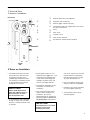
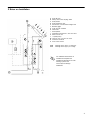
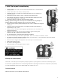
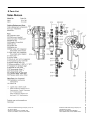
2 Technical Data 3 Notes on Installation Dimensions c d e f k g c d e f Pressure relief valve, 87 psig/6 bar g h i j k Pump Expansion tank connection Pressure gage, 0-6 bar/0-87 psig Temperature gage c/w integrated shut-off valves and flow check valves Flow meter Insulation cover Flush and fill manifold Air separator (located under insulation) j h i 3 Notes on Installation The distance between the SolarDivicon and the collectors must be sufficient because of the possible high temperatures near the collectors. If necessary install an intermediate tank to ensure fittings do not overheat. IMPORTANT Always install Solar-Divicon lower than collector panels to avoid penetration of steam into the expansion tank. If the expansion tank is installed as high or higher than the SolarDivicon, a thermal insulation loop is required. During initial system fill, turn temperature dial gages 45°. This will bypass the integrated flow check valves. After filling and purging is complete return the valve to the original position. Temperature dial gages can be turned 90° to shut off flow completely. Only use bronze-metal, brass and/or copper fittings for the installation. Do not use galvanized pipes or fittings and graphitized gaskets. Do not use any plastic pipes. Components that are in contact with the heat transfer medium (Composition: propylene glycol/water mix (50 %)) must be resistant to it. Prior to installation: Ensure that seals are clean and undamaged. Solar-Divicon must be grounded to protect against lightning. The expansion tank must be checked regularly. IMPORTANT The Solar-Divicon is not suited for direct contact with swimming pool water. 2