1
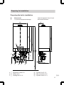
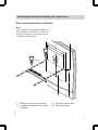
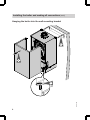
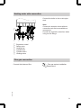
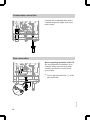
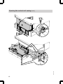
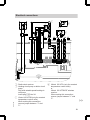
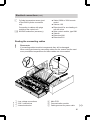
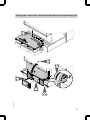
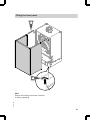
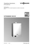
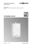
Installation instructions
VIESMANN
for contractors
Vitodens 200-W
Type WB2C, 45 and 60 kW
Wall mounted gas condensing boiler
Natural gas and LPG version
VITODENS 200-W
5457 570 GB
1/2010
Dispose after installation.
Safety instructions
Please follow these safety instructions closely to prevent accidents and material losses.
Safety instructions explained
Danger
This symbol warns against the
risk of injury.
!
■ the Code of Practice of relevant trade
associations,
■ all current safety regulations as
defined by DIN, EN, DVGW, TRGI,
TRF, VDE and all locally applicable
standards.
Please note
This symbol warns against the
risk of material losses and environmental pollution.
Working on the system
Note
Details identified by the word "Note" contain additional information.
Target group
These instructions are exclusively
designed for qualified personnel.
■ Work on gas appliances must only be
carried out by a qualified gas fitter.
■ Work on electrical equipment must
only be carried out by a qualified electrician.
■ Isolate the system from the power supply and check that it is no longer 'live',
e.g. by removing a separate fuse or by
means of a mains isolator.
■ Safeguard the system against unauthorised reconnection.
■ When using gas as fuel, also close the
main gas shut-off valve and safeguard
against unauthorised reopening.
Regulations
5457 570 GB
Observe the following when working on
this system
■ all legal instructions regarding the prevention of accidents,
■ all legal instructions regarding environmental protection,
2
Index
4
5
5
Installation sequence
Installing the boiler and making all connections...................................................
■ Wall mounting bracket installation....................................................................
■ Hanging the boiler into the wall mounting bracket............................................
Heating water side connection.............................................................................
Flue gas connection.............................................................................................
Condensate connection........................................................................................
Gas connection....................................................................................................
Opening the control unit casing............................................................................
Electrical connections...........................................................................................
■ Routing the connecting cables..........................................................................
■ Replacing the boiler coding card for installation in a multi-boiler system..........
Closing the control unit casing and inserting the programming unit.....................
Fitting the front panel............................................................................................
Commissioning and adjustment...........................................................................
7
7
8
9
9
10
10
11
13
15
16
17
19
20
5457 570 GB
Preparing for installation
Product information..............................................................................................
Preparing for installation.......................................................................................
■ Preparing the boiler installation.........................................................................
3
Product information
Vitodens 200-W, WB2C
Set up for operation with natural gas E and LL.
For conversion to LPG P (without conversion kit), see the service instructions.
Conversion for other target countries
The Vitodens 200-W should generally only be delivered to those countries specified
on the type plate. For deliveries to alternative countries, an approved contractor, on
his own initiative, must arrange individual approval in accordance with the law of the
land.
5457 570 GB
Multi-boiler system
In connection with the installation of a multi-boiler system observe the installation
instructions of the multi-boiler system accessories.
For installations in a multi-boiler system, generally the boiler coding card needs to be
replaced (see page 16).
4
Preparing for installation
Preparing the boiler installation
!
Please note
To prevent equipment damage,
install all pipework free of load
and torque stresses.
160
40
1975 N
200
E
K
160
5457 570 GB
B
C
160
D F
1690 O
1166 M
H
A
850
752
L
875
480
P
100
380
G
A Expansion vessel G 1
B Safety valve
C Heating flow G 1½
D Cylinder flow G 1½
E Gas connection R ¾
F Cylinder return G 1½
5
Preparing for installation (cont.)
G
H
K
L
Heating return G 1½
Cable entry area at the back
Accessories (connection sets)
Without connection sets (accessories)
M With connection sets (accessories)
N Recommended dimension (single
boiler system)
O Recommended dimension (multiboiler system)
P Condensate drain
Note
This boiler (protection IP X4 D) is
approved for installation in wet rooms
inside protection area 1 according to
DIN VDE 0100 [Germany], if hosed
water can be prevented.
Observe the requirements of
DIN VDE 0100 [or local regulations].
1. Prepare the water connections. Flush
the heating system thoroughly.
2. Prepare the gas connection according to TRGI or TRF [or local regulations].
5457 570 GB
3. Prepare the electrical connections.
■ Power supply cable: NYMJ 3 x 1.5 mm2, fuse max. 16 A,
230 V~.
■ Accessory cables: NYM with the
required number of conductors for
the external connections.
■ Allow all cables in area "H" to protrude 1200 mm from the wall.
6
Installing the boiler and making all connections
Wall mounting bracket installation
Note
The enclosed screws and rawl plugs are
only suitable for concrete. For other construction materials, use fixings that are
suitable for 100 kg loads.
A
48
0
1.
2
Ø 10
1975 D
2.
42
B
C Top edge finished floor
D Recommendation
5457 570 GB
A Reference point: boiler top edge
B Installation template (included with
the boiler)
C
7
Installing the boiler and making all connections (cont.)
Hanging the boiler into the wall mounting bracket
3.
2.
1.
5457 570 GB
2x
8
Heating water side connection
Connect the boiler to the on-site pipework.
Note
Connection situation shown with the
connection sets that are available as
accessories.
Provide the required connections when
using on-site fittings.
A
B
A
B
C
D
E
F
C
D
E
F
Expansion vessel
Safety valve
Heating flow
Cylinder flow
Cylinder return
Heating return
Flue gas connection
Flue gas system installation
instructions.
5457 570 GB
Connect the balanced flue.
9
Condensate connection
Connect the condensate drain with a
constant slope and a pipe vent to the
public sewer.
Gas connection
Notes regarding operation with LPG
We recommend the installation of an
external safety solenoid valve when
installing the boiler in rooms below
ground level.
1. Seal in gas shut-off valve A at the
gas connection.
5457 570 GB
A
10
Gas connection (cont.)
2. Carry out a tightness test.
Note
For the tightness test, use only suitable and approved leak detecting
agents (EN 14291) and devices.
Leak detecting agents with unsuitable constituents (e.g. nitrites, sulphides) can lead to material damage.
Remove residues of the leak detecting agent after testing.
!
3. Vent the gas line.
Conversion to other gas types:
Service instructions
Please note
Excessive test pressure may
damage the boiler and the gas
valve.
Max. test pressure 150 mbar.
Where higher pressure is
required for tightness tests,
separate the boiler and the
gas valves from the gas supply pipe (undo the fitting).
Opening the control unit casing
Please note
Electronic modules can be damaged by electrostatic discharges.
Before beginning work, touch
earthed objects, such as heating
or water pipes, to discharge static
loads.
5457 570 GB
!
11
Opening the control unit casing (cont.)
3.
2. 2x
1.
5.
5457 570 GB
4. 8x
12
Electrical connections
B
C
A
L1
2
1
D
5
145 145
20 N L
96 N L1 L N 40
230V~
5457 570 GB
X4
7 6 5 4 32 1
X3
100 35
A Radio clock receiver
B Heating circuit pump or boiler circuit
pump
Only with variable speed heating circuit pump:
Insert plug aVG into X4.
C Vitotrol 100 UTDB (only for constant
temperature control units).
When making this connection,
remove jumper between "1" and
"L".
20
230V~
96
40
D Vitotrol 100 UTA (only for constant
temperature control units)
or
Vitotrol 100 UTDB-RF wireless
receiver.
When making this connection,
remove jumper between "1" and
"L".
13
Electrical connections (cont.)
Information regarding the connection of accessories
For the connection, observe the
separate installation instructions
provided with the accessory components.
230 V~ plugs
sÖ Circulation pump
fÖ Power supply [terminals]
Danger
Incorrect core termination
can cause severe injuries
and damage to the equipment.
Take care not to interchange
wires "L1" and "N".
■ Install an isolator in the power
supply line that simultaneously
isolates all non-earthed conductors from the mains with at least
3 mm contact separation.
We additionally recommend
installing an AC/DC-sensitive
RCD (RCD class B
) for
DC (fault) currents that can occur
with energy-efficient equipment.
■ Max. fuse rating 16 A.
lH ■ Power supply accessories (230 V/
50 Hz). Where the boiler is installed in a wet area, the connection
of accessories to the power supply must not be carried out at the
control unit. The power supply
connection for accessories can be
made immediately at the control
unit, if the boiler is installed outside wet areas. This connection is
directly controlled with the system
ON/OFF switch (max. 3 A).
■ Vitotrol 100 UTA
■ Vitotrol 100 UTDB
■ Vitotrol 100 UTDB-RF
Low voltage plugs
! Outside temperature sensor (only
for weather-compensated control
units).
5457 570 GB
?
Installation:
■ North or north-western wall, 2 to
2.5 m above ground level; in
multi-storey buildings, in the
upper half of the second floor
■ Not above windows, doors or
ventilation outlets
■ Not immediately below balconies or gutters
■ Never render over
■ 2-core lead, max. 35 m length
with a cross-section of 1.5 mm2
Flow temperature sensor for low
loss header (accessories)
14
Electrical connections (cont.)
%
Cylinder temperature sensor (part
of the DHW cylinder connection
set).
Connection to cables with plugs
outside of the control unit.
aVG KM BUS subscriber (accessory)
■ Vitotrol 200A or 300A remote
control
■ Vitocom 100
■ Extension kit for one heating circuit with mixer
■ Solar control module, type SM1
■ Vitosolic
■ Extension AM1
■ Extension EA1
Routing the connecting cables
!
Please note
If connecting cables touch hot components they will be damaged.
When routing and securing connecting cables on site, ensure that the maximum permissible temperatures for these cables are not exceeded.
5457 570 GB
5
A Low voltage connections
B 230 V connections
C Internal extension
D Main PCB
E Communication module
F Cable grommet for power cable
15
Electrical connections (cont.)
% Plugs for connecting the cylinder
temperature sensor to the cable harness
Remove the existing cable grommet
when using larger cross-sections (up to
714 mm). Secure the cable with cable
grommet F (black) integrated into the
casing base.
Replacing the boiler coding card for installation in a multi-boiler
system
Corresponding installation
instructions are supplied with the
boiler coding card.
5457 570 GB
If this boiler is installed in a multi-boiler
system, always replace the fitted boiler
coding card with the equivalent card for
multi-boiler systems.
The boiler coding card for multi-boiler
systems is secured at the cover panel
behind the control unit.
16
Closing the control unit casing and inserting the programming unit
1.
2.
3. 2x
6.
5.
5457 570 GB
4.
17
Closing the control unit casing and inserting… (cont.)
Insert programming unit (packed separately) into the control unit support.
Note
The programming unit can also be used
in a wall mounting base (accessory) near
the boiler.
5457 570 GB
Wall mounting base installation
instructions
18
Fitting the front panel
1.
2.
2.
2x
5457 570 GB
Note
Ensure the locking screws are screwed
in before operating.
19
Commissioning and adjustment
20
Viessmann Limited
Hortonwood 30, Telford
Shropshire, TF1 7YP, GB
Telephone: +44 1952 675000
Fax: +44 1952 675040
E-mail: [email protected]
5457 570 GB
Viessmann Werke GmbH&Co KG
D-35107 Allendorf
Telephone: +49 6452 70-0
Fax: +49 6452 70-2780
www.viessmann.com
Subject to technical modifications.
chlorine-free bleached paper
Printed on environmentally friendly,
For commissioning and adjustment, see service instructions.