1
CONNECTION
MOUNTING RDP-01
1.Disconnect power supply by the phase fuse, the circuit-breaker or the
switch-disconnector combined to the
proper circuit.
2.Check if there is no voltage on connection cables by means of a special measure equipment.
3.Connect the cables with the terminals in accordance with the installing
diagram.
4.Install RDP-01 device in installation
cable box.
5.Switch on the power supply from the
mains.t
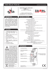
1-CHANNEL RADIO DIMMER RDP-01
ZAMEL Sp. z o.o.
ul. Zielona 27, 43-200 Pszczyna, Poland
tel. +48 (32) 210 46 65, fax +48 (32) 210 80 04
www.zamelcet.com, e-mail: [email protected]
DESCRIPTION
CAPACITY
250W
100W
50W
100W
Radio dimmer RDP-01 cooperates
with light bulbs, compact fluorescent
lamps powered by electronic or toroidal power supply transformers. The device has different functions: a traditional
lighting dimmer function, time control
functions (staircase time delay switch),
comfort functions (memory of adjusted
luminous density level).
APPLICATION
MANUAL INSTRUCTION
TECHNICAL DATA
RDP-01
Input (supply) terminals: L, N
Input rated voltage: 230 V AC
Input voltage tolerance: -15 ÷ +10 %
Nominal frequency: 50 / 60 Hz
Nominal power consumption: 0,5 W
Number of operation modes: 5
Number of channels: 1
Transmission: radio 868,32 MHz
Radio dimmer RDP-01
operating as a receiver
of 4-channel button
radio transmitter RNK04 (switch on/switch off
control, lighting source
brightening/dimming).
The above mentioned
transmitters can also
control operation of
radio lighting switch
RWL-01.
Transmission way: unidirectional
FEATURES
● cooperation with wireless EXTA FREE
system transmitters,
● light sources switching on/switching
off, brightening/dimming,
● cooperation with light bulbs, compact
fluorescent lamps powered by electronic
or toroidal power supply transformers,
● memory of adjusted luminous density
level,
● easy installed in Ø60 mm junction box,
● wide opertaion range (up to 230 m),
● operation is optically signalled,
● low current consumption, possibility of
constant work
● possibility of widening operation range
by means of RTN-01 retansmitter.
Coding: addressing transmission
Maximum number of transmitters: 32
Range: up to 230 m in the open area
Time adjustment: 1 sec ÷ 18 hours (every 1 sec.)
Sygnalizacja optyczna pracy: LED red diode
Receiver’s output clamps:
,N
Maximum output load: 250 W
Number of terminal clamps: 4
Section of connecting cables: up to 2,5 mm2
Ambient temperature range: -10 ÷ +55 oC
Operating position: free
Casing mounting: installation cable box Ø60 mm
Casing protection degree: IP20 (EN 60529)
Protection level: II
Overvoltage category: II
Pollution degree: 2
Surge voltage: 1 kV (EN 61000-4-5)
Dimensions:: 47,5 x 47,5 x 20 mm
Weight: 0,040 kg
Reference standard: EN 60669, PN 60950, PN 61000
The ZAMEL company
devices which are
characterised with this sign
can cooperate with each other.
WARRANTY CARD
There is 24 months guarantee on the product
1. ZAMEL provides a two-year warranty for its products.
2. The ZAMEL warranty does not cover: a) mechanical defects resulting from transport, loading / unloading or other circumstances
b) defects resulting from incorrect installation or operation of ZAMEL products; c) defects resulting from any changes made by CUSTOMERS or third parties, to products sold or equipment necessary for the correct operation of products sold; d) defects resulting
from force majeure or other aleatory events for which ZAMEL is not liable; e) power supply (batteries) to be equipped with a device
in the moment of sale (if they appear);
3. All complaints in relation to the warranty must be provided by the CUSTOMER in writing to the retailer after discovering a defect.;
4. ZAMEL will review complaints in accordance with existing regulations.;
5. The way a complaint is settled, e.g. replacement of the product, repair or refund, is left to the discretion of ZAMEL.
6. Guarantee does not exclude, does not limit, nor does it suspend the rights of the PURCHASER resulting from the discrepancy
between the goods and the contract.
Salesman stamp and signature, date of sale
The device is designed for
single-phase installation and
must be installed in accordance with standards valid in a
particular country. The device
should be connected accordCAUTION! ing to the details included in
this operating manual. Installation, connection
and control should be carried out by a qualified
electrician staff, who act in accordance with the
service manual and the device functions.
In case of casing dismantling an electric shock
may occur, and the guarantee is lost then. Before
installation make sure the connection cables are
not under voltage. The cruciform head screwdriver 3,5 mm should be used to instal the device. Improper transport, storage, and use of the device
influence its wrong functioning. It is not advisable
to instal the device in the following cases: if any
device part is missing or the device is damaged
or deformed. In case of improper functioning of
the device contact the producer.
APPEARANCE
Receiver’s input (supply) terminals (
, N)
Input (supply) terminals (L, N)
Optic signalling of receiver’s operation
Programming push-button
The symbol means selective
collecting of electrical and electronic
equipment. It is forbidden to put
the used equipment together with
other waste.
VER. 003_20.05.2011
OPERATION
TIME PROGRAMMING
RDP-01 can operate in five modes:
COMFORT
(Available only in cooperation with 4 push-button
transmitter). In this mode the
following two functions are
realised:
ONE PUSH-BUTTON
Pressing the programmed
push-button shortly (<0.8
sec.) causes the dimmer
to operate in the range of
switch on/switch off (to the
last adjustment of lighting luminous
density level), however pressing the
programmed push-button longer (>0.8
sec.) causes alternate lighting brightening - dimming.
95%
TWO PUSH-BUTTONS
SWITCH ON pushbutton: pressing the pro-
grammed push-button shortly
(<0.8 sec.) causes the lighting switches on according to
the last adjustment of lighting luminous
density level, however pressing the
programmed push-button longer (>0.8
sec.) causes lighting brightening to the
maximum level.
SWITCH OFF pushbutton: pressing the
0%
level
memory
level
memory
level
memory
programmed push-button
shortly (<0.8 sec.) causes the
lighting switches off, however
pressing the programmed push-button
longer (>0.8 sec.) causes lighting dimming to the minimum level.
1s
TIME
The
device
after
pressing the pushbutton switches on
according to the adjusted time (tp), then it
switches off automatically. Another
pressing of the push-button during
time countdown causes the lighting is switched off before adjusted
time finishes.
Default settings - 15 seconds.
CAUTION! Adjusted time cannot
be deleted.
Press PROG push-button of RDP-01 device for a longer time till
LED red diode switches on (constant signal). Next release PROG
push-button. Wait (for about 5 seconds) till LED red diode switches
on (first signal pulsates, next the signal is constant).
2s
ns
Press PROG push-button of RDP-01
device and then release it.
LED red diode switches off and then
switches on (signal pulsates). Every LED
diode pulse equals 1 second.
After the adjusted time is
finished (the number of LED
red diode flashes) press
PROG push-button and then
release it - TIME IS ADDED.
Maximum time is 18 hours.
REMOTE CONTROLS DELETION
level
memory
level
memory
Press PROG push-button of RDP-01 device
for a longer time.
level
memory
After 5 seconds LED red diode
switches on (signal pulsates)
and then it switches off.
Release the push-button in RDP-01 MEMORY IS DELETED.
COOPERATION AND OPERATING RANGE
REMOTE CONTROLS PROGRAMMING
COMFORT mode:
Press RNK-04
Press PROG push-button of RDP-01 device
transmitter’s
for a longer time until LED red diode switches on
push-button for
(constant signal). Next release PROG push-button
a longer time.
ONE PUSH-BUTTON mode:
Release transmitter’s pushbutton. LED red diode switches
on (first signal pulsates, next
the signal is constant).
Press the same transmitter’s pushbutton and release it. LED red diode
switches on (the signal pulsates) and
next it switches off - THE TRANSMITTER IS ADDED.
Symbol
ROP-01
ROP-02
ROB-01
SRP-02
SRP-03
ROM-01
ROM-10
RDP-01
RTN-01
RNK-02
180 m
200 m
200 m
200 m
200 m
RWG-01 RWL-01
250 m
180 m
250 m
250 m
180 m
250 m
RNK-04
180 m
200 m
200 m
200 m
200 m
250 m
180 m
250 m
250 m
180 m
250 m
P-256/8
230 m
250 m
250 m
250 m
250 m
300 m
200 m
300 m
300 m
230 m
300 m
P-257/4 (2)
180 m
200 m
200 m
200 m
200 m
250 m
180 m
250 m
250 m
180 m
250 m
RNM-10
230 m
250 m
250 m
250 m
250 m
300 m
200 m
300 m
300 m
230 m
300 m
RNP-01
160 m
180 m
180 m
180 m
180 m
200 m
160 m
200 m
200 m
160 m
200 m
RNP-02
160 m
180 m
180 m
180 m
180 m
200 m
160 m
200 m
200 m
160 m
200 m
RNL-01
160 m
180 m
180 m
lack*
lack*
200 m
160 m
200 m
200 m
160 m
200 m
RTN-01
200 m
200 m
200 m
200 m
200 m
250 m
200 m
250 m
250 m
200 m
250 m
RCR-01
160 m
180 m
180 m
lack*
lack*
200 m
160 m
200 m
200 m
160 m
200 m
RTI-01
160 m
180 m
180 m
180 m
180 m
200 m
160 m
200 m
200 m
160 m
200 m
RXM-01
230 m
250 m
250 m
250 m
250 m
300 m
200 m
300 m
300 m
230 m
300 m
* - 1-channel transmitters do not cooperate with roller blind controllers.
CAUTION: The given range concerns open area - an ideal condition without any natural or artificial obstacles. If there are some obstacles between a transmitter and a receiver,
it is advisable to decrease the range according to: wood and plaster: from 5 to 20 %, bricks: from 10 to 40 %, reinforced concrete: from 40 to 80 %, metal: from 90 to 100%,
glass: from 10 to 20 %, Over- and underground medium and high electrical power lines, radio and television transmitters, GSM transmitters set close to a device system have
also a negative influence on the range.
Press PROG push-button of RDP-01 device
for a longer time until LED red diode switches on
(constant signal). Next release PROG push-button.
SWITCH ON/SWITCH OFF mode (two push-buttons):
Press PROG push-button of RDP-01 device for
a longer time until LED red diode switches on
(constant signal). Next release PROG push-button.
TIME mode (one push-button):
Press PROG push-button of RDP-01 device for
a longer time till LED red diode switches on
(constant signal). Next release PROG push-button.
Press the transmitter’s push-button
for a longer time. LED red diode
switches on (first signal pulsates,
next the signal is constant).
Press and release transmitter’s
first push-button. LED red diode
switches on (first signal pulsates,
next the signal is constant).
Press and then release transmitter’s
push-button.LED red diode
switches on (first signal pulsates,
next the signal is constant).
Release transmitter’s push-button. LED
red diode switches on (the signal pulsates),
next the LED red diode switches off - it
means the TRANSMITTER IS ADDED.
Press and release the second transmitter’s
push-button. LED red diode switches on
(the signal pulsates) and next it switches
off - THE TRANSMITTER IS ADDED.
Press and release the same transmitter’s
push-button. LED red diode switches on
(signal pulsates) and then switches off THE TRANSMITTER IS ADDED.
CAUTION: Every transmitter can cooperate with RDP-01 in a different mode, depending on how they were added to the device.
One transmitter can be added during one programming cycle. Full memory is signalled with pulsating LED red diode.
TRANSMITTERS
RECEIVERS
RNK-02
2–channel button
radio transmitter
RNL-01
Radio
foot transmitter
ROP-01
1-channel
radio receiver
RWL-01
Radio lighting
switch
RNK-04
4-channel button
radio transmitter
RTI-01
IR/EXTA FREE
transceiver
ROP-02
2-channel
radio receiver
RWG-01
Remote control
socket
P-256/8
8-channel
remote controller
RNM-10
4-channel radio
modular transmitter
RDP-01
1-channel
radio dimmer
SRP-02
Radio roller blinds
controller
P-257/4
4-channel
remote controller
RNP-01
4-channel
radio transmitter
ROB-01/12-24V
Radio
gate controller
SRP-03
Central radio roller
blinds controller
P-257/2
2-channel
remote controller
RNP-02
4-channel
radio transmitter
ROM-01
1-channel radio
modular receiver
ROM-10
2-channel
radio modular receiver
RCR-01
Radio
motion sensor
RXM-01
Translator
RS-485/EXTA FREE
ACCESSORIES
ANT-01
External antenna
RTN-01
Retransmitter
VER. 003_20.05.2011