1
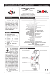
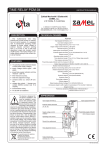
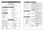
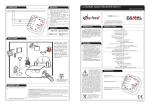
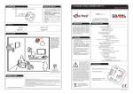
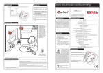
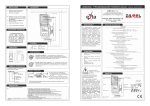
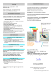
LIGHT DIMMER DIM - 10 INSTRUCTION MANUAL Zakład Mechaniki i Elektroniki ZAMEL sp.j. J.W. Dzida, K. Łodzińska ul. Zielona 27, 43-200 Pszczyna, Poland Tel. +48 (32) 210 46 65, Fax +48 (32) 210 80 04 www.zamel.pl, e-mail: [email protected] DESCRIPTION TECHNICAL PARAMETERS DIM - 10 The device DIM-10 is used to control the bulb lighting level. The unipolar button is responsible for the control. The buttons connected in a parallel way enable lighting operating from different places. The system has the control switch on/off function and smooth brightening/dimming the light. The system enables intelligent lighting system control and gives comfort and economy in use. Input (supply) terminals: L, N Input rated voltage: 230 V~ Input voltage tolerance: from -15 to +10 % Nominal frequency: 50 / 60 Hz Rated power consumption: 41 mA Supply voltage control indicator: LED green Release terminals: IN, IN, IN Lighting control: unipolar connector Output (load) terminals: N, Output switch on indicator: LED red Charging power: from 30 to 400 W Controlling element: triak 400 VA FEATURES Number of terminal clamps: 11 Section of connecting cables: from 0,2 to 2,50 mm2 یIntelligent lighting control, Ambient temperature range: from -20 to +45 oC Operating position: free یbulb lighting level control, Mounting: rail TH35 (PN-EN 60715) یinput rated indicator, Protection degree: IP20 (PN-EN 60529) یoutput (load) switch on indicator, Protective class: II Overvoltage category: II یcooperation with unipolar pushbuttons equipped with neon light, Pollution degree: 2 Rated impulse withstand voltage: 1 kV (PN-EN 61000-4-5) یmaximum power load - 400 VA, Dimensions (height / width / depth): doublemodule (35 mm) 90x35x66 mm یdoublemodule casing, Weight: 125 g یTH-35 DIN rail installation. The device is designed for one-phase installation and must be installed in accordance with standards valid in CAUTION a particular country. The device should be connected according to the details included in this operating manual. Installation, connection and control should be carried out by a qualified electrician staff, who act in accordance with the service manual and the device functions. Disassembling of the device is equal with a loss of guarantee and can cause electric shock. Before installation make sure the connection cables are not under voltage. The cruciform head screwdriver 3,5 mm should be used to instal the device. Improper transport, storage, and use of the device influence its wrong functioning. It is not advisable to instal the device in the following cases: if any device part is missing or the device is damaged or deformed. In case of improper functioning of the device contact the producer. Reference standards: PN-EN 60669-1; PN-EN 60669-2-1 PN-EN 61000-4-2,3,4,5,6,11 APPEARANCE Input (supply) terminals (L) Relay system terminals (IN, IN, IN) Input (supply) terminals (N) L Supply voltage indicator N IN IN I N Output (load) switch on indicator Input (supply) terminals (N, N, N, , , ) ver. 0.4.2 _ 2006.06.20_11:00 1. Disconnect the power supply from the mains by the phase fuse, the circuit-breaker or the switch-disconnector that are joined to the proper circuit, 2. Check if there is no voltage on connection cables by means of a special measure equipment, 3. Install ASM-10 device in the switchboard on TH-35 DIN rail, 4. Connect the cables with the terminals according to installing diagram, 5. Switch on the power supply from the mains. The system is used to control the lighting with a total power that does not exceed 400 VA. The unipolar button is responsible for the control. The buttons connected in a parallel way enable lighting operating from different places. Short pressing and releasing the button (for about 0,8 s) causes the lighting switch over in the switch on/off sequence. Short pressing of the button causes the bulb switches on with full power if they are switched off; the next short pressing causes a total switch off. Holding the button for a longer time (>0,8 s) causes smooth, alternate illuminating / dimming. After the input voltage and the lighting is switched off the adjusted level is not remembered. DIMENSIONS CONNECTING TIME COURSE ... MOUNTING, FUNCTIONING INNER DIAGRAM L RELAY CAPACITY IN IN IN N N µC EXAMPLE OF INSTALLATION PRODUCT FAMILY DIM-10 light dimmer belongs to Dix light dimmers.. Typical application: The lighting dimmer system controls the lighting in a room by means of unipolar pushbuttons installed on the walls. GUARANTEE CARD There is 24 months guarantee on the product Salesman stamp and signature, date of sale 1. ZAMEL provides a two-year warranty for its products. 2. The ZAMEL warranty does not cover: a) mechanical defects resulting from transport, loading / unloading or other circumstances, b) defects resulting from incorrect installation or operation of ZAMEL products, c) defects resulting from any changes made by CUSTOMERS or third parties, to products sold or equipment necessary for the correct operation of products sold, d) defects resulting from force majeure or other aleatory events for which ZAMEL is not liable. 3. All complaints in relation to the warranty must be provided by the CUSTOMER in writing to the retailer after discovering a defect. 4. ZAMEL will review complaints in accordance with existing regulations. 5. The way a complaint is settled, e.g. replacement of the product, repair or refund, is left to the discretion of ZAMEL. ver. 0.4.2 _ 2006.06.20_11:00