1
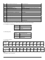
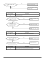
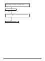
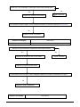
CONTENTS
1. General information of Outdoor Units ................................................................................................... 3
2. Dimensions .............................................................................................................................................. 4
3. Wiring Diagram ........................................................................................................................................ 5
4. Refrigeration Cycle Diagram .................................................................................................................. 7
5. Indoor units combination ....................................................................................................................... 8
6. Electronic control function..................................................................................................................... 9
7. Troubleshooting .................................................................................................................................... 14
1. General information of Outdoor Units
Outdoor unit
Power relay control
Low noise air flow system
Hydrophilic aluminum fin
The hydrophilic fin can improve the heating efficiency at operation mode.
4 way valve control
It is only operated in the heating operation mode except defrosting operation.
Anti-rust cabinet
Valve protection cover
It protects the valves and prevents water from dripping.
Discharge pipe temperature protection
Compressor crankcase heater
2. Dimensions
a)320+;
b) 320+;
3. Wiring Diagram
3.1 320+;
3.2 320+;
3.3 320+;
4. Refrigeration Cycle Diagram
4.1 Refrigeration circuit drawing of inverter binary type
Axial flow fan
EXVA
Exhaust
temp. sensor
Main
Capillary
Auxiliary
Capillary
Filter A
Liquid valve A
Filter B
Liquid valve B
Capillary A
EXVB
Condenser
4-way
valve
Check
Valve
Coil temp.
sensor
Evaporator
Cross
Indoor pipe out
temp. sensor A
Gas valve A
Indoor pipe out
temp. sensor B
Compressor
Gas valve B
Indoor Unit
Outdoor Unit
4.2
flow fan
Capillary B
Refrigeration circuit drawing of inverter trinary type
Axial flow fan
Main
Capillary
Exhaust
temp. sensor
Condenser
4-way
valve
Coil temp.
sensor
Auxiliary
Capillary
Check
Valve
Capillary A
EXV A
Capillary B
EXV B
Liquid valve A
Filter A
Liquid valve B
Filter B
Capillary C
EXV C
Liquid valve C
flow fan
Evaporator
Filter C
Cross
Compressor
Indoor pipe out
temp. sensor A
Gas valve A
Indoor pipe out
temp. sensor B
Gas valve B
Indoor pipe out
temp. sensor C
Gas valve C
Outdoor Unit
4.3 Refrigeration circuit drawing of inverter quadplex type
Indoor Unit
5. Indoor units combination
5.1 Indoor unit combination for 320+;
One unit
Two unit
9
9+9 9+12
12
5.2 Indoor unit combination for 320+;
One unit
Two unit
9
9+9
12
12+12
Three unit
9+12 9+9+9 9+9+12
5.3 Indoor unit combination for 320+;
One unit
Two unit
9
9+9
12
12+12
9+12
Three unit
9+9+9
9+9+12
9+12+12
12+12+12
Four unit
9+9+9+9
9+9+9+12
9+9+12+12
6. Electronic control function
6.1 Abbreviation
T1: Indoor ambient temperature
T2:
Coil temperature of indoor heat exchanger middle.
T2B: Coil temperature of indoor heat exchanger outlet.
T3:
Coil temperature of outdoor heat exchanger
T4:
Outdoor ambient temperature
T5:
Compressor discharge temperature
Ts: Setting temp.
6.2 Electric control working environment.
6.2.1 Input voltage: 230V.
6.2.2 Input power frequency:60Hz.
6.2.3 Indoor fan normal working amp. is less than 1A.
6.2.4 Outdoor fan. Normal working amp. is less than 1.5A.
6.2.5 Four-way valve normal working amp. is less than 1A.
6.2.6 Swing motor: DC12V.
6.3 Outdoor unit’s digital display tube
There is a digital display tube in outdoor PCB.
Digital display tube display function
•
In standby , the LED displays “- -”
•
In compressor operation, the LED display the running frequency,
•
In defrosting mode, The LED displays “dF” or alternative displays between running frequency and
“dF”(each displays 2s)
•
In compressor pre-heating, The LED displays “- -”
•
In protection or malfunction, the LED displays error code or protection code.
6.4 Outdoor unit point check function
There is a check switch in outdoor PCB.
Push the switch SW1 to check the states of unit when the unit is running. The digital display tube will display
the follow procedure when push SW1 each time.
Display
Remark
1
Indoor unit capacity demand code
2
Outdoor unit running mode code
3
Amendatory capacity demand code
4
Outdoor unit fan motor state
Off:0, Low speed:1, High speed:2
5
Evaporator outlet temp. for 1# indoor unit
Actual data
6
Evaporator outlet temp. for 2# indoor unit
Actual data
7
Evaporator outlet temp. for 3# indoor unit
Actual data
8
Evaporator outlet temp. for 4# indoor unit
Actual data
9
Condenser pipe temp.
Actual data
10
Ambient temp.
Actual data
11
Compressor discharge temp.
Actual data
12
Inverter current
Actual data
13
EXV open angle for 1# indoor unit
Actual data divide 8
Off:0, Cooling:1, Heating:2
14
EXV open angle for 2# indoor unit
Actual data divide 8
15
EXV open angle for 3# indoor unit
Actual data divide 8
16
EXV open angle for 4# indoor unit
Actual data divide 8
17
18
19
Power supply of outdoor unit
Indoor unit number
The last error or protection code
AD data
The indoor unit can communicate with outdoor unit well.
00 means no malfunction
20
frequency value
Actual data
21
Ambient temp. of 1# indoor unit
Actual data
22
Condenser pipe temp. of 1# indoor unit
Actual data
23
Ambient temp. of 2# indoor unit
Actual data
24
Condenser pipe temp. of 2# indoor unit
Actual data
25
Ambient temp. of 3# indoor unit
Actual data
26
Condenser pipe temp. of 3# indoor unit
Actual data
27
Ambient temp. of 4# indoor unit
Actual data
28
Condenser pipe temp. of 4# indoor unit
Actual data
29
――
Check point over
The following items from 6.4.1 to 6.4.6 are for the explanation of the point check functions.
6.4.1 Frequency of compressor:
Display
Frequency of compressor (Hz)
30
30
--
Stand by
60
60
Display
Corresponding mode
0
Off
1
Cooling mode
2
Heating mode
6.4.2 Running mode:
6.4.3 Capacity demand:
Cooling mode
Capacity
2000-2
500
2000-2
500
3000-3
800
4500-5
000
5000-5
500
5500-6
100
6100-7
000
7000-7
500
7500-8
000
>7500
Correspondi
ng Code
1
2
3
4
5
6
7
8
9
>=10
Heating mode
Capacity
2000-2
500
2000-2
500
3000-3
800
4500-5
000
5500-6
100
6100-7
000
6100-7
000
7000-7
500
7500-8
000
>8000
Correspondin
g Code
1
2
3
4
5
6
7
8
9-10
>=11
Note:
The capacity is just for reference.
6.4.4Number of indoor unit
Display
Number of indoor unit
1
1
2
2
3
3
6.4.5 Outdoor ambient temp:
Display
Corresponding temp.
Display
Corresponding
temp.
Display
Corresponding
temp.
15
-7.5
50
10
80
25
16
-7
51
10.5
81
25.5
17
-6.5
52
11
82
26
18
-6
53
11.5
83
26.5
19
-5.5
53
11.5
84
27
20
-5
54
12
85
27.5
21
-4.5
55
12.5
86
28
22
-4
56
13
87
28.5
23
-3.5
57
13.5
88
29
24
-3
58
14
89
29.5
26
-2
59
14.5
90
30
27
-1.5
60
15
91
30.5
28
-1
61
15.5
92
31
29
-0.5
62
16
93
31.5
30
0
63
16.5
93
31.5
31
0.5
63
16.5
94
32
32
1
64
17
95
32.5
33
1.5
65
17.5
96
33
34
2
65
17.5
97
33.5
35
2.5
66
18
98
34
36
3
67
18.5
99
34.5
37
3.5
68
19
10.
35~40
38
4
69
19.5
11.
40~45
39
4.5
70
20
12.
45~50
40
5
71
20.5
13.
50~55
41
5.5
72
21
14.
55~60
42
6
73
21.5
15.
60~65
43
6.5
74
22
16.
65~70
44
7
75
22.5
45
7.5
75
22.5
46
8
76
23
47
8.5
77
23.5
48
9
78
24
49
9.5
79
24.5
6.4.6 Opening degree of electronic expansion valve:
Actual opening degree equals the display data divided 8
6.5 Protection
6.5.1 Three minutes delay at restart for compressor.
6.5.2 Temperature protection of compressor discharge.
When the compressor discharge temp. is getting higher, the running frequency will be limited as below rules:
----If 102℃<T5<115℃, decrease the frequency to the lower level every 2 minutes till to F1.
---If T5>115℃ for 10 seconds, the compressor will stop and restart till T5<90℃.
6.5.3 Low voltage protection
VOLTAGE
VOLREL1
No limit
VOLLIMT1
VOLFRE1
VOLREL2
VOLLIMT2
VOLFRE2
VOLREL3
VOLLIMT3
Off
Model
320+;
VOLLIMT1
230
VOLLIMT2
VOLLIMT3
VOLREL1
VOLREL2
VOLREL3
VOLFRE1
VOLFRE2
200
120
260
210
135
62
54
32M3+;
245
220
120
265
240
135
78
45
POM365HX
200
185
120
210
195
135
54
42
Note: if the low voltage protection occurs and not resumes within 3min, it will keep the protection always
after restart the machine.
6.5.4 Compressor current limit protection
If the compressor current exceeds the current limit value for 10 seconds, the compressor frequency will be
limited as below table.
Cooling mode:
Current frequency(Hz)
Current limit value(A)
COOL_F10
ICOOLLMT6
COOL_F9
ICOOLLMT5
COOL_F8
ICOOLLMT4
COOL_F7
ICOOLLMT3
COOL_F6
ICOOLLMT2
COOL_F5
ICOOLLMT1
Frequency limit
Decrease the frequecny to COOL_F4 and run at
COOL_F4 for 3 minutes.
After that,the frequency will be adjusted according to the
capacity demand and rise to the upper level every 3
minutes
(When the frequency>COOL_F4 via capacity demand).
If the current frequency is lower than COOL_F4, the frequency will not be limited.
After 10s of the compressor start, if the current>ICOOL,the AC will display the failure for 30 seconds and stop. The AC will restart 3
minutes later.
Heating mode:
Current frequency(Hz)
Current limit value(A)
Frequency limit
HEAT_F12
IHEATLMT8
HEAT_F11
IHEATLMT7
Decrease the frequency to HEAT_F4 and run at HEAT_F4
for 3 minutes.
HEAT_F10
IHEATLMT6
HEAT_F9
IHEATLMT5
HEAT_F8
IHEATLMT4
After that, the frequency will be adjusted according to the
capacity demand and rise to the upper level every 3
minutes
HEAT_F7
IHEATLMT3
HEAT_F6
IHEATLMT2
HEAT_F5
IHEATLMT1
(When the frequency>Heat_F4 via capacity demand).
If the current frequency is lower than HEAT_F4, the frequency will not be limited.
After 10s of the compressor start, if the current>IHEAT,the AC will display the failure for 30 seconds and stop. The AC will restart 3
minutes later.
6.5.5 Indoor / outdoor units communication protection
If the indoor units can not receive the feedback signal from the outdoor units for 2 minutes, the AC will stop
and display the failure.
6.5.6 High condenser coil temp. protection.
When T3>65℃ for 3 seconds, the compressor will stop while the indoor fan and outdoor fan will continue.
When T3<52℃, the protection will release and the compressor will restart after 3 minutes.
6.5.7 Outdoor unit anti-freezing protection
When T2B<0℃ for 250 seconds, the indoor unit capacity demand will be zero and resume to normal when
T2B>10℃.
6.5.8 Oil return
Running rules:
1. If the compressor frequency keeps lower than RECOILINFRE for 2hours,the AC will rise the frequency
to RECOILFRE for 3mins and then resume to former frequency.
Model
POM182HX
2.
RECOILINFRE
45
POM273HX
45
POM365HX
40
During the oil return process, the EXV and indoor units keep the current running mode, the frequency
will not be limited by the compressor discharge temp. and the current.
6.5.9 Compressor preheating functions
----Preheating permitting condition:
If T4(outdoor ambient temperature)<3℃ and newly powered on or if T4<3℃ and compressor has stopped
for over 3 hours, the compressor heating cable will work.
----Preheating mode:
A weak current flow through the coil of compressor from the wiring terminal of compressor, then the
compressor is heated without operation.
----Preheating release condition:
If T4>5℃ or the compressor starts running, preheating function will stop.
6.5.10 Compressor crankcase heater
When T4<3℃ and the compressor is not running,the crankcase heater will be active.
When T4≧5℃ or the compressor starts up,the crankcase heater will stop work.(For M5OA-36HRDN1-Q,T4
≧8℃)
7. Troubleshooting
7.1 Indoor unit error code explanation:
Vertu series:
Display
E0
LED STATUS
EEPROM error
E1
Communication error between indoor and outdoor unit
E2
Zero-crossing examination error
E3
Fan speed beyond control
E5
Outdoor units temp. sensor or connector of temp. sensor is defective
E6
Indoor units temp. sensor or connector of temp. sensor is defective
P0
Inverter module protection
P1
Outdoor voltage too low protection
P2
Compressor discharge temp. protection
P3
Outdoor temp. too low protection
P4
Compressor driving protection
7.2 Outdoor unit error code explanation:
Display
LED STATUS
E0
EEPROM error
E1
No 1 Indoor units pipe temp. sensor or connector of pipe temp. sensor is defective
E2
No 2 Indoor units pipe temp. sensor or connector of pipe temp. sensor is defective
E3
No 3 Indoor units pipe temp. sensor or connector of pipe temp. sensor is defective
E6
No 4 Indoor units pipe temp. sensor or connector of pipe temp. sensor is defective
E4
Outdoor temp. sensor or connector of temp. sensor is defective
E5
Compressor volt protection
E7
Communication error between outdoor IC and DSP
P0
Compressor discharge temp. protection
P1
High pressure protection (just for 36K 1x4 units.)
P2
Low pressure protection (just for 36K 1x4 units.)
P3
Compressor current protection
P4
Inverter module protection
P5
Outdoor temp. too low protection
P6
Condenser high-temperature protection
P7
Compressor driving protection
PF
PFC protection
7.3Trouble shooting
7.3.1 Indoor unit trouble shooting
Indoor unit display
LED STATUS
E0
EEPROM error
Replace indoor PCB
Circuit or software error on indoor PCB
Indoor unit display
LED STATUS
E1
outdoor communication error
Disconnect the power supply, after 1 minute,
connect the power supply, turn on the unit with
remote controller
Does
the
normally ?
unit
work
NO
Check the wiring between
indoor and outdoor unit. Is
the connection of L, N, S and
GND good?
NO
Reconnect and retest again
Is the GND connection on
outdoor PCB good?
Yes
Is the LED4(red) on
outdoor PCB bright and
LED1(yellow) blinking?
Yes
Replace indoor PCB
and repower on. Is
the failure cleared?
No
The power supply for
outdoor PCB is fail. Check
the wiring on outdoor PCB
comparing with wiring plate.
Is the connection good?
Yes
No
Replace outdoor e-box.
Correct the connection.
Indoor unit display
LED STATUS
E2
Zero-crossing examination error
NO
Is power supply
and
connection of connectors
good?
Be sure the power supply is good
and correct the connection
YES
Indoor PCB is defective. Replace
the indoor PCB.
Indoor unit display
E3
LED STATUS
Fan speed beyond control
Is the indoor fan motor
connector and connection
good?
NO
Repair the connector and
reconnect
YES
Is voltage being applied to
the fan motor?
YES
Indoor PCB is defective.
Replace the indoor PCB.
(rang 90v-160v between
mid pin and N on CN1
NO
Replace
motor
Indoor unit display
E5
the
indoor
LED STATUS
Outdoor units temp. sensor or connector of temp. sensor is defective
Is the outdoor temperature
sensor
connector
and
connection good?
NO
Repair the connector and
reconnect
YES
Replace the sensor and
check if E5 display again?
Indoor unit display
E6
fan
YES
Replace outdoor e-box
LED STATUS
Indoor units temp. sensor or connector of temp. sensor is defective
Is the indoor temperature
and evaporator sensor
connector and connection
good?
NO
Repair the connector and
reconnect
YES
Replace the sensor and
check if E6 display again?
YES
Indoor unit display
Replace the.indoor PCB
LED STATUS
P0
Inverter module protection
NO
Is voltage normal?
Revise the power and retest.
YES
Is all connection good?
NO
Revise the power and retest.
YES
Is the wiring to compressor
right?
YES
Check the modular if some
components blow out or be
failure?
YES
Repair or replace the modular.
YES
Is it breakdown between
P-N, P-V, P-W, N-V,N-W or
V-W of inverter moduler?
YES
Replace the modular.
YES
Check the compressor.
Indoor unit display
P1
LED STATUS
Outdoor voltage protection
NO
Is the power supply good?
Be sure the power supply is
normal when using the units
YES
Replace the outdoor e-box.
Indoor unit display
P2
Does compressor
operate?
LED STATUS
Compressor top protection against temperature
NO
YES
Is the connection
good?
NO
Reconnect and retest.
YES
Is
refrigerant
circulation
volume normal?
Is
protector
normal?
NO
Replace the protector.
YES
NO
Check the outdoor
main PCB. Is there
some problem?
Charge refrigerant
YES
Replace the outdoor PCB.
Is abnormality
the same after
gas charging?
NO
Check
refrigerant
system
(such as clogging of capillary,
Indoor unit display
P3
LED STATUS
Compressor current protection
The trouble shooting is same with one of outdoor unit P3 protection.
8.4.1 Outdoor unit trouble shooting
Outdoor unit display
LED STATUS
E0
EEPROM error
Circuit or software error on indoor
Outdoor unit display
E1
Replace
indoor
LED STATUS
No 1 Indoor units pipe temp. sensor or connector of pipe temp. sensor is
defective
Is connection to connector of pipe temp. sensor good?
No
Yes
Repair connector
Check the resistance of the temp. sensor according to Annex 1
Replace the sensor
LED STATUS
Outdoor unit display
E2
No 2 Indoor units pipe temp. sensor or connector of pipe temp. sensor is
defective
Is connection to connector of pipe temp. sensor good?
No
Yes
Repair connector
Check the resistance of the temp. sensor according to Annex 1
Replace the sensor
LED STATUS
Outdoor unit display
E3
No 3 Indoor units pipe temp. sensor or connector of pipe temp. sensor is
defective
Is connection to connector of pipe temp. sensor good?
No
Yes
Repair connector
Check the resistance of the temp. sensor according to Annex 1
Replace the sensor
Outdoor unit display
LED STATUS
E6
No 4 Indoor units pipe temp. sensor or connector of pipe temp. sensor is
defective
Is connection to connector of pipe temp. sensor good?
No
Yes
Repair connector
Check the resistance of the temp. sensor according to Annex 1
Replace the sensor
Outdoor unit display
LED STATUS
E4
Outdoor units temp. sensor or connector of temp. sensor is defective
Is connection to connector of pipe temp. sensor good?
No
Yes
Repair connector
Check the resistance of the temp. sensor according to Annex 1
Replace the sensor
LED STATUS
Outdoor unit display
E5
Compressor volt protection
Check the voltage of power supply, if the voltage is about 220V, turn off the
power supply to indoor unit and turn it on again after 1 minute
Does the trouble occur again?
Yes
Check the voltage of secondary of T3 transformer in outdoor power board ,
is this voltage 12-14V(AC)
No
Replace the outdoor power board
LED STATUS
Outdoor unit display
E7
outdoor units communication protection
Is the LED in outdoor main PCB light?
Yes
Check the signal wires between outdoor
PCBs, is it connected good.
No
No
1.Is the +5 voltage in outdoor main board?
Power Board: CN4, Red wire and yellow (GND)
Outdoor main PCB: CZ1
2.Is the +3.3v voltage in outdoor main board?
Power Board: CN1, Purple wire and yellow (GND)
Inverter module defective.
Rectifier circuit is bad connection or
defective when the voltage in outdoor is
abnormal .
D and N: 310V(DC);
Yes
Check the IC6, IC7 (at Outdoor power PCB)
Normally:
Input voltage: <5V, changeable
Output voltage:<5V, changeable
No
Outdoor power PCB is defective.
Outdoor unit display
LED STATUS
P0
Compressor top protection against temperature
Off: 105c;
On: 90c
The trouble shooting is same with the one of indoor unit P2 protection.
LED STATUS
Outdoor unit display
P3
Compressor current protection
Check the resistance of compressor, normally
U and V is 1 ohm
U and W is 1 ohm
V and W is 1ohm
No
The compressor is defective
No
Turn one indoor unit only, Does the compressor start after
3 minutes?
Yes
No
The compressor is defective
Does the trouble occur again after compressor
running some time?
Yes
Check the refrigerant circulation volume and pressure
If refrigerant circulation volume and pressure is OK, change the outdoor main PCB.
Outdoor unit display
P4
LED STATUS
Compressor drive malfunction(drive protection arose)
Are the U,V,W connected to compressor and inverter module right?
No
Yes
Repair connector
Replace the outdoor power board
If the problem comes to again, check wingding resistance of inverter compressor, is it 1 ohm?
No
Replace inverter compressor
LED STATUS
Outdoor unit display
P4(LED flashes for nine times)
Compressor drive malfunction(module protection arose)
Are the U,V,W connected to compressor and inverter module
Yes
No
Replace the module to see if it is normal?
Repair connector
Replace the outdoor power board
If the problem comes to again, check wingding resistance of inverter compressor, is it right?
No
Replace inverter compressor
Outdoor unit display
LED STATUS
P6
Condenser high-temperature protection
When outdoor pipe temp. is more than
temp. less than 52°C.
65°C, the unit will stop, and unit runs again when outdoor pipe
Is the outdoor pipe temp. more than 65°C ?
No
Is the outdoor pipe temp sensor right according to the annex 1
Yes
No
Replace the outdoor main board
Replace the outdoor pipe temp sensor
Annex 1
Characteristic of temp. sensor
Temp.℃
Resistance KΩ
Temp.℃
Resistance KΩ
Temp.℃
Resistance KΩ
-10
62.2756
17
14.6181
44
4.3874
-9
58.7079
18
13.918
45
4.2126
-8
56.3694
19
13.2631
46
4.0459
-7
52.2438
20
12.6431
47
3.8867
-6
49.3161
21
12.0561
48
3.7348
-5
46.5725
22
11.5
49
3.5896
-4
44
23
10.9731
50
3.451
-3
41.5878
24
10.4736
51
3.3185
-2
39.8239
25
10
52
3.1918
-1
37.1988
26
9.5507
53
3.0707
0
35.2024
27
9.1245
54
2.959
1
33.3269
28
8.7198
55
2.8442
2
31.5635
29
8.3357
56
2.7382
3
29.9058
30
7.9708
57
2.6368
4
28.3459
31
7.6241
58
2.5397
5
26.8778
32
7.2946
59
2.4468
6
25.4954
33
6.9814
60
2.3577
7
24.1932
34
6.6835
61
2.2725
8
22.5662
35
6.4002
62
2.1907
9
21.8094
36
6.1306
63
2.1124
10
20.7184
37
5.8736
64
2.0373
11
19.6891
38
5.6296
65
1.9653
12
18.7177
39
5.3969
66
1.8963
13
17.8005
40
5.1752
67
1.830
14
16.9341
41
4.9639
68
1.7665
15
16.1156
42
4.7625
69
1.7055
16
15.3418
43
4.5705
70
1.6469
Annex 2
1. Reference voltage data:
a)
Rectifier : Input :220-230V(AC), output :310V(DC)
b)
Inverter module: U,V, W 3ph.
Result
U-V
60-150V(AC)
U-W
60-150V(AC)
V-W
60-150V(AC)
P-N
DC
31
0V
c)
Photo-couple PC817, PC851:
Control side <+5V, AC side :< 24V(AC)
d)
S terminal and N: changeable from 0-24V
2. Check the Diode Bridge component ( In wiring diagram, rectifier)
Remark: If this part is abnormal, the LED will not light.
~
+
-
~
Result
Multi-meter
+
~
~
-
_
+
~
~
Forward Resistance
Backward Resistance
Infinite
Infinite
~500 ohm
Infinite
~500 ohm
Infinite