1
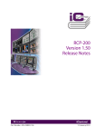
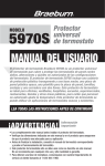
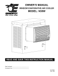
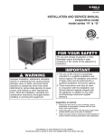
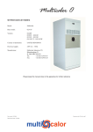
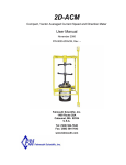
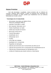
INSTALLATION SERVICE MANUAL
IIEVC-6
J30-05401
OUTDOOR ROOFTOP EVAPORATIVE COOLING UNITS
*Unit Type (EV) - Capacity (CA) - (10-40)
Evaporative Cooling systems meet a wide range of heating and ventilating requirements. The Evaporative Cooler
may be purchased as an individual unit in four sizes from 800 CFM to 8500 CFM (0.4 to 4.0 m3/s) or, it can be
combined with Rooftop Packaged Units (Natural or Power Vented), Air Handlers, or Make-up Air Handlers. In any
combination, the Evaporative Cooler will replace the need for 100% Outside Air Inlet Hood.
Evaporative Cooling is the simplest and most-cost effective cooling method without the use of mechanical
refrigeration.
FPO
ATTENTION: Read This manual IIEVC, manuals RISM* and RBM*, submittal/data sheets,
and all labels attached to the unit carefully before attempting to install, operate, or service the Evaporative Cooling Unit! Retain this manual for future reference.
Maintain water in sumps by proper microbicidal water treatment to minimize the risks of illness caused by Legionella Pneumophila (the bacteria that causes
Legionnaire's Disease) and other bacteria. Refer to local codes regarding any additional
treatment or restrictions regarding water supplies and usage.
INSTALLER'S RESPONSIBILITY
Installer Please Note: This equipment has been tested and inspected. It has been shipped
free from defects from our factory. However, during shipment and installation, problems such as
loose wires, leaks or loose fasteners may occur. It is the installer's responsibility to inspect
and correct any problems that may be found.
The model and serial numbers are located on the data plate attached to the side of the cooler.
Record this information in the spaces provided below.
Model No.
*This manual may also be used for the following:
Unit Types (UT) - (RT or PV)
Rooftop Arrangements (RA) - (D or E) and
Unit Type (UT) - (AH)
Rooftop Arrangements (RA) - (P or R)
Capacity (CA) - (20 or 40)
Serial No.
260 NORTH ELM ST., WESTFIELD, MA 01085
TEL: (413) 568-9571 FAX: (413) 562-8437
www.mestek.com
RECEIVING INSTRUCTIONS
Inspect shipment immediately after receiving to determine
if any damage has occurred during shipment If any
damage is found, the consignee should sign the bill of
lading, indicating such damage, and immediately file claim
for damage with the transportation company.
The following terms are used throughout this manual, in
addition to the other requirements, to bring attention to the
presence of potential hazards or to important information
concerning the product:
Indicates an imminently hazardous
situation which, if not avoided, will result in
death, serious injury or substantial property
damage.
TABLE OF CONTENTS
Description
Page
General Information ...........................................Cover, 2
PERFORMANCE & SPECIFICATION DATA
Evaporative Cooler - Dimensional
& Performance Data .............................................. 3
CELdek® Media Data and Efficiency Chart ............. 3
Gas-Fired Rooftop Packaged Units
with Evaporative Cooler .................................... 4, 5
Air Handler with Evaporative Cooler......................... 6
PARTS IDENTIFICATION ............................................ 7
INSTALLATION
Mounting to Roof ...................................................... 8
Connecting Water Supply ......................................... 8
Faucet Use ............................................................... 8
Adjusting Water Level and Float Valve ..................... 9
Adjusting Water Flow ................................................ 9
Bleed-Off .................................................................. 9
Electrical Connections ...................................... 10, 11
MAINTENANCE
Maintenance Schedule ........................................... 12
Changing Media ................................................ 12, 13
Cleaning Water Pump ............................................. 13
Washing Media ........................................................ 13
Washing Inlet Filter .................................................. 13
Cabinet Cleaning and Touch-up .............................. 13
Winter Shut-Down ................................................... 13
Evaporative Cooler Curb Assembly Diagram .......... 14
Model Number Description ...................................... 15
Replacement Parts .................................................. 15
Indicates an imminently hazardous
situation which, if not avoided, could result in
death, serious injury or substantial property
damage.
Indicates an imminently hazardous
situation which, if not avoided, may result in minor
injury or property damage.
NOTICE: Used to notify of special instructions on
installation, operation, or maintenance which are
important to equipment but not related to personal
injury.
Failure to comply with the General Safety Information
may result in extensive property damage, severe
personal injury, or death.
GENERAL SAFETY INFORMATION
Unless otherwise specified, the following conversions may
be used for calculating SI/metric unit measurements:
1 lb. = 0.453 kg
1 cubic foot = 0.028m3
1000 Btu per hour = 0.293 kW
1 foot = 0.305 m
1 inch water column = 0.249 kPa
1 inch = 25.4 mm
1 gallon = 3.785 L
1 psig = 6.894 kPa
1000 BTU/cu. ft. = 37.5 MJ/m3
1liter/second = CFM x 0.472
meter/second = FPM ÷ 196.8
–2–
Disconnect all power before
installing or servicing the unit. If power disconnect
is out of sight, lock it in the open position and tag
it to prevent unexpected application of power.
Failure to do so could result in fatal electrical
shock or severe personal injury.
Do not alter the unit in any way, or
damage to the unit and/or severe personal injury
or death may occur.
Do not depend on a thermostat or
other switch as a sole means of disconnecting
power when installing or servicing unit. Always
disconnect power at the main circuit breaker as
described above. Failure to do so could result in
fatal electrical shock.
PERFORMANCE AND SPECIFICATION DATA
Evaporative Cooling Units
Figure 1
S
Capacity
A
10/15
32-7/8"
(835)
20/25/50
30/35
43-7/8"
(1114)
60/70
54-7/8"
(1394)
40/80
36"
(914)
Water
Distribution
Assembly
“A”
2" CELdek®
Liquid Tight
Electrical
Tubing
Bleed-off
Ball
Valve
Intake
Filter
Junction Box
60-3/8"
(1534)
43"
(1092)
Pump
Overflow
8" CELdek®
(Optional 12")
4"
(102)
1/4" Water
Inlet
3/4" NPT
Drain
(Capped)
S
Float Valve
SECTION S-S
Table 1 (Refer to individual unit submittals for more specifications.)
Performance and Dimensional Data
*Capacity
10,15
20, 25, 50
30, 35, 60, 70
40, 80
CFM
(cu. m/s) (cu. m/s)
MIN.
MAX.
800
4,500
(0.378)
(2.124)
1,600
5,500
(0.755)
(2.596)
2,400
8,500
(1.133)
(4.012)
3,200
8,500
(1.510)
(4.012)
8" Saturation
Efficiency
Range
MIN.
MAX.
78
77
77
77
88
88
86
86
12" Saturation
Efficiency
Range
MIN.
MAX.
89
88
88
87
92
92
92
92
8" or 12" Media
Face Area
Size
Ft.2
in.
(m2)
(mm)
Pressure Drop
in W.C.
(kPa)
(kPa)
MIN.
MAX.
“A” Unit
Width
in.
(mm)
Shipping
Wt.
lb.
(kg)
Operating
Wt.
lb.
(kg)
7.01
31 x 32-9/16
0.03
0.23
32-3/4
137
301
(0.65)
(787 x 827)
(0.01)
(0.06)
(832)
(62)
(136)
9.38
31 x 43-9/16
0.03
0.20
43-3/4
166
386
(0.87)
(787 x 1106)
(0.01)
(0.05)
(1111)
(75)
(175)
11.75
31 x 54-9/16
0.05
0.30
54-3/4
192
468
(1.09)
(787 x 1386)
(0.01)
(0.07)
(1391)
(87)
(212))
12.92
31 x 60
0.07
0.28
60-1/4
206
509
(1.20)
(787 x 1524)
(0.02)
(0.07)
(1530)
(93)
(231)
*Capacities - (50, 60, 70 and 80) are for Dual Furnace Unit Types only.
Figure 2
0.5
100%
12"
Evap
orativ
e Co
oling
12"
Efficie
8"
80%
0.3
8"
70%
0.2
P
Air
60%
200
300
400
res
sur
ro
eD
p
0.1
500
Air Velocity - FPM
–3–
0.4
ncy
600
700
800
Air Pressure Drop Inches - WG
90%
Evaporative Cooling Efficiency
CELdek® EVAPORATIVE MEDIA
The Evaporative Cooler utilizes high efficiency
CELdek® media. CELdek® is made from a special
cellulose paper, impregnated with insoluble antirot salts and rigidifying saturants. The cross fluted
design of the pads induces highly-turbulent mixing
of air and water for optimum heat and moisture
transfer. The evaporative coolers are available
with standard 8 or optional 12 inch media which
produce high efficiency and high face velocities,
along with a 2" distribution pad to disperse the
water evenly over the pads.
Rooftop Packaged Unit
with Evaporative Cooling
Figure 3 - Natural Vent Rooftop Unit with Evaporative Cooler (without Supply Plenum)
36"
(914)
1" (25)
Typ.
§ U (Capacities 50/80)
A
C (Typ. Sq.)
§ U (Capacities 10/40)
CL
Vent Caps
Are Shipped
In Separate
Cartons
D
Evaporative
Cooler
19"
39"
(483)
Discharge (991)
Opening
1-1/8" (29)
Typ. Duct
Flange
10-1/8"
(257)
6-1/16"
(154)
5/8" (16) Typ.
Anchor Hole
Location
D4163
T4160BD
18-7/8" (479)
x J Typ.
O.S. Damper
Opening
Electrical
Connections
Gas
Connection
26"
(660)
B
Discharge
Opening
8-3/4
(222)
6-1/2"
(165)
*
§L
G
Outside
F
5"
1" (25)
(127)
Curb Cap
1-5/16" (33) Typ.
Anchor Hole
Location
Table 2A
CAPACITY
10
15
20
25
30
35
40
50
60
70
80
A
32-7/8
(835)
32-7/8
(835)
43-7/8
(1114)
43-7/8
(1114)
54-7/8
(1394)
54-7/8
(1394)
60-3/8
(1534)
43-7/8
(1114)
54-7/8
(1394)
54-7/8
(1394)
60-3/8
(1534)
B
15-9/16
(395)
18-5/16
(465)
23-13/16
(605)
29-5/16
(745)
34-13/16
(884)
40-5/16
(1024)
45-13/16
(1164)
29-5/16
(745)
34-13/16
(884)
40-5/16
(1024)
45-13/16
(1164)
C
12
(305)
21-1/2
(546)
23-1/2
(597)
23-1/2
(597)
26
(660)
26
(660)
26
(660)
23-1/2
(597)
26
(660)
26
(660)
26
(660)
A.G.A.
D
11
(279)
16
(406)
16
(406)
16
(406)
17-1/2
(445)
17-1/2
(445)
17-1/2
(445)
16
(406)
17-1/2
(445)
17-1/2
(445)
17-1/2
(445)
C.G.A.
D
20-11/16
(525)
25-3/16
(640)
25-3/16
(640)
25-3/16
(640)
26-11/16
(678)
26-11/16
(678)
26-11/16
(678)
25-3/16
(640)
26-11/16
(678)
26-11/16
(678)
26-11/16
(678)
*F
19-3/8
(492)
23-1/2
(597)
26-1/4
(667)
34-1/2
(876)
37-1/4
(946)
45-1/2
(1156)
51
(1295)
34-1/2
(876)
37-1/4
(946)
45-1/2
(1156)
51
(1295)
G
31-1/16
(789)
31-1/16
(789)
42-1/16
(1068)
42-1/16
(1068)
53-1/16
(1348)
53-1/16
(1348)
58-9/16
(1487)
42-1/16
(1068)
53-1/16
(1348)
53-1/16
(1348)
58-9/16
(1487)
▲J
24
(610)
24
(610)
35
(889)
35
(889)
46
(1168)
46
(1168)
51-1/2
(1308)
35
(889)
46
(1168)
46
(1168)
51-1/2
(1308)
L
77-3/8
(1965)
77-3/8
(1965)
77-3/8
(1965)
77-3/8
(1965)
77-3/8
(1965)
77-3/8
(1965)
77-3/8
§U
72-1/4
(1835)
72-1/4
(1835)
72-1/4
(1835)
72-1/4
(1835)
72-1/4
(1835)
72-1/4
(1835)
72-1/4
(1965)
(1835)
103-3/8
(2626)
103-3/8
(2626)
103-3/8
(2626)
103-3/8
(2626)
98-1/4
(2496)
98-1/4
(2496)
98-1/4
(2496)
98-1/4
(2496)
GAS INLET
NAT
LP
1/2
1/2
1/2
1/2
1/2
1/2
3/4
1/2 OR 3/4
3/4
1/2 OR 3/4
3/4
1/2 OR 3/4
3/4
1/2 OR 3/4
3/4
1/2 OR 3/4
3/4
1/2 OR 3/4
3/4
1/2 OR 3/4
3/4
1/2 OR 3/4
NOTE: REFER TO UNIT SUBMITTALS FOR MORE SPECIFICATIONS/UNIT ARRANGEMENTS.
DIMENSIONS ARE IN INCHES, DIMENSIONS IN PARENTHESIS ARE IN MILLIMETERS.
* “F” DIMENSION IS THE RECOMMENDED CLEARANCE TO SERVICE THE BURNER DRAWER(S).
▲“J” DIMENSION IS AN OUTSIDE DIMENSION FOR RETURN AIR DAMPERS.
§ “U” ALL DIMENSIONS ARE TABULATED FOR ROOFTOP ARRANGEMENTS B & D PER CAPACITIES 10 THROUGH 80 ACCORDINGLY
(CAPACITIES 50/80 ARE SHOWN PICTORIALLY).
NATURAL VENT UNIT DIMENSIONS SHOWN ABOVE; FOR POWER VENT DIMENSIONS, CONTACT CUSTOMER SERVICE FOR POWER
VENT UNIT SUBMITTAL SHEETS.
–4–
Rooftop Packaged Unit
with Evaporative Cooling
Figure 4 - Natural Vent Rooftop Unit with Evaporative Cooler (with Supply Plenum)
36"
(914)
§U
A
26"
(660)
26"
(660)
C (Typ.) Sq.
CL
Vent Caps
Are Shipped
In Separate
Cartons
Evaporative
Cooler
D
39"
(991)
6-1/16"
(154)
5/8" (16) Typ.
Anchor Hole
Location
D4165
T4160CE
18-7/8" (479) Lifting
x J Typ. Brackets
O.S. Damper
Opening
Electrical
Connections
Gas
Connection
6-1/2"
(165)
§R
§Q
26"
(660)
18-7/8" (479)
x J Typ.
Inside
Opening
1" (25)
Curb Cap
3-9/16"
(90)
6-1/16"
(154)
34-3/4"
(883)
J Inside
Supply Opening
*
F
G
Outside
§L
5"
(127)
1-5/16" (33) Typ.
Anchor Hole
Location
Table 2B
CAPACITY
10
15
20
25
30
35
40
50
60
70
80
A
32-7/8
(835)
32-7/8
(835)
43-7/8
(1114)
43-7/8
(1114)
54-7/8
(1394)
54-7/8
(1394)
60-3/8
(1534)
43-7/8
(1114)
54-7/8
(1394)
54-7/8
(1394)
60-3/8
(1534)
C
12
(305)
21-1/2
(546)
23-1/2
(597)
23-1/2
(597)
26
(660)
26
(660)
26
(660)
23-1/2
(597)
26
(660)
26
(660)
26
(660)
A.G.A.
D
11
(279)
16
(406)
16
(406)
16
(406)
17-1/2
(445)
17-1/2
(445)
17-1/2
(445)
16
(406)
17-1/2
(445)
17-1/2
(445)
17-1/2
(445)
C.G.A.
D
20-11/16
(525)
25-3/16
(640)
25-3/16
(640)
25-3/16
(640)
26-11/16
(678)
26-11/16
(678)
26-11/16
(678)
25-3/16
(640)
26-11/16
(678)
26-11/16
(678)
26-11/16
(678)
*F
19-3/8
(492)
23-1/2
(597)
26-1/4
(667)
34-1/2
(876)
37-1/4
(946)
45-1/2
(1156)
51
(1295)
34-1/2
(876)
37-1/4
(946)
45-1/2
(1156)
51
(1295)
G
31-1/16
(789)
31-1/16
(789)
42-1/16
(1068)
42-1/16
(1068)
53-1/16
(1348)
53-1/16
(1348)
58-9/16
(1487)
42-1/16
(1068)
53-1/16
(1348)
53-1/16
(1348)
58-9/16
(1487)
▲J
24
(610)
24
(610)
35
(889)
35
(889)
46
(1168)
46
(1168)
51-1/2
(1308)
35
(889)
46
(1168)
46
(1168)
51-1/2
(1308)
L
103-3/8
(2626)
103-3/8
(2626)
103-3/8
(2626)
103-3/8
(2626)
103-3/8
(2626)
103-3/8
(2626)
103-3/8
(2626)
129-5/16
(3285)
129-5/16
(3285)
129-5/16
(3285)
129-5/16
(3285)
Q
NA
R
NA
NA
NA
NA
NA
NA
NA
NA
NA
NA
NA
NA
NA
58-3/4
(1492)
58-3/4
(1492)
58-3/4
(1492)
58-3/4
(1492)
38-5/8
(981)
38-5/8
(981)
38-5/8
(981)
38-5/8
(981)
§U
98-1/4
(2496)
98-1/4
(2496)
98-1/4
(2496)
98-1/4
(2496)
98-1/4
(2496)
98-1/4
(2496)
98-1/4
(2496)
124-1/4
(3156)
124-1/4
(3156)
124-1/4
(3156)
124-1/4
(3156)
NAT
1/2
GAS INLET
LP
1/2
1/2
1/2
1/2
1/2
3/4
1/2 OR 3/4
3/4
1/2 OR 3/4
3/4
1/2 OR 3/4
3/4
1/2 OR 3/4
3/4
1/2 OR 3/4
3/4
1/2 OR 3/4
3/4
1/2 OR 3/4
3/4
1/2 OR 3/4
NOTE: REFER TO UNIT SUBMITTALS FOR MORE SPECIFICATIONS/UNIT ARRANGEMENTS.
DIMENSIONS ARE IN INCHES, DIMENSIONS IN PARENTHESIS ARE IN MILLIMETERS.
* “F” DIMENSION IS THE RECOMMENDED CLEARANCE TO SERVICE THE BURNER DRAWER(S).
▲“J” DIMENSION IS AN OUTSIDE DIMENSION FOR RETURN AIR DAMPERS.
▲“J” DIMENSION IS ALSO AN INSIDE DIMENSION FOR SUPPLY AIR (WITHOUT DAMPER).
§ “U” ALL DIMENSIONS ARE TABULATED FOR ROOFTOP ARRANGEMENTS C & E PER CAPACITIES 10 THROUGH 80 ACCORDINGLY
(CAPACITIES 50/80 ARE SHOWN PICTORIALLY).
NATURAL VENT UNIT DIMENSIONS SHOWN ABOVE; FOR POWER VENT DIMENSIONS, CONTACT CUSTOMER SERVICE FOR POWER
VENT UNIT SUBMITTAL SHEETS.
–5–
Air Handler Packaged Unit
with Evaporative Cooling
Figure 5 - Standard Air Handler with Evaporative Cooler (without Supply Plenum)
72"
(1829)
36"
(883)
A
1" (25) Typ.
Duct Flange
Evap.
Cooler
Intake
Filter
19" (483)
x B
Discharge
Opening
6-1/16"
(154)
39"
(991)
10-1/8"
(257)
Water
Inlet 1/4"
3/4" Npt Drain
(Capped)
Overflow
5/8" (16) Typ.
Anchor Hole
Location
18-7/8" (479)
x J Typ.
Damper
Opening
6-1/2"
(165)
D3666B
T3672FR
Electrical
Connections
1" (25)
Curb Cap
5"
(154)
51-1/2"
(1306)
Table 3
CAPACITY
A
B
C
G
▲J
20
43-7/8"
23-13/16"
21-15/16
42-1/16"
35"
(1114)
(605)
(557)
(1068)
(889)
60-3/8"
45-13/16"
30-3/16"
58-9/16"
51-1/2"
(1534)
(1164)
(767)
(1487)
(1308)
40
NOTE: REFER TO UNIT SUBMITTALS FOR MORE SPECIFICATIONS/UNIT ARRANGEMENTS.
DIMENSIONS ARE IN INCHES, DIMENSIONS IN PARENTHESIS ARE IN MILLIMETERS.
▲ “J” DIMENSION IS AN OUTSIDE DIMENSION FOR RETURN AIR DAMPERS.
▲ “J” DIMENSION IS ALSO AN INSIDE OPENING FOR SUPPLY AIR (WITHOUT DAMPERS)
Figure 6 - Standard Air Handler with Evaporative Cooler (with Supply Plenum)
36"
(883)
A
72"
(1829)
Evap.
Cooler
Intake
Filter
39"
(991)
6-1/16"
(154)
Water
Inlet 1/4"
3/4" NPT Drain
(Capped)
D3667B
T3672FR
Overflow
5/8" (16) Typ.
Anchor Hole
Location
6-1/2"
(165)
18-7/8" (479)
x J Typ.
Damper
Opening
Electrical
Connections
77-3/8"
(1964)
–6–
19" (483)
x J
Discharge
Opening
1" (25)
Curb Cap
6-1/16"
(154)
5"
(127)
EVAPORATIVE COOLER
PARTS IDENTIFICATION
2
3
16
4
15
5
6
14
7
8
9
10
11
13
1. Bulk Head Fitting (Drain Overflow)
2. Water Distribution Assembly
3. Clip Assembly (Water Distribution
Assembly)
4. Ball Valve
5. Line Filter
6. Brass Needle Cock Valve
7. Worm Clamp
8. PVC Flexible Hose
12
1
9.
10.
11.
12.
13.
14.
15.
16.
–7–
Pump Support Bracket
Pump
Poly Tubing - 1/4" O.D.
Pump Basket Screen
Float Valve
Media Pad ( 8" or Opt. 12" W)
Media Distribution Pad (2" x 8" x L or 2" x 12" x L)
Hood Water Distribution
INSTALLATION
This manual is for Evaporative Cooler Module Installations only.
Refer to the Installation and Service Manuals for Rooftop Packaged Units
and Outdoor Furnaces for these unit installations.
Mounting to Roof
1. Before positioning the unit in its permanent
location, make certain that the roof is capable
of carrying the load of this equipment. Note that
when the cooler is filled with water, the unit will be
much heavier than when dry. See “Performance and
Dimension Data” table for appropriate operating
weight.
2. If unit is to be mounted on a curb, refer to the curb
specifications for installation requirements.
3. Make certain that the mounting surface is level in
all directions.
4. Make certain that you have sufficient means for
lifting the unit into place.
5. Installation must conform to local and national
building and safety codes.
6. The units are mounted on skid rails and are suitable
for use on combustible flooring. It is recommended
that the skids be mounted either on solid planking or
on steel channels, but never on a soft tar roof where
the skids could sink and reduce the 4" clearance
between the bottom pan and the roof.
7. Inspect all internal parts of the cooler section to
determine if any damage has occurred during
shipment. See roof curb specifications at the end of
the manual.
Connecting the Water Supply
NOTICE: Soft water equipment should not be
attached to water lines going to the cooler. “Soft
Water” will cause corrosion and decrease the
effective life of the cooler.
Figure 7 - Float Valve Assembly
FLOAT VALVE
ROD LEVEL
ADJUSTMENT SCREW
3-1/4"
NOTICE: There will be a slight odor during the initial
start-up of the unit. The odor will disappear within
the first few days of operation if the bleed-off is
adjusted correctly.
Faucet Use
1. To connect the water line to the water supply, install
a sillcock and water valve on the faucet.
2. Place tubing nut and ferrule on tube end, and insert
valve.
3. Tighten the nuts on the valve and the tube.
NOTICE: If a faucet is not to be used for the water
supply, install the valve on the water line to be used.
Follow the procedure above for securing the tubing
to the valve.
Figure 8 - Evaporative Cooler Water Connections
1. A water valve should be installed at a convenient
location to allow water to be turned on and off. Use
1/4" tubing to supply water to Evaporative Cooler.
A water connector kit is available at your local
wholesaler.
2. Place tube nut and ferrule over the end of the
tubing.
3. Insert tubing into factory-installed float valve and
tighten securely.
BRASS NEEDLE COCK
FAUCET WITH
HOSE BIBB
1/4" TUBING
FROM COOLER
ROOF LINE
NUT AND FERRULE
BRASS STOP COCK
WITH DRAIN
D3870
WATER SUPPLY
–8–
Adjusting the Water Level and Float Valve
Fill the tank as follows:
1. Turn the water supply on. Fill the tank to a depth of
approximately 3.25" (82.6mm). While filling the tank,
check for good pressure and flow from the float
valve.
2. The float valve should shut down the water supply
at the 3.25" (82.6mm) level. It may be necessary to
adjust the float valve by bending the rod. The rod
level adjustment screw should be set in lower notch
on lever.
3. Check the tank and all connections for leaks.
NOTE: The overflow fitting is set so that the water
will begin to flow at the 3.25" (82.6mm) depth. It is
important that the water level not be above the pump
basket screen!
Adjusting the Water Flow
Proper water flow over the media is important.
Insufficient water flow will result in increased
accumulation of minerals on the media. Excessive water
flow will result in deterioration of the media and moisture
carryover.
1. Using the ball valve handle, adjust the water flow so
that the media is damp from the top to the bottom. If
you can see water flowing on the entering side, your
water level is too high. Adjust the valve so that the
media is just damp on the entering side. Repeated
drying of the media will cause rapid buildup of
mineral deposits in the media. Drying is due to
improper adjustment of the water flow valve, frequent
shut-down of the pump to control the evaporative
cooling/humidification, or localized air velocities
across the surface of the media. The area where dry
spots occur will exhibit high mineral deposits. The
valve must be adjusted so that no dry spots appear
on entering or leaving side, and when adjusted
correctly, enough water will flow through the media to
wash out most of the airborne dirt and other debris.
2. Prior to start-up, it is recommended that the tank
be filled, and the pump turned on, allowing the
unit to run for approximately 10 minutes. Repeat
this procedure two times to help flush any dirt that
may have accumulated during shipping.
Bleed-Off
Bleed-Off is required to maintain the water quality of
the system. When water evaporates, minerals and
other impurities are left behind, impurities are scrubbed
from the air flowing through the system, and make-up
water (even good quality make-up water) adds more
minerals and impurities. These form deposits on the
media during the evaporative process.Therefore, it is
important to bleed-off a small quantity of recirculating
water to keep the concentration of impurities under
control. The bleed-off rate required is dependent upon
the quality of the water used and the rate of evaporation.
As climate conditions change, the rate of evaporation
may increase, requiring an increase in the bleed-off rate.
It is recommended that the bleed-off rate be adjusted
for the maximum water evaporation. An indication of
insufficient bleed-off is a uniform build-up of minerals
on the entering air face of the media. If this condition is
observed, increase the rate of bleed-off until the mineral
deposits dissipate.
Adjusting the Bleed-Off
1. The bleed-off is attached to the PVC tee. This
bleed-off system will eliminate a small quantity of
water from recirculation, which will reduce scale
build-up. This water will drain through the attached
tube, and out through the overflow. Disposal of this
water should comply with local codes.
2. Adjust the bleed-off rate according to Table 4.
Table 4
Unit Size
Capacity
–9–
Seconds to Fill
12 oz. Can
10/15
69
46
20/25/50
52
34
30/35/60/70
41
27
40/80
38
25
ELECTRICAL CONNECTIONS
Do not use any tools (i.e. screwdriver,
pliers, etc.) across the terminals to check for power.
Use a voltmeter.
HAZARDOUS VOLTAGE!
DISCONNECT ALL ELECTRIC
POWER INCLUDING REMOTE
DISCONNECTS BEFORE
SERVICING. Failure to
disconnect power before
servicing can cause severe
personal injury or death.
USE COPPER CONDUCTORS ONLY!
UNIT TERMINALS ARE NOT DESIGNED TO ACCEPT
OTHER TYPES OF CONDUCTORS. Failure to do so
may cause damage to the equipment.
Refer to the unit data plate to determine the supply
voltage.
Do not service before disconnecting
power or there could be a potential for an electrical
shock hazard.
The motor name-plate and electrical rating on the
transformer should be checked before energizing the
unit electrical system. All external wiring must conform
to ANSI/NFPA No. 70-1996, National Electrical Code
(or the latest edition of) and applicable local codes; in
Canada, to the Canadian Electrical Code, Part 1 CSA
Standard C22.1
“Dashed” lines represent either field wiring (by others) or
optional equipment. Refer to optional items (shown on wiring diagram included with unit) - these will be hard wired.
Do not jumper factory wiring.
Mis-wiring of safety circuits may result in fire
or death.
It is recommended that the electrical power to each
unit be provided by a separate, fused, and permanently
live electrical circuit. A disconnect switch of suitable
electrical rating for each unit should be placed as close
to the controls as possible. Each unit must be electrically
grounded in accordance with the latest edition of the
National Electrical Code, ANSI/NFPA No. 70-1996, or
CSA Standard C22.1. Sample wiring connections are
depicted in Figures 9 & 10.
NOTICE: Consult the factory before making any
changes to factory wiring.
OPTIONAL FILL AND DRAIN KIT: Optional Evaporative
Cooler Fill and Drain Kit consists of two motorized valves,
installed in the building, and piped and wired to the roof.
The kit eliminates the need to go to the roof to fill or drain
the cooler for seasonal changeover, and automatically
maintains the water level. See sample Figure 10. Refer
to the kit's instruction.
GROUNDING: Install a ground wire to suitable ground
according to local codes.
NOTICE: For all wiring connections, refer to the
wiring diagram shipped with the unit (either affixed
to the side jacket or enclosed in the unit’s installation
instruction envelope). Should any original wire
supplied with the unit have to be replaced, it must be
replaced with wiring material having a temperature
rating of at least 105°C.
– 10 –
ELECTRICAL CONNECTIONS (continued)
Figure 9
Figure 10
– 11 –
MAINTENANCE
d.) Biological Fouling Control:
Uncontrolled growth of organic matter can lead to
plugged media, metal deterioration, and biological contamination of the airstream. Whenever the
possibility of biological contamination of water in
an airstream exists, transmittal of Legionnaire’s
Disease should be addressed. While there are
no reported cases of Legionnaire’s Disease associated with rigid media type evaporative cooling
systems, the Legionella Pneumophila bacteria is
present in almost all water supplies. However, the
mere presence of the bacteria does not create a
hazard: the bacteria must be transmitted as an
aerosol in sufficient densities to be infectious.
Open all disconnect switches
and secure in that position before servicing unit.
Failure to do so may result in personal injury or
death from electrical shock.
Because of the nature of the evaporative process, algae
buildup, biological fouling, scale build-up, and corrosion are
distinct possibilities. Proper water treatment and regularly
scheduled maintenance will minimize or eliminate most
problems.
a.) Cooling Pad Check List:
√ Reduce the number of on/off cycles.
√ Shade the pads and pump.
√ Dry pads out completely once every 24 hours.
√ Maintain a suitable water bleed-off rate.
√ Drain and disinfect the entire water system
quarterly.
√ Avoid harmful contaminants, including dust,
fumes, harsh cleaners, and water treatment
chemicals.
√ Circulate the recommended quantity of
water over the pads.
√ Avoid dry areas on the pads.
√ Clean the filters regularly.
b.) Controlling Algae:
Scale and mineral deposits can form on the
cooling pad because the mineral content of
the water is too high.
Increase the water flow over the face of the pads.
Make certain that the flow of water is even from
one end of the distribution pipe to the other end.
Clean and flush the distributor pipe regularly;
especially if dry areas appear on the pads.
Maintain the pH of the recirculating water
between 6 and 8.
Maintain sufficient bleed-off rate.
For more details, check MUNTERS® Engineering
Bulletin EB-WTM-502 (included with this manual).
c.) Preventing Algae in the Evaporative Pads:
Algae needs light, moisture, and nutrients
to survive. Eliminating, or reducing, these
elements will help to control algae. For specific
details, see MUNTERS® Engineering Bulletin
EB-WTM-502 (included with this manual).
NOTICE: It is highly recommended that the services
of a water treatment company be retained to advise
on the proper treatment of the sump water for
biological, scale, and corrosion control. For more
information, see MUNTERS® Engineering Bulletin
EB-WTM-502 (included with this manual).
Maintenance Schedule
Regular maintenance is the key to successful service from
your Evaporative Cooler. Use the following schedule as a
guide to maintain you unit:
Maintenance
Requirements
Changing Media
Cleaning Water
Pump
Cleaning &
Touch-Up
Adjusting Bleed-Off
Periodic Inspection
Washing Down
Media with Hose
Washing Inlet Filter
with Hose
Drain Unit
Annual
Start-Up
At Beginning of 6th
Year or if Passages
are blocked
Annual
Shut-Down
√
√
√
During Cooling
Season
√
During Cooling
Season
As Required During
Season
√
√
Following are explanations of the procedures outlined in
the above schedule.
Changing the Media
This should be done every 5 years or if passages become
blocked.
1. Remove filter/frame assemblies.
2. Disconnect the water hood panel from the top panel
by removing screws.
3. Snap out water distribution system.
4. Remove top media distribution pad.
5. Liftoutmediasections(Notethepositionofmedia
with respect to airflow. See Figure 11)
– 12 –
6. Replace with new CELdek® media sections. (See
replacement part section).
Aspen and other evaporative media will not work.
7. When re-installing media, be sure all media
sections are installed in the proper direction. See
Figure 11.
8. Replace top media distribution pad, water
distribution system, water hood panel, and filter/frame
assemblies.
Figure 11 - Evaporative Cooling Media Pad Section
45° TYP.
15° TYP.
D3883
R
AI
OW
FL
Cleaning the Water Pump
Do not allow the pump to topple over
or become submerged. Water will damage the pump
motor. This is not a submersible pump.
Disassemble and clean water pump as follows:
1. Disconnect power.
2. Disconnect the liquid tight connector from the
junction box to remove cord and connector.
3. Disconnect the pump mounting bracket and hose.
4. Remove the pump and basket screen.
5. To clean pump, snap out base of the pump; notice
the impeller.
6. Using a mild detergent solution, wash all deposits
from the impeller and the impeller base plate.
7. Spin the impeller to dislodge any foreign material.
Make sure that the impeller spins freely.
8. Carefully snap the impeller and impeller base plate
back onto the pump.
9. Wash the pump basket screen using the same
detergent solution, and rinsing thoroughly to remove
any debris. If unable to clean, replace with a new
screen (See replacement part section).
Washing the Media
Avoid splashing water on the blower
motor at all times (this could cause electrical
problems)!
1. Scale and dust should be washed off the intake side of
the media annually, using a garden hose and nozzle;
this will help to unclog passages.
2. Using a stiff brush, lightly brush the intake edges of
the media. This will not harm the openings, but will
remove any hardened scale.
3. Occasionally, there will be a build-up of algae or odors.
The best solution for both of these problems is to
allow the pads to dry thoroughly on a regular basis.
If cooling is not needed at night during the cooling
season, allow the blower to run for a few hours after
the pump has been shut-down to dry pads daily.
4. During the cooling season, we recommend that
the pads be shut down nightly if possible with the
blower running to dry the pads out for a few hours
before the unit is shut down.
Washing the Inlet Filter
The pre-filter should be cleaned periodically as follows:
1. Turn the four latches and remove filter frame
assemblies.
2. Carefully remove the aluminum filters. Wash the filters
with warm water and a mild soap, rinse thoroughly.
3. Re-install in unit.
4. If the aluminum mesh filters are damaged or cannot
be cleaned, replace the mesh filter (See replacement
parts section).
Cabinet Cleaning and Touch-Up
The cabinet and all internal parts of the Evaporative Cooler
should be cleaned annually using a soft cloth, warm water,
and a mild cleanser.
NOTE: Avoid using steel wool or sandpaper in normal
cleaning of the unit.
Winter Shut Down
1. Clean and flush out Evaporative Cooler media and
sump.
2. Clean water distributor holes.
3. Drain fill pipe and leave open. DO NOT LEAVE ANY
WATER IN THE SYSTEM. FREEZING CAN CAUSE
MAJOR DAMAGE TO THE UNIT.
4. Remove and clean pump if necessary.
5. Check sump tank for leaks and repair if necessary.
Sump tank is fabricated from stainless steel.
NOTICE: The pump motor does not require any
lubrication.
– 13 –
Roof Curb Kit - RC015* (-1, -2, -3, -4)
For use with:
Unit type (UT) - EV
Capacities (CA) - 10/40
*Evaporative Cooler Platform Only
(Included with Roof Curb Kit No's RC002, RC004, RC008, RC012)
Club Platform to Unit Assembly
Approximate Curb Kit
Shipping Weight
Roof Curb Kit RC015
Contents:
Curb Kit No.
Capacity (CA)
RC015-1
10/15
Curb (2 platforms per kit)
RC015-2
20/25/50
3
1/4-20 “KEPS” Nut (8) required
RC015-3
30/35/60/70
RC015-4
40/80
4
1/4-20 x 5/8 LG. Hex HD. Bolt (8) required
1
Evaporative Cooler Assembly (sold separately)
2
1 lb. = 0.453 kg
*One Platform Kit fits All Evaporative Cooler Modules/Capacities (CA) - 10/80
Capacities 50, 60, 70 and 80 are for (RT/PV) unit types only.
– 14 –
Weight (lbs.)
30
How to order Replacement Parts
Please provide the following information to your local representative:
• Model Number
• Serial Number (if any)
• Part Description and Number as shown in Replacement Parts Literature
If further assistance is needed, please contact the manufacturer's customer service department.
Evaporative Cooler Model Number Description
Digit
Item
E
X
X — E
Prefix
(Internal use Only)
V 3* 4* 0
UT
CA
0
0
0
0
0 11* 0
0
FT FM RA CO GT GC SV MT MS
0
AI
0 16* 17* +
AC
AS
*See Model No. Description below.
1, 2 - Unit Type [UT]
14 - Air Inlet Configuration [AI]
EV - Evaporative Cooler Only
0 - None
3, 4 - Capacity [CA]
15 - Air Control & Damper Arrangement [AC]
10 - 100,000 BTU/HR
15 - 150,000 BTU/HR
20 - 200,000 BTU/HR
25 - 250,000 BTU/HR
30 - 300,000 BTU/HR
35 - 350,000 BTU/HR
40 - 400,000 BTU/HR
5 - Furnace Type [FT]
0 - None
16 - Accessories [AS]
C1 - Evap. Cooler - Fill & Drain Kit
C2 - Evap. Cooler - 12" Celdek® Media
C3 - Evap. Cooler - Freezestat
D1 - Time Clock - 7 Day
D2 - Time Clock - 24 Hour
0 - None
6 - Furnace Construction Material [FM]
0 - None
7 - Rooftop Arrangement [RA]
0 - None
8 - Coil Options [CO]
0 - None
9 - Gas Type [GT]
0 - None
10 - Gas Control [GC]
0 - None
11 - Supply Voltage [SV]
1 - 115/1/60
2 - 208/1/60
3 - 230/1/60
12 - Motor Type [MT]
E2 - G.F.I. Convenience Outlet 115VAC
E3 - Remote Control Panel
F1 - Ductstat - One Stage
F2 - Ductstat - Two Stage
G1 - Thermostat - T87F w/Subbase
G2 - Thermostat - T87F w/Subbase & Guard
G3 - Thermostat - T834H w/Subbase (Sterling Stat)
G4 - Thermostat - T7300 - 7 Day Programmable
G5 - Thermostat - T874 (Two Stage)
H1 - Return Firestat
H2 - Supply Firestat
H3 - Freezestat
L1 - 30 Amp, Fused Disconnect Switch
L2 - 30 Amp, Non Fused Disconnect Switch
L3 - 60 Amp, Fused Disconnect Switch
L4 - 60 Amp, Non Fused Disconnect Switch
0 - None
13 - Motor Sizes [MS]
0 - Other (Specify)
0 - None
LIMITED WARRANTY
The complete unit is warranted by the manufacturer to be free from defects in material and workmanship for a
period of one (1) year from the date of manufacture.
The manufacturer will repair or replace, at its option, any component which, upon inspection, it finds to be
defective, provided that the unit has been operated within its listed capacity, has been installed in accordance with
the furnished instructions, has not been misused or subjected to negligence and has received reasonable and
necessary maintenance. The warranty does not cover labor costs or other costs incurred in repairing, removing,
installing, servicing or handling of parts or completed products.
The warranty does not cover loss due to corrosion by chemicals precipitated in the air such as halogenated
hydrocarbons. The manufacture will in no event be liable for incidental or consequential damages of any kind
whatsoever.
Written permission is required prior to the return of defective components. All returns must be sent with all
transportation charges prepaid to the plant designated in the written permission.
This warranty is extended only to the original owner of the unit.
– 15 –
260 NORTH ELM ST., WESTFIELD, MA 01085
TEL: (413) 568-9571 FAX: (413) 562-8437
www.mestek.com