1
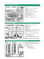
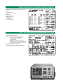
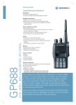
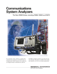
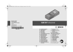
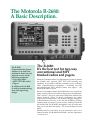
The Motorola R-2680:
A Basic Description.
The R-2680
Communications System
Analyser is a radio test
instrument that tests and
performs service on the
following equipment:
• Two-way radios
• MPT 1327/1343 radios
• Pagers
In addition, the R-2680
is used for manufacturing
tests and engineering
design.
The R-2680:
It’s the best test for two-way
conventional and MPT
trunked radios and pagers.
Motorola Communications Test Equipment is proud to present
the R-2680 with optional MPT 1327/1343 trunking test
capability. If you need to calibrate, maintain, service or design
radio communications equipment – including two-way
conventional and MPT trunked radios and pagers – the
Motorola R-2680 is for you.
Because of its unique design, the R-2680 allows you to perform
many complex functions with one single piece of equipment.
This “one box” design is particularly helpful in remote sites
where multiple pieces of heavy equipment are either
impractical or impossible. The R-2680 is rugged enough to
withstand heavy activity. It also has the flexibility of being
operated from a variety of power sources, making it ideal for
use in the field. The R-2680 is designed to save you time and
help you work more efficiently – all of which improve your
profit.
Whether used in your shop, at your customer’s site or in a
remote location, let the Motorola R-2680 – and our experience
– work for you.
Features
and benefits.
The R-2680 gives you cost savings
and space savings because it does
the job of each of these individual test
instruments:
• Signal Generator
• Measurement Receiver
• RF Scanner
• Spectrum Analyser
• Duplex Generator
• Audio Frequency Counter
• AC / DC Voltmeter
• Digital Oscilloscope
• RF Wattmeter
• Signal Strength Meter
• SINAD Meter
• Distortion Meter
• Tracking Generator
• Signaling Simulator
The R-2600 family of Communications
System Analysers is known for its
user-friendly efficient operation. The
R-2680 is no exception because:
The display is organized into easy-toread windows for quick comprehension of test results
Test settings and results are displayed
simultaneously, eliminating the need to
switch between screens
Soft keys permit quick access to the
many menu selections, simplifying test
setups
Built-in memory easily stores and
recalls frequently used configurations
Built-in “help screens” give instant
access to user information
The result is a reduction in the cost of
servicing and testing equipment,
simply because both functions can be
accomplished quickly and efficiently
with the R-2680.
Feature Summary:
RF Functions:
Selectable from RF Control Zone
• RF Monitor
• Sweep Generator
• RF Generator
• Tracking Generator (Optional)
• Duplex Generator
Modulation and Audio:
Modulation:
Selectable from RF Control Zone
• Frequency Modulation (FM)
• Wide Band and Narrow Band Format
• Amplitude Modulation (AM)
• Phase Modulation (PM) Optional
Audio:
Selectable from Audio Control Zone
Also refer to Meter Modes: Signal Decoding
• Fixed 1 kHz Tone
• A/B Sequence Tones
• Private-Line
• General Sequence Tones
• Digital Private-Line
• Tone Remote
• Tone A
• Dual Tone Multi Frequency
• Tone B
(DTMF)
• 5/6 Paging Tones
• External Modulation Input
• Select 5 Tones
Graphic Display Functions:
Selectable from Display Control Zone
This Zone can be expanded to fill the whole screen
• Spectrum Analyser
• Bar Graphs
• Modulation Scope
• Tracking Generator Display
• Oscilloscope
(Optional)
• Sweep Generator Display
Measurement Functions:
Selectable from Display Control Zone: Meter section
• RF Display
Frequency
Modulation Measurement
Frequency Error
RF Level
• RF Scan (usable as a frequency counter)
• Preset Scan
• AC / DC Voltmeter
• Internal/External Distortion
• SINAD
Distortion and SINAD can also be measured using optional:
C Message Filter
CCITT Filter
Selectable 600 Ohm or 1 Meg Ohm load
• Signal Decoding
Private-Line
Digital Private-Line
Dual Tone Multi Frequency (DTMF)
General Sequence
5/6 Paging Tones
Select 5 Tones
• Audio Frequency Counter
• Cable Fault (Optional)
Options:
MPT 1327 Analogue Trunking Option
Radio and System Call Tests for the following formats:
• Individual
• Group
• All
• PABX (Private Automated Branch Exchange)
• PSTN (Public Switch Telephone Network)
• Status Message
• Short Data Message
Auto Test measurements (Maximum of 3 Channels):
• SINAD
• FM Deviation
• Frequency error
• RF Power
Other features:
• 10 predefined system parameters
• 10 user system parameters definable
• Recall Telegram screen for up to 99 Telegrams
STANDARD FEATURES
Standard features and benefits that make the R-2680 so powerful include:
• RF signal generator with AM, FM and optional Phase
Modulation
• Sensitive measurement receiver
• Duplex generator that provides increased service
capability
• Sweep generator combined with spectrum analyser
for added applicability
• Help screens provide instant assistance
• Logical and complete parameter display
• Convenient Soft key design
• Single keystroke printing of screen graphics and
parameters
• Self calibration for reliability and accuracy
GRAPHIC DISPLAYS
The R-2680 is equipped with these graphic displays:
• Spectrum Analyser
• Modulation Oscilloscope
• External Oscilloscope
• Bar Graph
• Tracking Generator
• Sweep Generator
These displays can be viewed by imbedding them as one of
the four windows/zones or by expanding them to full screen
for more detailed viewing.
With the High Performance Option, efficiency is enhanced
with:
• Markers for easy measurement of amplitude, frequency
and duration
• Increased frequency dispersion on the:
– Spectrum Analyser
– Tracking Generator (optional)
The combined Tracking Generator and High Performance
Options:
• Eliminate the need for additional expensive instruments.
• Facilitate on-site adjustments of cavity filters and duplexers.
PROGRAMMABLE TEST CONFIGURATIONS
The R-2680 greatly improves the efficiency of engineers and
technicians because it allows the most commonly-used test
parameters to be easily stored and recalled when needed.
The R-2680 can store and recall:
• Up to 30-channels
• Up to 15 additional test set-ups with:
– All test conditions
– Measurement display formats
– Signal or spectrum characteristics
TONE-SIGNALING ENCODING AND DECODING
The R-2680 provides the capability to encode and decode:
• Select 5
• Private-Line (PL)
• Digital Private-Line (DPL)
• Single tone
• Two tone sequences
• Multi-tone sequences
• DTMF signals
• 5/6 tone paging
• 20 tones in a sequence
MPT 1327/1343 ANALOGUE TRUNKING OPTION
The MPT 1327/1343 option offers:
• User-friendly interface for MPT1327/1343 testing
– All major MPT 1327/1343 standard
configurations are pre-defined and
Soft key-selectable
– Additional parameters or new system
configurations can be easily entered and stored
– Autotest quickly pinpoints most radio faults
• Tests all standard call/receive sequences
• Provides history storage for 99 call/receive telegrams
• Displays all parametric test results on one screen
Specifications
Receiver Test Mode:
RF Generator:
Frequency Range:
400 kHz to 1 GHz
Resolution:
100 Hz
Accuracy:
Refer to the accuracy of the time base
Stabilization Time:
0.1 Second
Output Level:
Range in Frequency Modulation:
RF I/O port: -130 dBm to -50 dBm
Gen out port: -80 dBm to 0 dBm
Range in Amplitude Modulation:
RF I/O port: -130 dBm to -50 dBm
Gen out port: -80 dBm to -3 dBm
Accuracy:
±2 dB from -80 to -130 dBm (RF I/O Port)
±4 dB for all other output levels and ports
over the 3 MHz to 1 GHz range.
Spectral Purity:
Spurious:
-35 dBc within ±20 MHz of selected carrier
frequency.
Additional fixed spurs at an absolute level of
<90 dBm at harmonic frequencies of 5 MHz.
(These can affect level and modulation
measurements when operated at low levels
at or very near these specific frequencies.)
Harmonics:
-20 dBc
Frequency Modulation:
Deviation:
99.5 kHz
Accuracy:
5% of setting ±25Hz @ 1 kHz (NB)
5% of setting ±250Hz @ 1 kHz (WB)
Residual FM:
20 Hz max @ 300 Hz to 3 kHz from center
frequency
Internal / External Frequency Range:
5 Hz to 20 kHz, ±2 dB
Amplitude Modulation:
Range:
0 to 90%
Accuracy:
10% of Modulation
Residual AM:
1.0% max @ 300 to 3 kHz from center
frequency
Internal / External Frequency Range:
100 Hz to 10 kHz, ±1 dB
Phase Modulation: (Optional Feature)
Range:
0.5 to 10 radians
Accuracy:
±8% at 1 kHz
Resolution:
0.1 radians (0.01 below 2.00 radians)
Internal / External Frequency Range:
300 to 3000 Hz
Receiver Test Mode continued
Sweep Generator:
Range:
400 kHz to 1 GHz
Resolution:
100 Hz
Output Level:
-130 dBm to 0 dBm
Sweep Width:
Selectable up to ±5 MHz of center
frequency
Scope Coupling:
Synchronized scope trace to the sweep
signal
Accuracy:
Refer to the accuracy of the time base
Duplex Generator:
Range:
400 kHz to 1 GHz
Resolution:
100 Hz
Output Level:
-130 dBm to 0 dBm
Frequency Offset:
0 to ±55MHz in 5 kHz steps
Accuracy:
Refer to the accuracy of the time base
Transmitter Test Mode:
RF Monitor:
Frequency:
Range:
400 kHz to 1 GHz
Resolution:
100 Hz
Accuracy:
Refer to the accuracy of the time base
Spurious Response:
40 dB typical
Sensitivity: (Above 10 MHz)
Narrow band FM:
2.0 uV for 10 dB EIASINAD
Wide band FM:
10 uV for 10 dB EIASINAD
Scan Modes:
Preset Scan:
In monitor mode scans up to 30 user-defined preset
frequencies which are stored in the preset memory
and locks on signals within the following level range:
• >-30 dBm at the Antenna Port
• >+20 dBm at the RF I/O Port
refer to the programable test memory specification
Frequency Scan:
In Monitor Mode scans user-defined frequency range
from 20MHz to 1GHz, and locks on signals within the
following level range:
• >-30 dBm at the Antenna Port
• >+20 dBm at the RF I/O Port
Accuracy:
Refer to the accuracy of the time base
FM Deviation Measurement:
Demodulation Range:
±5kHz Maximum in Narrow band
±75kHz Maximum in Wide band
Accuracy:
±5% plus peak Residual FM
Frequency Response:
Selectable per the following:
Low Pass Filters
20 kHz, 3 kHz, 300 Hz
High Pass Filters
5 Hz, 300 Hz, 3 kHz
Demodulated Output Level:
• 0.8V Peak per 1 kHz peak Deviation
in Narrow band
• 0.8V Peak per 10 kHz peak Deviation
in Wide band
Demodulation Output Impedance:
100 Ohms nominal
Deviation Alarm:
Audible alarm, Selectable in 100 Hz
increments
AM Modulation Measurements:
Demodulation Range:
0 to 100%
Accuracy:
±5% for levels below 80%
Frequency Response:
Selectable per the following
Low Pass Filters
20 kHz, 3 kHz, 300 Hz
High Pass Filters
5 Hz, 300 Hz, 3 kHz
Demodulated Output Level:
0.8 V peak per 10% AM Modulation
Demodulation Output Impedance:
100 Ohms nominal
Phase Modulation Measurements: (Optional)
Demodulation Range:
Narrow band = 1 radian
Wide band = 10 radians
Accuracy / Frequency Response:
±5%, ±0.1 rad, ± residual noise at 1 kHz
±7.5%, ±0.1 rad, ± residual noise;
300 to 3500 Hz
Demodulation Output Impedance:
100 Ohms nominal
Transmitter Test Mode continued
Wattmeter (RF I/O Port):
MPT 1327: (Optional Feature)
Frequency Range:
3 MHz to 1 GHz
Measurement Range:
0.1 Watt to 125 Watts
Input Impedance:
50 Ohms with a maximum VSWR of 1.5 : 1
Accuracy:
±10%
Protection:
Audible Over Temperature Alarms
Signaling Types: Germany Regionet 43 Sub-bands D1
& D2, UK MPT1327 Band III Sub-bands I & II, Dutch
Actionet, Italian Privatex, New Zealand PTC 253,
French PAA2424 VHF, French PAA2424 UHF, and
Finnish Autonet predefined.
User configurable Signaling Types:
Non-volatile storage of up to 10 user defined signaling
types.
Call sequence Tests:
Radio & System Initiated:
• Individual Call
• Group Call
• All Call
• PABX Call
• PSTN Call
• Status Message
• Short Data Message
MPT 1327 Test
Parameter Entries:
(Dependent on Test Selection)
• Signaling Type
• System ID
• Control Channel Number
• Traffic Channel Number
• Call Sequence
• Emergency Priority
• Call Set-up
• Radio ID2 (for System Initiated Tests)
• Group ID
• Group Call Type
• Status Code
• Data Codewords
• Signaling Parameters
Test Measurement
Display:
(Dependent on Test Selection)
• Radio ID
• Radio ESN
• Call Status Indicator
• Control Channel Frequency
• Traffic Channel Frequency
• Emergency Priority
• Group ID
• Group Call Type
• PABX Number
• PSTN Number
• Status Code
• Data Codewords
• Raw Telegrams (Storage for last 99)
• RF Performance Data
Auto Test Capability:
Test up to 3 Traffic Channels for
quick SINAD, Frequency Error,
Frequency Deviation, and RF Power
Measurements.
Radio ID Decoding:
MPT 1327 Format: Prefix-Ident
Frequency Error Meter:
Type of Display:
Autoranging
Resolution:
1Hz
Signal Strength Indicator:
Range:
3 MHz to 1 GHz
Accuracy:
±4 dB
Sensitivity:
-100 dBm (Antenna Port Rating)
Spectrum Analyser:
Frequency Range:
400 kHz to 1 GHz
Dispersion:
Selectable from keypad
200 kHz window (20 kHz / Div)
500 kHz window (50 kHz / Div)
1 MHz window (100 kHz / Div)
2 MHz window (200 kHz / Div)
5 MHz window (500 kHz / Div)
10 MHz window (1 MHz / Div)
Optional:
20 MHz window (2 MHz / Div)
50 MHz window (5 MHz / Div)
100 MHz window (10 MHz / Div)
Dynamic Range:
60 dB
Bandwidth:
6 kHz / 30 kHz automatically selected
Display Range:
+50 to -95 dBm
Optional Markers:
Freeze
Max Hold
Peak Hold
Delta (Level, Frequency)
Absolute (Level, Frequency)
Test Diagnostics:
Oscilloscope:
Preset Memory:
Up to 30 channel preset stores the following userprogrammed test parameters:
Monitor Frequency
Modulation Types
Generator Frequency
Modulation Type
Bandwidth
Duplex Offset
Synthesizer Format Select
DTMF
Test Setups:
Up to 15 test setups store user-programmed test setups
which are independant of the presets. These include:
All test conditions
All measurement display formats
All signal levels
Frequency Response:
0 to 50 kHz
Vertical Input Ranges
Selectable
10 mV, 20 mV, 50 mV, 100 mV, 200 mV, 500 mV,
1 V, 2 V, 5 V, 10 V Per Division
Accuracy:
5% of full scale all ranges
Sweep Ranges:
Selectable
20 µsec, 50 µsec, 100 µsec, 200 µsec,
500 µsec, 1 msec, 2 msec, 5 msec, 10 msec,
20 msec, 50 msec, 100 msec, 200 msec,
500 msec, 1 sec Per Division
Trigger:
Automatic
Normal
Single Sweep
Optional Markers:
Delta Voltage
Delta Frequency
Delta Period
Tracking Generator: (Depends on model)
Digital Voltmeter:
Frequency Range:
400 kHz to 1 GHz
Tracking Display Sweep Range:
200 kHz window (20 kHz / Div)
500 kHz window (50 kHz / Div)
1 MHz window (100 kHz / Div)
2 MHz window (200 kHz / Div)
5 MHz window (500 kHz / Div)
10 MHz window (1 MHz / Div)
20 MHz window (2 MHz / Div)
50 MHz window (5 MHz / Div)
Display Range:
0 to -80 dBm
Meter Type:
RMS
Frequency Range:
DC
AC of 50 Hz to 20 kHz
DC Voltage Ranges:
1.0V full scale
10.0V full scale
100.0V full scale
Accuracy:
1% full scale, ±1 least significant digit
AC Voltage Ranges:
1.0V full scale
10.0V full scale
70.0V full scale
Accuracy:
5% full scale, ±1 least significant digit
Frequency Response:
3 dB end points @ 50 Hz and 20 kHz
Programmable Test Memory:
Cable Fault: (Optional)
Method:
Standing Wave Analysis
Measurement:
Cable Fault Distance from
Analyser port, Cable Length
Reading:
Meters and Feet
Accuracy:
10%
Frequency Counter:
Frequency Range:
5 Hz to 500 kHz Plus Auto-Tune
Period Counter Range:
5 Hz to 20 kHz
Input Level:
0.1V RMS. minimum
Period Counter Resolution:
Varies with frequency range.
5 Hz to 500 Hz = 0.1 Hz
500 Hz to 2 kHz = 1 Hz
2 kHz to 5 kHz = 10 Hz
5 kHz to 20 kHz = 100 Hz
SINAD / Distortion Meter:
Input Level:
.1 V to 10 V RMS
SINAD Accuracy:
±1 dB at 12 dB SINAD
Distortion Range:
1% to 20%
Distortion Accuracy:
±0.5% of distortion or ±10% of reading,
whichever is greater
Test Diagnostics continued
System Operating:
Audio Signal Types:
• Fixed 1 kHz Tone
• Private-Line (PL)
• Digital Private-Line (DPL)
• Tone A
• Tone B
• 5/6 Paging Tones
• Select 5 Tones
• A/B Sequence Tones
• General Sequence Tones
• Tone Remote
• Dual Tone Multi Frequency (DTMF)
• External Modulation Inputs
Microphone
BNC input
Frequency Range:
10 Hz to 20 kHz ±1 dB
Mod Output Level:
Selectable to 7.95V Peak
Mod Output Impedance:
100 Ohms Nominal
1kHz Tone Distortion:
Not to exceed 1%
External Modulation Inputs:
Front Panel Jack for HMN-1056D Microphone
Front Panel BNC Jack
BNC Input Impedance:
600 Ohms Nominal
Microphone Input Conditioning:
Internal Audio Limiting providing IDC
and Pre-emphasis.
Power and Environmental:
AC Power:
100 - 130 VRMS or 200 - 260 VRMS @ 50 Hz
to 440 Hz
DC Power:
+11 to +16 VDC
Battery Pack Option:
+13.6 VDC, 50 Minutes Typical
Weight:
Basic Model: 15kg or 33 Pounds
Temperature:
0 to +50° C (Operating)
-40 to +85° C (Storage)
Dimensions:
Excluding accessories, battery pack and cover:
21.6 cm high x 40.7 cm wide x 43.2 cm deep or
8.5” high x 16” wide x 17” deep
Time Base:
Standard:
Temperature Compensated Crystal Oscillator (TCXO):
Aging 1 PPM per year, Temperature 1 PPM
Optional: Oven Controlled Crystal Oscillator (OCXO):
Aging .5 PPM per year, Temperature
.05 PPM
Interface Ports:
Tone Sequence Decode:
Modulation Types:
Private-Line (PL)
Digital Private-Line (DPL)
Dual Tone Multi Frequency (DTMF)
5/6 Paging Tones
Select 5 Tones
General Sequence Tones
Frequency Accuracy:
±3% from 300 Hz to 3 kHz
Duration Accuracy:
±12 msec for tones greater than 30 msec
and 300 Hz
Printer and Remote Control:
RS-232 DB25 (Female)
IEEE488.2 (Optional)
Color Monitor:
Standard CGA, RGB DB9 (Female)
MODEL NOMENCLATURE
R-2680A
R-2680AHS
R-2680ANT
R-2680ANTHS
Communications System Analyser with
Tracking Generator and programmable
Test Setups as standard features.
Communications System Analyser
with Tracking Generator,programmable
Test Setups and high stability Master
Oscillator (OCXO).
Communications System Analyser with
programmable Test Setups as standard
feature.
Communications System Analyser with
programmable Test Setups and high
stability Master Oscillator (OCXO).
R-2680 Power Cord Ordering
Information
The power cord supplied with the R-2680 must be specified
on the purchase order as a no-charge option. Failure to
specify a power cord will delay order acceptance. The nocharge power cord option part numbers begin with the
letter “C.” For example: C006 specifies India standard
power cord for R-2680
To purchase a spare or replacement power cord, the purchase order must specify the power cord as an accessory.
Accessory power cord part numbers begin with the letter
“P.” For example: P004 specifies Japan standard accessory
power cord.
No-Charge
Accessory Plug
Reference Country
Option Part # Part #
Pattern or Region
OPTIONS
C001
P001
North America/USA
Canada/Mexico
Central America
C002
P002
Continental Europe
(Style CEE7/7)
C003
P003
United Kingdom
C004
P004
Japan (Note: Not
compatible with
North American
standard)
C005
P005
Australia/
New Zealand
C006
P006
India/Pakistan/
Bangladesh/
South Africa/
(old British style)
C007
P007
Israel
C008
P008
Italy
C009
P009
Switzerland (Note:
Not compatible with
IEC906-1 standard)
C010
P010
Switzerland
FACTORY INSTALLED OPTIONS
RLN-1022A
RLN-1023A
RLN-4034A
RLN-4361A
RLN-4329A
RLN-4306A
RLN-4423A
Signaling hardware module
Software Option MPT1327 (necessary
for MPT 1327; requires RLN-1022A)
C-Message Filter
600 Ohm Meter Load
CCITT Filter
600 Ohm Meter Load
IEEE 488.2 Interface
Cable Fault Locator
100 MHz Spectrum Analyser with
Markers
ACCESSORIES
SUPPLIED WITH R-2680
(May also be purchased as additional spare accessories.)
HMN-1056D
TEKA-24A
58-80386B73
RTL-4011A
58-84300A98
RPX-4097A
GG-6530277C002
68-80309F50
Microphone
Power Cord (see chart)
Whip Antenna
50 Ohm Termination Load
Oscilloscope Probe
Adapter N to BNC
DC Power Connector Kit
Spare RF Fuses
Operator Manual
OPTIONAL
RPN-4000A
1580357B77
A-001
RTA-4000A
5880345B96
RLN-4375A
3080387B58
3080387B59
3080387B60
HLN-9390A
6880309E55
RLN-4120C
RLN-4075A
Battery Pack
Canvas Case
Transit Case
Telescoping Antenna
RF Probe (50 Ohm)
Serial/Parallel Dot Matrix Printer
Serial Printer Cable
RS232 Cable (DB25M - DB9F)
CGAMonitor Cable
RS232 Adapter (DB9M - DB25F)
Programming Reference Manual
(RS232 and IEEE 488.2)
Service Manual
RF Detector Probe