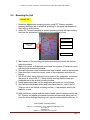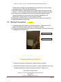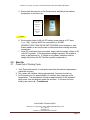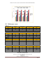
1
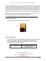
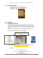
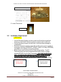
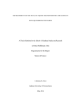
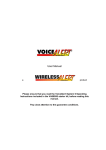
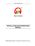
DC8600T / DC11000T / DC17000T / DC22000T INSTALLATION AND OPERATION MANUAL DC TELECOM ® SERIES SELF-CONTAINED, CLOSED LOOP 48 VOLT DC AIR CONDITIONER DC8600T | DC11000T |DC17000T|DC22000T INSTALLATION & OPERATION MANUAL Raytheon Picture SUN POWER TECHNOLOGIES 17406 Tiller Court; Westfield, IN 46074| WWW.SUNPOWERTECH.COM DCT – REV1.5 JANUARY 2014 SUBJECT TO CHANGE WITHOUT NOTICE Page 1 DC8600T / DC11000T / DC17000T / DC22000T INSTALLATION AND OPERATION MANUAL How To Use This Manual This manual is intended to be a guide to Sun Power Technologies line of vertical air conditioners. It contains installation, troubleshooting, maintenance, warranty, and application information. The information contained in this manual is to be used by the installer as a guide only. This manual does not supersede or circumvent any applicable national or local codes. If you are installing the DC Telecom Series unit, first read Chapter 1 and scan the entire manual before beginning the installation as described in Chapter 2. Chapter 1 contains general, descriptive information and provides an overview which can speed up the installation process and simplify troubleshooting. If a malfunction occurs, follow this troubleshooting sequence: 1. Make sure you understand how the DC Telecom Series unit works (Chapters 1 & 3). 2. Identify and correct installation errors (Chapter 2). 3. Refer to the troubleshooting information in Chapter 4. If you are still unable to correct the problem, contact the Factory at 317-399-8113 for additional assistance. Please read the following “Important Safety Precautions” before beginning any work. Important Safety Precautions 1. USE CARE when LIFTING or TRANSPORTING equipment. 2. TRANSPORT the UNIT UPRIGHT. Laying it down on its side may cause oil to leave the compressor and breakage or damage to other components. If unit has been transported laying down, it must be positioned upright for at least 1 hour prior to unit being powered ON. 3. TURN ELECTRICAL POWER OFF AT THE breaker or fuse box BEFORE installing or working on the equipment. LINE VOLTAGES ARE HAZARDOUS or LETHAL. 4. OBSERVE and COMPLY with ALL applicable PLUMBING, ELECTRICAL, and BUILDING CODES and ordinances. 5. SERVICE may be performed ONLY by QUALIFIED and EXPERIENCED PERSONS. o Wear safety goggles when servicing the refrigeration circuit o Beware of hot surfaces on refrigerant circuit components o Beware of sharp edges on sheet metal components o Use care when recovering or adding refrigerant 6. Use COMMON SENSE - BE SAFETY-CONSCIOUS This is the safety alert symbol . When you see this symbol on the DC Telecom ® unit and in the instruction manuals be alert to the potential for personal injury. Understand the signal word DANGER, WARNING and CAUTION. These words are used to identify levels of the seriousness of the hazard. Failure to comply will result in death or severe personal injury and/or property damage. DANGER WARNING Failure to comply could result in death or severe personal injury and/or property damage. CAUTION Failure to comply could result in minor personal injury and/or property damage. IMPORTANT SUN POWER TECHNOLOGIES 17406 Tiller Court; Westfield, IN 46074| WWW.SUNPOWERTECH.COM DCT – REV1.5 JANUARY 2014 SUBJECT TO CHANGE WITHOUT NOTICE Page 2 DC8600T / DC11000T / DC17000T / DC22000T INSTALLATION AND OPERATION MANUAL Is used to point out helpful suggestions that will result in improved installation, reliability or operation DANGER If the information in these instructions is not followed exactly, a fire may result causing property damage, personal injury or loss of life. Read all instructions carefully prior to beginning the installation. Do not begin installation if you do not understand any of the instructions. Improper installation, adjustment, alteration, service or maintenance can cause property damage, personal injury or loss of life. Installation and service must be performed by a qualified installer or service agency in accordance with these instructions and in compliance with all codes and requirements of authorities having jurisdiction. INSTALLER: Affix the instructions on the inside of the building adjacent to the thermostat. END USER: Retain these instructions for future reference. SUN POWER TECHNOLOGIES 17406 Tiller Court; Westfield, IN 46074| WWW.SUNPOWERTECH.COM DCT – REV1.5 JANUARY 2014 SUBJECT TO CHANGE WITHOUT NOTICE Page 3 DC8600T / DC11000T / DC17000T / DC22000T INSTALLATION AND OPERATION MANUAL Table of Contents Chapter 1 DC TELECOM ® Series A/C Description & Specifications 1.1 General Description 1.3 Serial Number 1.4 Air Flow and Filter 1.5 General Operation 1.6 Electronic Control Board 1.7 Optional Controls 1.8 Electrical Diagrams Chapter 2 Installation 2.1 Equipment Inspection 2.2 Installation Requirements 2.3 Installation Tools and Materials 2.4 Mounting the Unit 2.5 Electrical Connections Chapter 3 Start-Up 3.1 Check-Out of Cooling Cycle 3.2 Check-Out of Heating Cycle (OPTIONAL) Chapter 4 Troubleshooting WARNIN Chapter 5 Maintenance Chapter 6 Performance Data Chapter 7 Warranty 7.1 Procedures and Forms 1.1 General Description Sun Power Technologies DC Telecom® series of vertical wall-mounted air conditioning systems provide high efficiency, DC powered cooling, and heating (optional) for electronic equipment shelters, process control centers, and other applications with high internal heat gains. The series includes multiple sizes and nominal cooling capacities from 8,600 to 22,000 BTUH. SUN POWER TECHNOLOGIES 17406 Tiller Court; Westfield, IN 46074| WWW.SUNPOWERTECH.COM DCT – REV1.5 JANUARY 2014 SUBJECT TO CHANGE WITHOUT NOTICE Page 4 DC8600T / DC11000T / DC17000T / DC22000T INSTALLATION AND OPERATION MANUAL Sun Power Technologies DC Telecom® series air conditioners feature a proprietary DC compressor/controller combination that operates on true DC power. The systems have a smart control board that consolidates several of the electrical components, monitors battery state of charge and improves the air conditioner’s reliability. The control board has an integrated blower relay, lockout relay, compressor time delay and the timed low pressure bypass. In addition, the control board has a high/low voltage protection circuit. All DC Telecom® series models are designed for easy installation and service. Major components are accessible for service beneath external panels. ALL UNITS REQUIRE CIRCUIT PROTECTION AND VOLTAGE REGULATION. 1.3 Serial Number Label The Serial Number Label is located inside the enclosure. 1.4 Air Flow and Filters The DC TELECOM Series is equipped with a washable filter on the return air circuit. The system is designed to produce the following air flow using this filter. If alternative filter media is needed, please contact Sun Power Technologies to ensure adequate air flow can be maintained. Condenser Fan 360 CFM Evaporator Blower 580 (DC8600/11000/17000) 700 CFM (DC22000T) SUN POWER TECHNOLOGIES 17406 Tiller Court; Westfield, IN 46074| WWW.SUNPOWERTECH.COM DCT – REV1.5 JANUARY 2014 SUBJECT TO CHANGE WITHOUT NOTICE Page 5 DC8600T / DC11000T / DC17000T / DC22000T INSTALLATION AND OPERATION MANUAL Washable Filter 1.5 General Operation The DC TELECOM system is designed to provide climate control for your enclosure. The system is controlled by setting the mechanical thermostat at the desired temperature. Once the desired temperature has been set, the DC TELECOM series air conditioner will cycle to maintain the temperature setting. The system thermostat detects the set point and calls for cooling to be turned on or off when the temperature reaches +/- 3 degrees F delta from set point. The DC TELECOM Series system is equipped with a low voltage disconnect (LVD) to protect the battery source from over discharge. The LVD is designed to disconnect power from the air conditioner when voltage reaches 43 VDC and will automatically reset when input voltage reaches 51 VDC. 1.6 Electronic Control Board The DC TELECOM series system has an integrated control board that manages power flow for the system. The control board has 3 low current outputs that can be used to send alarm signals for compressor failure, low power and pressure failure. Please refer to wiring diagram 4.4 for details. 1.7 Optional Controls Sun Power Technologies offers the following control options: o Optional Digital Thermostat o Digital Lead Lag o Pre-set Temperature set point SUN POWER TECHNOLOGIES 17406 Tiller Court; Westfield, IN 46074| WWW.SUNPOWERTECH.COM DCT – REV1.5 JANUARY 2014 SUBJECT TO CHANGE WITHOUT NOTICE Page 6 DC8600T / DC11000T / DC17000T / DC22000T INSTALLATION AND OPERATION MANUAL 1.8 Electrical Diagrams o Electronic Controls – See Service Manual o Compressor Controller – See Service Manual o Wiring to Unit – See Service Manual 2.0 2.1 Installation Equipment Inspection 1.Open box that DC Telecom system is packaged in. Check all sheet metal and visible components for damage that may have occurred in transit. Please notify Sun Power Technologies immediately if damage is found. 2. Remove staples and/or tape from box and fold sides of box down. 3. Remove air conditioner from box and set upright Unit must be supported at base by packaging. If unit is placed directly on the ground, the condensate drain WILL be damaged CONTENTS (1) (1) (1) (1) (1) (1) DC Telecom AC unit Mounting hardware kit (6) 13mm bolts (6) Flat washers (6) Lock washers (1) Plastic anti chafe ring (1) Condensation drain tube Grill Cover Plate w/ filter Mounting Template Thermostat w/ ring terminals (2) Installation and Operation Manual 4. Open component box and locate installation template and mounting THERMOSTAT ADDENDUM - REPLACES PAGES 9 & 13 THERMOSTAT ADDENDUM - REPLACES PAGES 9 & 13 Hardware SUN POWER TECHNOLOGIES 17406 Tiller Court; Westfield, IN 46074| WWW.SUNPOWERTECH.COM DCT – REV1.5 JANUARY 2014 SUBJECT TO CHANGE WITHOUT NOTICE Page 7 DC8600T / DC11000T / DC17000T / DC22000T INSTALLATION AND OPERATION MANUAL Full Size Template located in component bag 5. Locate Thermostat Thermostat Box 2.2 Installation Requirement IMPORTANT o Vertical Mounting Surface must be smooth and flat without significant texture in order for DC Telecom system to properly seal to structure o Vertical Mounting Surface must be level to ensure proper drainage of condensation o Structure must have a battery based 48 volt DC power source capable of managing a 40 Amp (DC8600/DC11000/DC17000) or 50 Amp (DC22000) load within 15’ (3 meters) of mounting location o Battery bank must be protected from high voltage spikes. The DC Telecom system has a pre-programmed shutdown mode if voltage exceeds 60 VDC for more than 5 seconds – VOLTAGE OVER 60VDC WILL CAUSE BOARD DAMAGE OR FAILURE. OVER VOLTAGE FAILURES WILL NOT BE COVERED UNDER WARRANTY o Vertical Mounting Surface must be able to support 150 pounds (70 Kg) UNACCEPTABLE Acceptable Structure / Vertical Mounting Surface Structure / Vertical Mounting Surface SUN POWER TECHNOLOGIES 17406 Tiller Court; Westfield, IN 46074| WWW.SUNPOWERTECH.COM DCT – REV1.5 JANUARY 2014 SUBJECT TO CHANGE WITHOUT NOTICE Page 8 DC8600T / DC11000T / DC17000T / DC22000T INSTALLATION AND OPERATION MANUAL 2.3 Installation Tools and Materials Tools o Reciprocating Saw or any saw capable of cutting template holes in structure vertical mounting surface o Power Drill o ½” (13mm) Drill bit with adequate length to drill through vertical mounting surface o ¾” (19mm) wrench or socket o 5/16” (8mm) nut driver or socket o Flat blade screwdriver o Phillips head screwdriver o Measuring device o Bubble Level o Thermometer Materials o Adhesive Tape to secure template to vertical mounting surface o Silicone sealant – 1 tube o (2) ring terminals of appropriate size for 10 gauge power input cable to battery/power source Material Supplied (6) ½”x6” (13mm x 155mm) mounting bolts (6) flat washers (6) lock washers Weather stripping gasket – attached to system Anti-chafe ring for wiring harness Power input wiring – 15’ (5 meters) red and black 10/8 gauge – attached to system o Thermostat wiring – 15’ (5 meters) attached to system o Washable filter o o o o o o SUN POWER TECHNOLOGIES 17406 Tiller Court; Westfield, IN 46074| WWW.SUNPOWERTECH.COM DCT – REV1.5 JANUARY 2014 SUBJECT TO CHANGE WITHOUT NOTICE Page 9 DC8600T / DC11000T / DC17000T / DC22000T INSTALLATION AND OPERATION MANUAL 2.4 Mounting the Unit IMPORTANT 1. Determine appropriate mounting location using DC Telecom template, ensuring that there are no electrical, plumbing or structural interferences in the cutout or drilling areas 2. Attach DC Telecom template to vertical mounting surface with tape making sure that the vertical line (either side) on the template is level Evaporator Cutout Wiring Hole Mounting Bolt Holes (6) Return Air Cutout Level Line 3. Mark centers of the mounting bolt holes and wiring holes onto the vertical mounting surface 4. Mark four corners of Evaporator cutout and four corners of Return air cutout onto the vertical mounting surface. 5. Once all holes and corner locations have been marked, remove the template. 6. Draw lines that connect the corner marks of the evaporator and return air cutouts 7. Drill 6 bolt holes, wiring hole and corner marks of the evaporator cutout and the return air cutout with ¾” (19mm) drill bit ensuring that the holes are perpendicular to the vertical mounting surface 8. Using reciprocating saw, cut the evaporator and return air cutout marks 9. Once all holes have been drilled and holes have been cut, test fit the DC Telecom unit to the vertical mounting surface – if adjustments need to be made do so now. 10. With one person outside and one person inside, person outside position the DC Telecom unit against the vertical mounting surface while taking care to route the wiring through the wiring hole– person inside attach bottom two ½” SUN POWER TECHNOLOGIES 17406 Tiller Court; Westfield, IN 46074| WWW.SUNPOWERTECH.COM DCT – REV1.5 JANUARY 2014 SUBJECT TO CHANGE WITHOUT NOTICE Page 10 DC8600T / DC11000T / DC17000T / DC22000T INSTALLATION AND OPERATION MANUAL (13mm) bolts using flat and lock washers to secure the unit to the vertical mounting surface. Bolts should be hand tight. 11. Once unit is secure, attach the grill cover inside of the structure to the unit using 4- ½” (13mm) bolts, flat and lock washers. Bolts should be hand tight. 12. Once all bolts are installed and the wiring is pulled through the vertical mounting surface into the structure, bolts should be tightened to 40 foot/pounds – taking care to not over tighten the bolts. 13. Place plastic grommet around wiring and snap into grill cover wiring hole 14. Install filter element to grill cover 2.5 Electrical Connections DANGER 1. Locate the power input cables in the wiring harness. The wires are 10/8 gauge red and black copper strand 15’ (5 meters) in length 2. Locate the thermostat connection cable in the harness. The thermostat input is wrapped in black wire loom. 48 Volt DC Power Input Thermostat Connection THERMOSTAT ADDENDUM - REPLACES PAGES 9 & 13 3. Attach wire harness to thermostat. Adjust length as needed. 4. Attach thermostat to electric junction box on interior wall away from direct sunlight and away from direct air flow from the DC Telecom unit SUN POWER TECHNOLOGIES 17406 Tiller Court; Westfield, IN 46074| WWW.SUNPOWERTECH.COM DCT – REV1.5 JANUARY 2014 SUBJECT TO CHANGE WITHOUT NOTICE Page 11 DC8600T / DC11000T / DC17000T / DC22000T INSTALLATION AND OPERATION MANUAL 5. Ensure that the set point on the thermostat is well above the ambient temperature in the structure Attach Black wire to terminal on left and Blue wire to terminal on right DANGER 6. Route power cables to 48 volt DC battery power source or DC buss (+ or – OK). System MUST be connected to a 40 AMP (DC8600/11000/17000) OR 50 AMP (DC22000) circuit breaker or fuse. Please adhere to any local codes or restrictions when making electrical connections. 7. Once DC power has been connected, ensure that the supply voltage is 48 volts DC or greater. If the appropriate voltage is present, the system is ready to be powered on. If voltage is not present, batteries must be charge fully before the DC Telecom system is powered on. 3.0 3.1 Start Up Check out of Cooling Cycle 1. Turn Thermostat control to a set point lower than the ambient temperature Inside the structure. 2. The system will initialize, taking approximately 3 minutes for start-up. 3. Let the system run for approximately 15 minutes, then check the outlet temperature. The temperature should be approximately 20-30 degrees F delta cooler from the ambient inside the structure. If unit does not cool initially, see section 4 – Troubleshoot SUN POWER TECHNOLOGIES 17406 Tiller Court; Westfield, IN 46074| WWW.SUNPOWERTECH.COM DCT – REV1.5 JANUARY 2014 SUBJECT TO CHANGE WITHOUT NOTICE Page 12 DC8600T / DC11000T / DC17000T / DC22000T INSTALLATION AND OPERATION MANUAL 4.0 Troubleshooting See Attached Troubleshoot and Maintenance Manual 5.0 Maintenance 5.1 Scheduled Maintenance Sun Power Technologies strongly recommends that the air conditioner be serviced a minimum of twice a year – once prior to the heating season and once prior to the cooling season. At this time the filters, evaporator coil, condenser coil, the cabinet, and condensate drains should be serviced as described below. Also at this time, the air conditioner should be operated in the cooling and heating cycles as described in Chapter 3, Start-Up. In addition to this seasonal check-out, the DC Telecom System should be maintained as follows: Air Filter Replace / Clean the air filter whenever it is visibly dirty. Evaporator If the evaporator becomes clogged or dirty, it may be cleaned by careful vacuuming or with a commercial evaporator cleaning spray. DO NOT use a solvent containing bleach, acetone, or flammable substances. Turn off power before cleaning. Be careful not to wet any of the electrical components. Be sure the unit has dried before restarting. Condenser Periodically inspect the outdoor condenser coil and the cabinet air reliefs for dirt or obstructions. Remove foreign objects such as leaves, paper, etc. If the condenser coil is dirty, it may be washed off with a commercial solvent intended for this purpose. TURN OFF POWER BEFORE CLEANING! Be sure that all electrical components are thoroughly dry before restoring power. Cabinet The cabinet may be cleaned with a sponge and warm, soapy water or a mild detergent. Do not use bleach, abrasive chemicals or harmful solvents. Drains Regularly check the condensate drains. The drain has a stand pipe. An obstruction will force water to dump into the middle of the unit and drain out the SUN POWER TECHNOLOGIES 17406 Tiller Court; Westfield, IN 46074| WWW.SUNPOWERTECH.COM DCT – REV1.5 JANUARY 2014 SUBJECT TO CHANGE WITHOUT NOTICE Page 13 DC8600T / DC11000T / DC17000T / DC22000T INSTALLATION AND OPERATION MANUAL sides of the DC Telecom System, causing discoloration of the side panels. If discoloration is noted, service the drain. If a commercial drain solvent is used, flush out the drain pan and system with plenty of fresh water to prevent corrosion. Lubrication Oiling of the condenser fan motor or the evaporator blower motor is not recommended. SUN POWER TECHNOLOGIES 17406 Tiller Court; Westfield, IN 46074| WWW.SUNPOWERTECH.COM DCT – REV1.5 JANUARY 2014 SUBJECT TO CHANGE WITHOUT NOTICE Page 14 DC8600T / DC11000T / DC17000T / DC22000T INSTALLATION AND OPERATION MANUAL 6.0 Performance Tables DC8600T - 48 Nominal Input Voltage Duty Cycle % 100 100 100 100 100 Relative Humidity % 80 80 80 80 80 Ambient Air Temperature C 35 40 45 50 55 Power Consumption Watts 685 692 714 746 821 Duty Cycle % 100 100 100 100 100 Relative Humidity % 80 80 80 80 80 Ambient Air Temperature C 35 40 45 50 55 Power Consumption Watts 819 836 844 878 966 48 VDC 48 VDC 48 VDC 48 VDC Duty Cycle % 100 100 100 100 Relative Humidity % 80 80 80 80 Ambient Air Temperature C 35 40 45 50 Power Consumption Watts 1270 1284 1305 1397 48 VDC 100 80 55 1437 48 VDC 48 VDC 48 VDC 48 VDC Duty Cycle % 100 100 100 100 Relative Humidity % 80 80 80 80 Ambient Air Temperature C 35 40 45 50 Power Consumption Watts 1930 1977 2000 2028 48 VDC 100 80 55 2080 48 VDC 48 VDC 48 VDC 48 VDC 48 VDC DC11000T – 48 Nominal Input Voltage 48 VDC 48 VDC 48 VDC 48 VDC 48 VDC DC17000T – 48 Nominal Input Voltage DC22000 -48 Nominal Input Voltage SUN POWER TECHNOLOGIES 17406 Tiller Court; Westfield, IN 46074| WWW.SUNPOWERTECH.COM DCT – REV1.5 JANUARY 2014 SUBJECT TO CHANGE WITHOUT NOTICE Page 15 DC8600T / DC11000T / DC17000T / DC22000T INSTALLATION AND OPERATION MANUAL 7.0 Warranty LIMITED WARRANTY Sun Power Technologies, LLC (SPT) warrants its products to be free from defects in materials and workmanship for a 12 month period from the date of installation by end user or authorized distributor. SPT’s obligation under this warranty is limited to repairing or replacing (at its sole option) any such defective products. To obtain service under this warranty you must obtain a Returned Material Authorization (RMA) number from SPT or an authorized SPT service center. Products must be returned to SPT or an authorized SPT service center with transportation prepaid and must be accompanied by a brief description of the problem encountered and proof of date and place of purchase. This warranty does not apply to equipment which has been damaged by accident, negligence or misapplication or has been altered or modified in any way, including opening of the unit’s casing for any reason. This warranty applies only to the original purchaser who must have PROPERLY REGISTERED the product within 10 days of retail purchase or installation. EXCEPT AS PROVIDED HEREIN, SUN POWER TECHNOLOGIES, LLC MAKES NO WARRANTIES, EXPRESS OR IMPLIED, INCLUDING WARRANTIES OF MERCHANTABILITY AND FITNESS FOR A PARTICULAR PURPOSE. Some states do not permit limitation or exclusion of implied warranties; therefore, the aforesaid limitation (s) or exclusion (s) may not apply to the purchaser. EXCEPT AS PROVIDED ABOVE, IN NO EVENT WILL SUN POWER TECHNOLOGIES, LLC BE LIABLE FOR DIRECT, INDIRECT, SPECIAL, INCIDENTAL OR CONSEQUENTIAL DAMAGES ARISING OUT OF THE USE OF THIS PRODUCT, EVEN IF ADVISED OF THE POSSIBILITY OF SUCH DAMAGE. Specifically, SPT is not liable for any costs, such as lost profits or revenue, loss of equipment, loss of use of equipment, loss of software, loss of data, cost of substitutes, claims by third parties, or otherwise. Sun Power Technologies, LLC has a policy of continuous improvement. Specifications are subject to change without notice. Products covered by this warranty**: DC Air Conditioners: DC3600, DC5000, DC1500T, DC6000/6000T DC8600/8600T, DC11000/11000T, DC17000/17000T, DC22000/ DC22000T, DC5000M, Hybrid Air Conditioners 7.1 Warranty Procedures and Forms Included in packaging SUN POWER TECHNOLOGIES 17406 Tiller Court; Westfield, IN 46074| WWW.SUNPOWERTECH.COM DCT – REV1.5 JANUARY 2014 SUBJECT TO CHANGE WITHOUT NOTICE Page 16