1
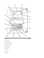
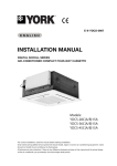
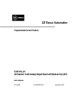
Operation and Maintenance Manual
784C and 785C Off-Highway Truck/Tractor
Vital Information Management System (VIMS) Keypad
Illustration 1
(1) Alert indicator
(2) Message center module
(3) Data logging indicator
(4) Gauge warning area
(5) Universal gauge
(6) Message area
(7) "F1" key
(8) "F3" key
(9) "ID" key
g01177548
(10) "F2" key
(11) Forward key
(12) Backward key
(13) "GAUGE" key
(14) "OK" key
(15) Indicator light
(16) Keypad
The Vital Information Management System (VIMS) uses keypad (16) to allow the operator to request
information. The keypad controls the display of text in message area (6) .
Indicator light (1) will flash whenever a key is pressed. The indicator light informs the operator that
the command has been accepted.
Some information can be requested by using the numbers on the keypad . The series of numbers is
called a Service Program Code. The letters that are associated with the numbers describe the
requested operation of the Service Program Codes.
Note: After entering the Service Program Code on the keypad, the code must be completed by
pressing "OK" key (14) .
The following table contains the Service Program Codes that are needed by the operator. Refer to
Service Manual, RENR2630 and RENR2631, "785 - 797 Off-Highway Trucks Vital Information
Management System" for additional Service Program Codes.
Table 1
Service Program Codes
Numbers
Letters
Description
52
LA
Change the Language.
86
UN
Metric Units or English Units
868
TOT
View the Cumulative Data.
73738
RESET
Reset the Cumulative Data.
3564
DLOG
Log the Data or Stop Logging the Data.
8378
TEST
Test of the VIMS
258
BLT
Backlighting Intensity of the Message Area
266
CON
Contrast of the Message Center
LA - Entering 52 causes the text in the message area to toggle between two languages.
UN - Entering 86 toggles between Metric units and English units.
TOT - Entering 868 shows the total number of loads, the total payload, the total travel distance, and
the total travel time. This data is called the cumulative data. The cumulative data can be reset. The
totals since the last reset will be listed. Scroll through the list with Forward key (11) and with
Backward key (12) .
RESET - Entering 73738 clears the cumulative data.
DLOG - Entering 3564 will cause the VIMS to start logging data. If the VIMS is already logging
data, entering 3564 will cause the VIMS to stop logging data. Data logging indicator (3) will be ON
when the VIMS is logging data. The data from all of the parameters will be recorded. The data is
stored in a file and the file can be downloaded by using the VIMS-PC software for analysis of the
machine systems.
TEST - Entering 8378 will run the self test of the VIMS. Refer to Operation And Maintenance
Manual, "Vital Information Management System (VIMS)" for additional information about the self
test of the VIMS.
BLT - Entering 258 will cause the intensity of the message area to begin scrolling by 5 percent
increments. The corresponding percentage of the intensity is displayed in the message area. Use
Backward key (12) and Forward key (11) in order to select the desired intensity. Press "OK" key (8)
in order to accept the new selection.
CON - Entering 266 will cause the contrast of the message area to begin scrolling by 5 percent
increments. The corresponding percentage of the contrast is displayed in the message area. Use
Backward key (12) and Forward key (11) in order to select the desired intensity. Press "OK" key (14)
in order to accept the new selection.
Keys
"OK" Key
"OK" key (14) is used in order to indicate that entries are complete. This key is also used in order to
acknowledge all events.
"F1" Key
"F1" key (7) is used by the operator in order to request additional information about a data event.
There are two types of events. Data events warn the operator that the value of a monitored parameter
is not in the specified range. Maintenance events warn the operator about electrical problems.
When a data event is displayed in message area (6) , pressing the "F1" key will show the actual data
about the condition. For example, if the condition is high temperature, pressing the "F1" key will
show the value of the temperature.
When a maintenance event is displayed in the message area, pressing the "F1" key will display the
diagnostic code information. See Service Manual, RENR2630 and RENR2631, "785 - 797 OffHighway Trucks Vital Information Management System" and Special Instruction, REHS0126,
"Caterpillar Electronic Control Codes"for a complete list of MID values, of CID values and of FMI
values.
Note: The switches do not have any CID or FMI diagnostic information. The message area will show
the state of the switch. Some examples of information that will be shown on the message area are
"CLOSED", "OPEN", "NEUTRAL" and "UP".
Forward Key and Backward Key
Backward key (12) and Forward key (11) allow scrolling forward or backward in order to display
rows of text in message area (6) .
"GAUGE" Key
"GAUGE" key (13) is used to determine the measured value of a particular parameter. The value will
be shown in message area (6) . The value will also be shown on universal gauge (5) in message center
module (2) .
When the "GAUGE" key is pressed, the following information is shown in the message center
module:
• The name of the parameter and the ID of the parameter are displayed in the first row of text.
• The value of the parameter and the corresponding units are displayed in the second row of text.
• The universal gauge displays the value on an analog gauge.
This information is shown for one parameter at a time. Use the Forward key and the Backward key to
scroll through the available parameters.
Each parameter has an identification number so that specific information can be requested. To view
specific parameter information, enter the identification number. Then press the "GAUGE" key.
Parameter information remains on the message center until "OK" key (14) is pressed. Default data
(time of day and service meter hours) is then shown.
The following items are the available parameters and the corresponding identification numbers of the
parameters:
Note: The parameters that are available on individual machines may differ slightly.
Table 2
Parameter Information of the VIMS
Name of the Parameter
Identification Number of the Parameter
Eng Spd
100
Lt Trbo In Pres
102
Rt Trbo In Pres
103
Air Fltr
104
Boost Pres
105
Lt Exh Temp
106
Rt-Lt Exh Temp
107
Rt Exh Temp
108
F Aftclr Temp
111
R Aftclr Temp
112
Wastegate Pos
114
Cool Fan Spd
115
Cold Mode
116
Eng Derate
117
Air Fltr
118
Eng Load
121
Fuel Fltr
122
Fuel Lvl
123
Throttl Pos
125
Eng Fuel Rate
129
Eng Oil Lvl
130
Eng Oil Pres
131
Cnkcase Pres
133
Eng Cool Flow
134
Eng Cool Temp
135
Aftclr Lvl
137
Eng Cool Lvl
138
Sys Voltage
140
Hi Boost Pres
145
Lo Boost Pres
146
Cnkcase Pres
147
Total Fuel
187
Eng Fan Spd #1
197
Eng Fan Spd #2
198
Rt-Lt Fan Spd
199
Eng Fan Temp
200
RAX Dvrt Sol St
229
TC Filter
310
TC Out Spd
311
TC Screen
312
TC Out Temp
313
Diff Temp
325
Diff Fltr Sw
327
Diff Lube Pres
328
Trn Lockout St
340
Trn Gear
349
Trn Lube Temp
350
Gear Select
351
Actual Gear
352
Trn Out Spd
355
Trn Chrg Fltr
356
Trn Lube Fltr
357
Trn Slip
358
Lckup Slip
359
Brk Pump Spd
377
Retarder
380
Brk Lockdn
382
Lt R Wheel Spd
418
Rt R Wheel Spd
419
Mach Lock Sw
432
RtR-RtF BrkTemp
436
LtR-LtF BrkTemp
437
Strg Pmp Pres
440
Lo Strg Pres
441
Hi Strg Pres
442
Strg Oil Temp
444
Brk/Air Pres
452
ParkBrk
453
Brk Fltr
454
Brk Stroke
456
Lt F Brk Temp
460
Lt R Brk Temp
461
Rt F Brk Temp
462
Rt R Brk Temp
463
RtF-Ltf Brk Temp
464
RtR-LtR Brk Temp
465
ParkBk FltrSw
466
Eng Oil Fltr
485
ParkBk Fltr Sw
493
Hoist Screen
505
Diff Oil Lvl
513
Eng Fan Spd
520
RtF-LtF Susp Cyl
710
RtR-LtR Susp Cyl
711
Lt F Susp Cyl
720
Lt R Susp Cyl
721
Rt F Susp Cyl
722
Rt R Susp Cyl
723
Body Angle
724
Ground Spd
725
Body Pos
726
Body Lvr
727
Payload
728
Payload Status
729
Haul Distance
730
User Shutdown
742
Auto Lube
751
Atmos Pres
790
Amb Air Temp
791
Machine Pitch
792
Machine Rack
793
Hoist Lvr Pos
798
Hoist Status
799
VIMS Event List
800
Payload Data
801
VIMS Snapshot
802
Diff Pres Lo
812
Max Bias/Sec
849
Max Pitch/Sec
850
Max Rack/Sec
851
Cycle P Fela
852
Manual Erec
860
Cycle R Fela
862
Fela Trigger
869
Lo Oil Pres
907
Tkph F Tires
983
Tkph R Tires
984
Tkph F Warn
986
Tkph R Warn
987
Trn Oil Lvl
1022
Retatder Mode
1023
If an event occurs, the message area will display information about the event. After the problem is
corrected, the display in the message area will revert to the former display. Events will always
override parameter values.
"ID" Key
"ID" key (9) is used to enter the operator's identification number.
If this is required, this identification number should be entered at the beginning of an operator's shift.
When the "ID" key is pressed, a prompt for "ENTER ID" will be shown on the first row of text in the
message area. The operator may enter an ID number up to seven digits long on the second row.
If "OK" key (14) is not pressed within five seconds after the last number is entered, the identification
number will not be recorded. Then, the display will return to the previous condition.
If the "ID" key is pressed during the entry, the current entry will be cancelled and the process will
start again. This is helpful if a mistake is made during the entry. Backward key (23) will delete the
last number of the entry.
"F2" Key and "F3" Key
"F2" key (10) and "F3" key (8) are not currently used in this application.