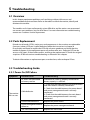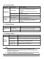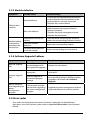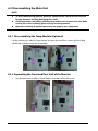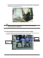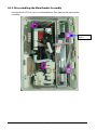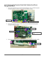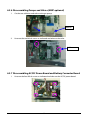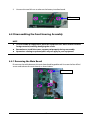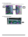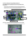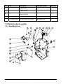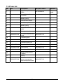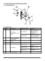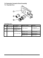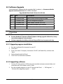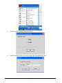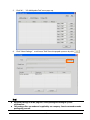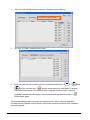
1
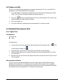
VS-600 Vital Signs Monitor Service Manual Intellectual Property Statement SHENZHEN MINDRAY BIO-MEDICAL ELECTRONICS CO., LTD. (hereinafter called Mindray) owns the intellectual property rights to this product and this manual. This manual may refer to information protected by copyrights or patents and does not convey any license under the patent rights of Mindray, nor the rights of others. Mindray does not assume any liability arising out of any infringements of patents or other rights of third parties. , , and are the registered trademarks or trademarks owned by Mindray in China and other countries. Revision History This manual has a revision number. This revision number changes whenever the manual is updated due to software or technical specification change. Contents of this manual are subject to change without prior notice. The version information of this manual is as follows: Version number: 1.0 Release time: May 2013 © Copyright 2013 Shenzhen Mindray Bio-Medical Electronics Co., Ltd. All rights reserved. I Preface Manual Purpose This manual provides detailed information about the assembling, dissembling, testing and troubleshooting of the equipment to support effective troubleshooting and repair. It is not intended to be a comprehensive, in-depth explanation of the product architecture or technical implementation. This manual is based on the maximum configuration and therefore some contents may not apply to your product. If you have any question, please contact our Customer Service Department. Observance of the manual is a prerequisite for proper equipment maintenance and prevents equipment damage and personnel injury. Intended Audience This manual is for biomedical engineers, authorized technicians or service representatives responsible for troubleshooting, repairing and maintaining the equipment. II Contents 1 Introduction........................................................................................................................... 1-1 1.1 Information of This Manual......................................................................................................................1-1 1.2 Safety Information.......................................................................................................................................1-1 1.2.1 Dangers..............................................................................................................................................1-1 1.2.2 Warnings............................................................................................................................................1-2 1.2.3 Cautions.............................................................................................................................................1-2 1.2.4 Notes ...................................................................................................................................................1-2 1.3 Equipment Symbols ...................................................................................................................................1-3 2 Theory of Operation .............................................................................................................. 2-1 2.1 Overview.........................................................................................................................................................2-1 2.2 Connectors for Peripheral Devices........................................................................................................2-1 2.3 Main Unit ........................................................................................................................................................2-2 2.4 Front Housing Assembly...........................................................................................................................2-3 2.5 Rear Housing Assembly ............................................................................................................................2-4 2.6 External Module...........................................................................................................................................2-5 3 Equipment Installation ......................................................................................................... 3-1 3.1 Unpacking the Equipment.......................................................................................................................3-1 3.2 Preparation for Installation ......................................................................................................................3-1 3.2.1 Preparation for Installation Site ................................................................................................3-1 3.2.2 Environmental Requirements....................................................................................................3-1 3.2.3 Electrical Requirements ...............................................................................................................3-2 3.3 Equipment Installation ..............................................................................................................................3-2 3.4 Preparation for Power on..........................................................................................................................3-3 4 Testing and Maintenance ...................................................................................................... 4-1 4.1 Introduction...................................................................................................................................................4-1 4.1.1 Test Equipment ...............................................................................................................................4-1 4.1.2 Test Report ........................................................................................................................................4-1 4.1.3 Preventative Maintenance..........................................................................................................4-1 4.1.4 Recommended Frequency .........................................................................................................4-2 4.2 Visual Inspection..........................................................................................................................................4-2 4.3 Power-on Test................................................................................................................................................4-3 4.4 Module Performance Tests.......................................................................................................................4-3 4.4.1 SpO2 Test............................................................................................................................................4-3 4.4.2 NIBP Test ............................................................................................................................................4-4 4.4.3 Temp Test...........................................................................................................................................4-8 4.5 Electric safety tests......................................................................................................................................4-8 1 4.6 Battery Check................................................................................................................................................ 4-8 4.7 Maintenance Mode..................................................................................................................................... 4-9 4.7.1 Entering/Quitting Maintenance Mode .................................................................................. 4-9 4.7.2 Checking Version Information................................................................................................... 4-9 4.7.3 Restoring Factory Default Configuration............................................................................4-10 5 Troubleshooting .................................................................................................................... 5-1 5.1 Overview......................................................................................................................................................... 5-1 5.2 Parts Replacement ...................................................................................................................................... 5-1 5.3 Troubleshooting Guide ............................................................................................................................. 5-1 5.3.1 Power On/Off Failure..................................................................................................................... 5-1 5.3.2 Display Failures ............................................................................................................................... 5-2 5.3.3 Button Failures ................................................................................................................................ 5-2 5.3.4 Battery Failures................................................................................................................................ 5-2 5.3.5 Module defective ........................................................................................................................... 5-3 5.3.6 Software Upgrade Problems...................................................................................................... 5-3 5.4 Error codes ..................................................................................................................................................... 5-3 6 Disassembly and Repair........................................................................................................ 6-1 6.1 Tools Required .............................................................................................................................................. 6-1 6.2 Preparations for Disassembly ................................................................................................................. 6-1 6.3 Disassembling the Main Unit.................................................................................................................. 6-2 6.3.1 Disassembling the Temp Module (Optional)....................................................................... 6-2 6.3.2 Separating the Front and Rear Half of the Monitor........................................................... 6-2 6.3.3 Removing the Parameter Connector Panel Assembly ..................................................... 6-3 6.3.4 Disassembling the Main Bracket Assembly ......................................................................... 6-4 6.3.5 Removing the Parameter Board (SpO2 Optional) and Power Management Board6-5 6.3.6 Disassembling Pumps and Valves (NIBP optional) ............................................................ 6-6 6.3.7 Disassembling AC/DC Power Board and Battery Converter Board ............................. 6-6 6.4 Disassembling the Front Housing Assembly .................................................................................... 6-7 6.4.1 Removing the Main Board.......................................................................................................... 6-7 6.4.2 Removing the Display .................................................................................................................. 6-8 6.4.3 Removing the Keypad.................................................................................................................. 6-8 6.5 Disassembling the Temp Module (Optional) .................................................................................... 6-9 6.5.1 Removing the Temp Module PCBA and Temp Module Power Board PCBA............. 6-9 6.5.2 Disassembling the Temp On-Position Detection Board PCBA...................................... 6-9 7 Parts........................................................................................................................................ 7-1 7.1 Introduction................................................................................................................................................... 7-1 7.2 Main Unit ........................................................................................................................................................ 7-1 7.2.1 Exploded View................................................................................................................................. 7-1 2 7.2.2 Parts List.............................................................................................................................................7-2 7.3 Front Housing Assembly...........................................................................................................................7-3 7.3.1 Exploded View .................................................................................................................................7-3 7.3.2 Parts List.............................................................................................................................................7-3 7.4 Main Bracket Assembly .............................................................................................................................7-4 7.4.1 Exploded View .................................................................................................................................7-4 7.4.2 Parts List.............................................................................................................................................7-5 7.5 Power Management Board Assembly .................................................................................................7-6 7.5.1 Exploded View .................................................................................................................................7-6 7.5.2 Parts List.............................................................................................................................................7-6 7.6 Parameter Connector Panel Assembly ................................................................................................7-7 7.6.1 Exploded View .................................................................................................................................7-7 7.6.2 Parts List.............................................................................................................................................7-7 7.7 Predictive Temp Assembly .......................................................................................................................7-8 7.7.1 Exploded View .................................................................................................................................7-8 7.7.2 Parts List.............................................................................................................................................7-8 8 Hardware and Software Upgrade......................................................................................... 8-1 8.1 Hardware Upgrade......................................................................................................................................8-1 8.1.1 Upgrade Package ...........................................................................................................................8-1 8.1.2 Upgrading Parameter Modules ................................................................................................8-1 8.1.3 Upgrading Temp.............................................................................................................................8-2 8.1.4 Enabling Parameter Functions ..................................................................................................8-2 8.2 Software Upgrade .......................................................................................................................................8-3 8.2.1 Upgrade program installation...................................................................................................8-3 8.2.2 Upgrading software ......................................................................................................................8-3 A Electrical Safety Inspection ..................................................................................................A-1 A.1 Power Cord Plug ........................................................................................................................................ A-1 A.2 Device Enclosure and Accessories ...................................................................................................... A-2 A.3 Device Labeling ......................................................................................................................................... A-2 A.4 Protective Earth Resistance ................................................................................................................... A-2 A.5 Earth Leakage Test .................................................................................................................................... A-4 A.6 Patient Leakage Current ......................................................................................................................... A-5 A.7 Mains on Applied Part Leakage ........................................................................................................... A-7 3 FOR YOUR NOTES 4 1 Introduction 1.1 Information of This Manual A detailed revision history of this manual is recorded in the table below: Version Revision History 1.0 New 1.2 Safety Information DANGER z Indicates an imminent hazard that, if not avoided, will result in death or serious injury. WARNING z Indicates a potential hazard or unsafe practice that, if not avoided, will result in death or serious injury. CAUTION z Indicates a potential hazard or unsafe practice that, if not avoided, could result in minor personal injury or product/property damage. NOTE z Provides application tips or other useful information to ensure that you get the most from your product. 1.2.1 Dangers There are no dangers that refer to the product in general. Specific “Danger” statements may be given in the respective sections of this manual. 1-1 1.2.2 Warnings WARNING z All installation operations, expansions, changes, modifications and repairs of this product are conducted by Mindray authorized personnel. z There is high voltage inside the equipment. Never disassemble the equipment before it is disconnected from the AC power source or the battery. z When you disassemble/reassemble a parameter module, a patient leakage current test must be performed before it is used again for monitoring. z The equipment must be connected to a properly installed power outlet with protective earth contacts only. If the installation does not provide for a protective earth conductor, disconnect it from the power line and operate it on battery power, if possible. z Disposal of the packaging material should observe the applicable waste control regulations and keeping it out of children’s reach. 1.2.3 Cautions CAUTION z Make sure that no electromagnetic radiation interferes with the performance of the equipment when preparing to carry out performance tests. Mobile phone, X-ray equipment or MRI devices are a possible source of interference as they may emit higher levels of electromagnetic radiation. z Before connecting the receiver to the power line, check that the voltage and frequency ratings of the power line are the same as those indicated on the unit’s label or in this manual. z Protect the equipment from damage caused by drop, impact, strong vibration or other mechanical force during servicing. 1.2.4 Notes NOTE z Refer to Operator's Manual for detailed operation and other information. 1-2 1.3 Equipment Symbols NOTE z Not all the symbols listed below are applied to your equipment. Caution: Consult accompanying documents(this manual) Neonate Power ON/OFF Pediatric Clear Adult Alternating current (AC) Equipotentiality Battery indicator Input/Output DEFIBRILLATION –PROOF TYPE CF APPLIED PART Date of manufacture NIBP Start/Stop key Manufacturer Serial number Insertion Direction No alarming system Protection against fluid ingress The following definition of the WEEE label applies to EU member states only. This symbol indicates that this product should not be treated as household waste. By ensuring that this product is disposed of correctly, you will help prevent bringing potential negative consequences to the environment and human health. For more detailed information with regard to returning and recycling this product, please consult the distributor from whom you purchased it. * For system products, this label may be attached to the main unit only. 1-3 2 Theory of Operation 2.1 Overview The monitor is intended for spot-check monitoring physiologic parameters, including SpO2, PR, NIBP and TEMP, on adult, pediatric, and neonatal patients in healthcare facilities by clinical physicians or appropriate medical staff under the direction of physicians. 2.2 Connectors for Peripheral Devices 1 2 3 1. Input/Output connect (RS-232 connector) This connector is used for software upgrade and DIAP communication. 2. AC power input 3. Equipotential grounding terminal: When the equipment and other devices are to be used together, their equipotential grounding terminals should be connected together to eliminate the potential difference between them. 2-1 2.3 Main Unit The main unit of the vital signs monitor consists of three parts: Front housing assembly, consisting of main board, segment-code display, and Power On/Off keypad; Rear housing assembly: power module (AC/DC), power management and interface board (including SpO2 isolation power), battery, NIBP module, and SpO2 board (including three types of configuration, i.e. Mindray, Masimo, and Nellcor); and, External module: Temp module. The following figure shows the main unit architecture of the vital signs monitor. Front Housing Assembly Segment-code display I2C Power On/Off keypad (indicator) Main board Backlight Rear Housing Assembly Pump Power management and interface board SpO2 isolation power 2600mAh battery NIBP receptacle NIBP module SpO2 board (Mindray standard, OEM optional) SpO2 receptacle External module Temp module 15V AC-DC power module AC-IN External connector Only RS232 port (for upgrade, screened for end users) 2-2 Temp probe 2.4 Front Housing Assembly Main Board Keypad Main Board The main board is the control center of the equipment. It provides communication and display functions, including: Communication with SpO2 board, and NIBP module through serial ports, starting parameter measurement, and reading measured results; Communication with Predictive/IR (Infrared Radiation) Temp module through serial ports; Communication with power management board through serial ports; Extending an RS232 serial port; Control over the Segment-code LCD display through I2C; Providing backlight drive for segment-code display; Recognition of keypad actions, and providing corresponding response; Control over the beeper through IO port; and, Providing 24 hour timing via the inner RTC. Keypad The keypad consists of elements like keypad and AC/Battery indicator etc. 2-3 2.5 Rear Housing Assembly Power management and interface board AC/DC power module SpO2 board Battery compartment NIBP module Rear housing assembly consists of power module (AC/DC), power management and interface board (including SpO2 isolation power), battery compartment, NIBP module, and SpO2 board (including three types of configuration, i.e. Mindray, Masimo, and Nellcor). AC/DC Power Module The AC/DC power board transforms the input AC into DC power, which is the power source for all voltages in the equipment. Power management and interface board The power management interface board mainly provides the following functions: Charge and discharge of battery and charge detection; DC/DC conversion: outputs 12V and 5V DC power; Control over power On/Off key and AC, BAT indicator; Communication transmission among parameter modules; 2-4 Providing isolation power for Mindray/OEM SpO2 module; and, Providing external connectors, and also filter and protection for these connectors. NIBP Module The NIBP module consists of blood pressure measurement board and pump and valve assembly, providing measurement acquisition of blood pressure data. The main functions of the NIBP module are: NIBP measurement; and, Data exchange with the main board through the serial ports. SpO2 board The independently developed Mindray SpO2 board provides SpO2 measurement as good as other boards but with smaller size and lower consumption. The power management and interface board is also compatible with Nellcor NELL-1 SpO2 board and Masimo MS-2013 SpO2 board. The SpO2 board collects SpO2 signals, processes SpO2 algorithm and sends measurement results to the main board. The power management interface board provides isolation power for it. 2.6 External Module An external Temp module can be extended on the monitor. The independently developed Mindray Temp module consists of an isolation power board, Temp measurement board, and probes. The Temp measurement board collects Temp signals, processes algorithm and sends measurement results to the main board. 2-5 FOR YOUR NOTES 2-6 3 Equipment Installation 3.1 Unpacking the Equipment Open the package and take out the packing list. Check that all the articles included in the packing list are available and the quantity and specification are correct. Make sure that: All the optional parts purchased by the customer shall also be checked. Notify the supplier if provided components are not correct as compared to the packing list. In case of damage during transportation, keep the packing material and notify the supplier immediately. Keep the packing material till new equipment is accepted. 3.2 Preparation for Installation 3.2.1 Preparation for Installation Site 1. Ensure that the site meets all safety, environmental and power requirements. 2. Check that required power sockets are available. 3. Check that a network connector is available if the equipment needs to be connected to network. 3.2.2 Environmental Requirements To avoid explosion hazard, do not use the equipment in the presence of flammable anesthetics, vapors or liquids. The environment where the equipment will be used should be reasonably free from vibration, dust and corrosive substances. If these conditions are not met, the system may not function normally. The environmental specification is as follows: Main Unit Item Temperature (℃) Relative humidity (noncondensing) Altitude (kPa) Operating environment 0 to 40 (without Temp module) 5 to 40 (with Temp module) 15% to 95% 57.0 to 107.4 Storage environment -30 to 70 10% to 95% 16.0 to 107.4 3-1 NOTE z The environmental specifications of unspecified parameters are the same as those of the main unit. 3.2.3 Electrical Requirements Check that the system cables, power cords, and power plugs are not damaged, and that the pins are not loose. In case of any damage, remove it from use. WARNING z Only power sockets with protective grounding can be used. z Use the supplied power cord only! z If you doubt the completeness of the installation and cabling of the external protective cables, disconnect the equipment from the power line and operate it on battery. Otherwise, patient or operator might be shocked. Voltage 100 to 240V AC Current 0.9 to 0.5A Frequency 50/60 Hz 3.3 Equipment Installation Follow the procedure below to install the equipment: 1. Check the quantity of equipment and accessories as per the packing list. 2. Check for mechanical damages on the equipment and accessories. 3. Install the battery (optional). For detailed operations, please refer to the Operator's Manual of the vital signs monitor. 4. Connect AC power. 5. Connect the accessories. The vital signs monitor can be mounted on a wall bracket or on a trolley support. The wall bracket or trolley support can be ordered optionally. Each type of mounting bracket is delivered with a complete set of mounting hardware and instructions. For detailed installation information, please refer to Wall-mount Bracket Instructions for Use (PN: 0010-20-42933) and Rollstand Instructions for Use (PN: 0010-20-42934). 3-2 CAUTION z Use mounting brackets we supply or approve. If other compatible mounting bracket is used, be sure it can be safely used on the vital signs monitor. z The mounting bracket should be installed by our qualified service personnel, or engineers who have adequate knowledge on it. z If other mounting solution is used, the installation personnel and the customer should verify if it can be safely used on the equipment, and the customer assume the responsibility for any risk resulting from that. 3.4 Preparation for Power on 1. Before you start to make measurements, check the equipment for any mechanical damage and make sure that all external cables, plug-ins and accessories are properly connected. 2. Plug the power cord into the AC power source. If you run the equipment on battery power, ensure that the battery is sufficiently charged. 3. Press the button on the front panel to turn on the equipment. 3-3 FOR YOUR NOTES 3-4 4 Testing and Maintenance 4.1 Introduction To ensure the equipment always functions normally, qualified service personnel should perform regular inspection, maintenance and test. This chapter provides a checklist of the testing procedures for the equipment with recommended test equipments and frequency. The service personnel should perform the testing and maintenance procedures as required and use appropriate test equipments. The testing procedures provided in this chapter are intended to verify that the equipment meets the performance specifications. If the equipment or a module fails to perform as specified in any test, repairs or replacements must be done to correct the problem. If you have any question, contact our Customer Service Department. CAUTION z All tests should be performed by qualified service personnel only. z Service personnel should acquaint themselves with the test tools and make sure that test tools and cables are applicable. 4.1.1 Test Equipment See the following sections. 4.1.2 Test Report Upon the completion of the tests, the table of preventative maintenance test reports and the table of maintenance test reports in this chapter should be kept properly. 4.1.3 Preventative Maintenance Below are preventative maintenance tests which need to be performed on the monitor. The recommended frequency of preventative maintenance is at least once per year. See the following sections for detailed maintenance procedures. Visual Inspection NIBP test and calibration 4-1 4.1.4 Recommended Frequency Check/Maintenance Item Recommended Frequency Preventative Maintenance Visual Inspection When first installed or reinstalled. Performance test SpO2 test Pressure check NIBP test and calibration Leakage test Module Calibration TEMP test 1. If the user suspects that the measurement is incorrect. 2. Following any repairs or replacement of relevant module. 3. At least once every two years. Note: At least once a year is recommended for NIBP. Electric safety tests For details, refer to Appendix A Electrical Safety Inspection. 1. Following any repair or replacement. 2. After the monitor drops. 3. At least once every two years. Other tests 1. When first installed or reinstalled. 2. Following any repairs or replacement of any main unit parts. Power-on test Functional test 1. When first installed. 2. Whenever a battery is replaced. Performance test Once per year or if the battery run time reduced significantly. Battery check 4.2 Visual Inspection Perform an overall inspection on the appearance of the equipment. The test is passed if the equipment has no obvious signs of damage. Follow these guidelines when inspecting the equipment: Carefully inspect the case, display screen, buttons, and knob for obvious signs of damage. Inspect all external connections for loose connectors, bent pins or frayed cables. Inspect all connectors on the equipment for loose connectors or bent pins. Make sure that safety labels and data plates on the equipment are clearly legible. 4-2 4.3 Power-on Test This test is to verify that the equipment can power up correctly. This test is passed if the equipment starts up by following this procedure: 1. Insert the battery in the battery compartment, and connect the equipment to the AC mains. The AC mains indicator and battery indicator light up. 2. button on the front panel to turn on the equipment. The work status Press the indicator lights up inside the Power button. 3. The screen lights up. 4. The main interface is displayed. Now the equipment is correctly started. 4.4 Module Performance Tests 4.4.1 SpO2 Test Test Method 1 Tool required: None Test Procedures 1. Connect SpO2 sensor for adult to the SpO2 connector of the monitor. Press set the patient category to to . 2. Apply the SpO2 sensor to your ring finger (assume that you stay healthy). 3. Check the PR reading on the screen and make sure that the displayed SpO2 is within 95% and 100%. 4. Remove the SpO2 sensor from your finger and make sure that an alarm of SpO2 Sensor Off is triggered. Measurement validation The SpO2 accuracy has been validated in human studies against arterial blood sample reference measured with a CO-oximeter. Pulse oximeter measurements are statistically distributed, and only about two-thirds of the measurements can be expected to fall within the specified accuracy compared to CO-oximeter measurements. 4-3 NOTE z The SpO2 simulator can only be used to verify that the pulse oximeter operates properly. It cannot be used to verify the accuracy of the pulse oximeter or the SpO2 sensor. To verify the accuracy, clinical tests are required. Test Method 2 Tool required: SpO2 simulator, Index-2 recommended Test Procedures: 1. Connect the SpO2 sensor to the SpO2 simulator. 2. Selected the model and manufacturer of the SpO2 module to be tested on the simulator, and set the simulator as follows: SpO2 to 96% and PR to 80 bmp. 3. Set the patient type to adult, pediatric and neonate respectively. Observe the monitor and make sure the displayed SpO2 and PR value fall in the following range. Manufacturer SpO2 PR Mindray 96% ± 2% (Adult, pediatric) 96% ± 3% (Neonate) 80 ± 3 bpm Nellcor 96% ± 2% (Adult, pediatric) 96% ± 3% (Neonate) 80 ± 3 bpm Masimo 96% ± 2% (Adult, pediatric) 96% ± 3% (Neonate) 80 ± 3 bpm 4.4.2 NIBP Test 4.4.2.1 Leakage Test NOTE z Perform NIBP leakage test before any other NIBP concerned test and calibration. Tools required: NIBP cuff for adult patient Air tubing Cylinder Follow this procedure to perform the leakage test: 4-4 1. Press 2. Connect the NIBP cuff to the NIBP connector on the monitor. to set the patient category to . 3. Apply the cuff to the cylinder as shown below. Monitor Cylinder Connector for NIBP cuff Air tubing Cuff C 4. Start the monitor. Within 10 s after you hear a beep, press and hold the maintenance mode. 5. to enter the NIBP leakage test interface. In the PR parameter area, code Press 550 is displayed. 6. Press to start leakage test. The real-time pressure is displayed in the mean pressure area. 7. When the leakage test is completed, the cuff releases gas automatically. to enter C In the process, you can press If to terminate the current leakage test. is displayed in the error code area, it indicates the leakage test is passed and that the system has no leakage. If is displayed, it indicates the system may have a leakage. Check the tubing and connections for leakages. If you ensure that the tubing and connections are all correct, perform a leakage test again. If the problem persists, contact your service personnel. You can either perform a manual leakage test: 4-5 1. Perform steps 1 - 4 as described in Section 4.4.2.2 NIBP Accuracy Test. 2. Raise the pressure in the rigid vessel to 250 mmHg with the balloon pump. Then, wait for 5 seconds to let the measured values becoming stable. 3. Record the current pressure value, and meanwhile use a time counter to count the time. Then, record the pressure value after 60 s. 4. Compare the two pressure values and make sure the difference should not be greater than 6 mmHg. 4.4.2.2 NIBP Accuracy Test Tool required: T-shape connector Appropriate tubing Balloon pump Rigid Vessel with volume 500 ± 25 ml Reference manometer (calibrated, with accuracy equal to or better than 0.75 mmHg) Follow this procedure to perform the accuracy test: 1. Connect the equipments as shown below. Monitor Connector for NIBP cuff Standard sphygmomanometer Appropriate tubing Rigid Vessel Balloon pump 2. Before inflation, check that the reading of the manometer is 0. If not, open the balloon pump to let the whole airway open to the atmosphere. Close the balloon pump after the reading is 0. 3. Start the monitor. Within 10 s after you hear a beep, press and hold C C to enter to display the NIBP accuracy test interface. the maintenance mode. Then press In the PR parameter area, the code 555 is displayed. 4-6 4. Press to start accuracy test. The real-time pressure is displayed in the mean pressure area. to terminate the current accuracy test. An In this process, you can press invalid value is displayed in the mean pressure area. 5. Check the manometer values and the monitor values. Both should be 0 mmHg. 6. Raise the pressure in the metal vessel to 50 mmHg with the balloon pump. Then wait for 10 s to let the measured values become stable. 7. Compare the manometer values with the monitor values. The difference between the manometer and displayed values should be ± 3 mmHg. 8. Raise the pressure in the metal vessel to 200 mmHg with the balloon pump. Then wait for 10 s to let the measured values become stable. Repeat step 7. If the difference between the manometer and displayed values is greater than 3 mmHg, contact your service personnel. NOTE z You can use an NIBP simulator to replace the balloon pump and the reference manometer to perform the test. z You can use an appropriate cylinder and a cuff instead of the rigid vessel. 4.4.2.3 NIBP Calibration Contact the service personnel for NIBP calibration. 4-7 4.4.3 Temp Test Tool required: Resistance box (with accuracy above 0.1 Ω) 1. Connet the Temperature probe to Monitor. Connect the two wires (orange wires) of Temp probe connector to the two ends of the resistance box. 2. Set the resistance box to 9882.0 Ω (corresponding temperature is 25.3℃). 3. Verify displayed tempreture value on monitor is within 25.3±0.1℃. 4. Set the resistance box to 6037.1 Ω (corresponding temperature is 37.0℃). 5. Verify displayed tempreture value on monitor is within 37.0±0.1℃. 6. Set the resistance box to 4619.2 Ω (corresponding temperature is 43.7℃). 7. Verify displayed tempreture value on monitor is within 43.7±0.1℃. Please contact our service personnel if the Temp test fails. NOTE z Due to the different application environment and the test object in vivo and vitro conditions, there is deviations in the measurement result. The maximum deviation of 2.5℃ may exist in predictive Temp measurement by liquid bath techniques. 4.5 Electric safety tests For details about electric safety tests, refer to Appendix A Electrical Safety Inspection. 4.6 Battery Check Tool required: None Functional Test 1. If the equipment is installed with a battery, remove the battery first. 2. Verify that the equipment works correctly when running powered form an AC source. 3. Insert the battery per the procedures provided in the Operator’s Manual. 4. Remove the AC power cord and verify that the equipment still works correctly. Performance Test Perform the test by referring to the Battery chapter in the Operator's Manual and verify the operating time of the battery meets the product specification. 4-8 4.7 Maintenance Mode 4.7.1 Entering/Quitting Maintenance Mode C 1. Start the monitor. Within 10 s after you hear a beep, press and hold the maintenance mode. to enter 2. repeatedly to switch to different settings, including NIBP unit setup, Press Temp unit setup, system time setup, NIBP leakage test, NIBP accuracy test, version information, restoring factory configuration, work time information, screen brightness adjustment and DIAP communication setup. 3. to turn off the equipment. When the equipment is started next Press and hold time, the changed settings take effect. C 4.7.2 Checking Version Information 1. Enter maintenance mode. 2. Press 3. Press C and switch to version information. to toggle version information. The following information is displayed on the monitor: System software version; NIBP module version; SpO2 module version; Temp module version; and Power management software version. The indications of codes are listed below: Version Screen display Indication of codes System software version “030 000” indicates version 03.00.00 4-9 NIBP module hardware version “540” indicates version 05.04.00 Mindray SpO2 module version “223” indicates version 2.2.3 Masimo、Nellcor SpO2 模块版本 “1210” indicates version 1.2.1.0 Temp module version “502” indicates version 5.0.2 Power management software version “011” indicates version 01.01 4.7.3 Restoring Factory Default Configuration 1. Enter maintenance mode. 2. Press and switch to restore factory default configuration interface. In the PR parameter area, code 000 is displayed. C 4-10 3. Press to change settings. indicates that the current settings are restoring to the factory default configuration while current setting. means to remain the The default settings are: NIBP unit: mmHg Temp unit: ℃ Patient category: Adult Beat sound: On Temp position: oral Brightness: 5 Maintenance and Test Report (See the above sections for detailed test procedures and contents) Customer name Customer address Servicing person Servicing company Equipment under test (EUT) Model of EUT SN of EUT Hardware version Software Version Test equipment Model/No. Expiration Date for Calibration 4-11 Test Contents Test Record Visual Inspection The case, display screen, buttons, power cord, wall mount, and accessories have no obvious signs of damage. The external connecting cables are not frayed and the connector pins are not loose and bent. The external connectors are not loose or their pins are not bent. The safety labels and data plate are clearly legible. Power-on test The power-on test is passed. The power indicator works correctly and the monitor starts up properly. Performance test SpO2 test Measure SpO2 on a healthy person’s finger and a PR value is displayed. The displayed SpO2 value is within 95% and 100%. NIBP test The difference is within ±3 mm when 0, 50 or 200 mmHg is set for NIBP accuracy test. There is no leakage with NIBP, or the manual leakage test result does not exceed 6 mmHg/min. Temp test The displayed Temp value on the monitor is within 37 ± 0.1℃. Electric safety tests Refer to Appendix A Electrical Safety Inspection. Battery Check The monitor can operates correctly from battery power when an AC power failure accidentally occurs. The monitor can operate independently on a single battery. Test conclusion: Tested by: Test date: 4-12 Test Result (Pass/Fail) 5 Troubleshooting 5.1 Overview In this chapter, equipment problems are listed along with possible causes and recommended corrective actions. Refer to the tables to check the monitor, identify and eliminate the troubles. The troubles we list here are frequently arisen difficulties and the actions we recommend can correct most problems, but not all of them. For more information on troubleshooting, contact our Customer Service Department. 5.2 Parts Replacement Printed circuit boards (PCBs), major parts and components in the monitor are replaceable. Once you isolate a PCB you suspect defective, follow the instructions in chapter 6 Disassembly and Repair to replace the PCB with a known good one and check that the trouble disappears or the equipment passes all performance tests. Defective PCB can be sent to us for repair. If the trouble remains, exchange the replacement PCB with the original suspicious PCB and continue troubleshooting as directed in this chapter. To obtain information on replacement parts or order them, refer to chapter 7 Parts. 5.3 Troubleshooting Guide 5.3.1 Power On/Off Failure Symptoms Possible Cause Troubleshooting AC mains not connected or battery too low Check that AC mains is properly connected or battery capacity is sufficient. Cable defective 1. Check that the cable between the keypad board and main board is correctly connected. 2. Check that the cable between the power board and power management board is correctly connected. 3. Check that the cable between the main board and power management board is correctly connected. Power board defective Replace the power board. Power management board defective Replace the power management board. The main board failed. Replace the main board. The monitor fails to start. 5-1 5.3.2 Display Failures Symptoms Possible Cause Troubleshooting Cable defective 1. Check if the cable between the display and main board and the backlight cable are correctly connected. 2. Check that the cables and connectors are not damaged. Main board defective Replace the main board. Display defective Replace the display. Main board error Replace the main board, or upgrade the main board with the upgrade software. Cable defective Check if the cable between the display and main board and the backlight cable are correctly connected. The display is blank or black. Images overlapped or distorted 5.3.3 Button Failures Symptoms Possible Cause Troubleshooting Buttons do not work Cable defective Check that the cable between the keypad board and main board is correctly connected. Keypad board failure Replace the keypad board. 5.3.4 Battery Failures Symptoms Battery cannot be charged Possible Cause Troubleshooting Battery defective Replace the battery. Cable defective Check that the cable between the battery interface board and power management board is correctly connected. Power management board defective Replace the power management board. Battery interface board defective Replace the battery interface board. NOTE z When the battery module has a failure, it may cause problems to other components. In this case, troubleshoot the battery module per the procedure described in the table above. z Components of the main unit are powered by the power module. In the event that a component malfunctions, check if the operating voltage is correct. 5-2 5.3.5 Module defective Symptoms Possible Cause Troubleshooting Module defective 1. Check that the cable between the external converter board inside the module and the converter board is correctly connected. 2. Replace the converter board. Main unit defective 1. Check that the cable between the main board and power management board is correctly connected. 2. Replace the power management board. 3. Replace the main board. Cable defective inside the module Check the cables connecting the converter board and corresponding parameter module. Parameter module defective Replace the corresponding module. Converter board defective inside the module Replace corresponding converter board. Failed to load modules Module loading succeeds but parameters do not function 5.3.6 Software Upgrade Problems Symptoms Possible Cause Troubleshooting Boot file upgrade fails Power failure or unintended power off during boot file upgrade Replace the main board. Incorrect network connection Check if the monitor is correctly connected with the PC. Incorrect upgrade or unmatched program package Select the program to be upgraded and corresponding software, and then perform upgrade as described in 8.2 Software Upgrade. Fails to power cycle the monitor after upgrading the power management program Upgrade the power management software again and then power cycle the monitor. Program upgrade fails Battery abnormal after upgrading the power management program 5.4 Error codes Error codes are displayed on the monitor if a failure is detected. For detailed failure description, cause and solutions, please refer to Appendix D Error codes in the Operator's Manual. 5-3 FOR YOUR NOTES 5-4 6 Disassembly and Repair 6.1 Tools Required To disassemble and replace the parts and components, the following tools may be required: Philips screwdrivers Tweezers Sharp nose pliers Clamp 6.2 Preparations for Disassembly Before disassembling the equipment, finish the following preparations: Stop monitoring, turn off the equipment, and disconnect all the accessories and peripheral devices. Disconnect the AC power source and remove the battery. WARNING z Before disassembling the equipment, be sure to eliminate the static charges first. When disassembling the parts labeled with static-sensitive symbols, make sure you are wearing electrostatic discharge protection such as antistatic wristband or gloves to avoid damaging the equipment. z Properly connect and route the cables and wires when reassembling the equipment to avoid short circuit. z Select appropriate screws to assemble the equipment. If unfit screws are tightened by force, the equipment may be damaged and the screws or part may fall off during use, causing unpredictable equipment damage or human injury. z Follow correct sequence to disassembly the equipment. Otherwise, the equipment may be damaged permanently. z Be sure to disconnect all the cables before disassembling any parts. Be sure not to damage any cables or connectors. z Be sure to place removed screws and disassembled parts properly, preventing them from being lost or contaminated. z Place the screws and parts from the same module together to facilitate reassembling. z To reassemble the equipment, first assemble the assemblies, and then the main unit. Carefully route the cables. z Make sure that the waterproof material is properly applied during reassembling. 6-1 6.3 Disassembling the Main Unit NOTE z To disassemble the equipment, place the equipment on a work surface free from foreign material, avoiding damaging the screen. z All the operations should be performed by qualified service personnel only. Make sure to put on the insulating gloves during service operations. z Operations relating to optional parts may not apply to your equipment. 6.3.1 Disassembling the Temp Module (Optional) Lay the monitor on a table as shown below. Unscrew the two M3×6 screws, pull the Temp module up, and disconnect the Temp cable. 6.3.2 Separating the Front and Rear Half of the Monitor 1. Lay the monitor on a table as shown below. Unscrew the four M3 screws. 6-2 2. Stand the monitor and separate the front housing assembly and rear housing assembly with caution. Disconnect the cable between the main board and power management board and then take off the front panel. NOTE z When reassembling the equipment, be sure to check if the front housing waterproof strip is correctly placed. 6.3.3 Removing the Parameter Connector Panel Assembly Lay the rear housing assembly on the table, disconnect the SpO2 cable and connector panel connecting tube, and then take out the parameter connector panel. SpO2 signal cable Silicone tube Parameter connector panel assembly 6-3 6.3.4 Disassembling the Main Bracket Assembly Unscrew the four PT3×8 screws as indicated below. Then take out the main bracket assembly. 4 self-tapping screws 6-4 6.3.5 Removing the Parameter Board (SpO2 Optional) and Power Management Board 1. Unscrew the two M3×6 screws and two external hexagon screws, and take the power management board assembly out from the main bracket assembly. 2 M3 screws 2 external hexagon screws 2. Unscrew the two M3×4 screws and take the parameter board out from the power management board assembly. 2 M3 screws Parameter Board Power management board 3. Unscrew the two M3×6 screws and take out the power management board assembly. 2 M3 screws 6-5 6.3.6 Disassembling Pumps and Valves (NIBP optional) 1. Cut the two cable ties and take out the gas pump. Cable tie 2. Unscrew the two M3×6 screws as indicated and take out the valve. 2 M3 screws 6.3.7 Disassembling AC/DC Power Board and Battery Converter Board 1. Unscrew the four M3×6 screws as indicated and take out the AC/DC power board. 6-6 2. Unscrew the two M3 nuts to take out the battery interface board. 2 M3 screws 6.4 Disassembling the Front Housing Assembly NOTE z To disassemble the equipment, place the equipment on a work surface free from foreign material, avoiding damaging the screen. z Remember to install the screen support pad properly during reassembly. z Operations relating to optional parts may not apply to your equipment. 6.4.1 Removing the Main Board Disconnect the cable between the main board and keypad board. Unscrew the four M3×6 screws and take out the main board, as shown below: 4 M3 screws 6-7 6.4.2 Removing the Display Unscrew the four M3×8 screws as indicated below. Take out the display assembly. Then unscrew the four PT2×6 and take out the display. 4 M3 screws 4 PT2 screws Display 6.4.3 Removing the Keypad Unscrew the Two PT3×8 screws indicated below and take out the keypad. Keypad 6-8 6.5 Disassembling the Temp Module (Optional) 6.5.1 Removing the Temp Module PCBA and Temp Module Power Board PCBA Unscrew the 2 M3 screws indicated below and take out the metal sheet. Disconnect the Temp board cable and the cable between Temp isolation power board and Temp board. Unscrew the four M3×6 screws, you can take out the Temp module PCBA. Then unscrew the three M3×6 screws, you can take out the Temp module power board PCBA. Cable between the isolation power board and Temp board Screw for metal sheet Metal sheet 3 screws Temp board cable Temp module power board PCBA 4 screws Temp module PCBA 6.5.2 Disassembling the Temp On-Position Detection Board PCBA 1. Unscrew the four M3×6 screws as indicated and take out the temp module housing. 4 screws 6-9 2. Unscrew the four M2 screws as indicated below and take out the Temp on-position detection board PCBA. 4 screws Temp on-position detection board PCBA NOTE z Remember to assemble the silicon button for the Temp on-position detection switch during reassembly. 6-10 7 Parts 7.1 Introduction This section contains the exploded views and parts lists of the main unit. It helps the engineer to identify the parts during disassembling the monitor and replacing the parts. This manual is based on the maximum configuration. Your equipment may not have same parts and the quantity of the screws or stacking sleeves etc. may be different with those included in the parts lists. NOTE z The part number listed in the Parts List is only for checking the FRU part number which is also included in the Parts List. Please provide the FRU parts number if you want to purchase the spare parts. 7.2 Main Unit 7.2.1 Exploded View 15 14 7-1 7.2.2 Parts List SN PN Description FRU part number Remarks 1 / Rear housing for VS-600 115-018253-00 / 2 115-017682-00 Parameter connector panel assembly for VS-600 115-017686-00 with no SpO2 Mindray/Nellcor / Power management board assembly for VS-600 051-001458-00 3 051-001360-00 Masimo 4 115-017679-00 NIBP valve assembly 115-017679-00 / 5 / Screw, pan head / / 6 / Screw assembly / / 7 / Pump 8 / Shock absorption cushion for pump 801-9261-00040-00 / / / Fixing strip 9 / Front housing assembly for VS-600 115-018250-00 front cover FRU 10 / Main bracket assembly for VS-600 / / 11 / FOOT, "ENDEAVOUR" / / 12 / Rubber foot / / 13 / Battery door assembly for VS-600 115-018252-00 / 14 115-017687-00 Predictive Temp module for VS-600 115-017687-00 / 15 / Screw, pan head, Phillips M3X8 / / / 009-003238-00 Cable between NIBP module and power management board 009-003238-00 / / 009-003248-00 Cable between the main board and power management board 009-003248-00 / 7-2 7.3 Front Housing Assembly 7.3.1 Exploded View 7.3.2 Parts List SN PN Description FRU part number Remarks 1 / Waterproof strip for front and rear housing 2 / Front housing for VS-600 115-018250-00 / 6 / Display lens for VS-600 3 051-001358-00 Keypad PCBA for VS-600 051-001358-00 / 4 / Keypad board cushion 047-010363-00 / 5 / Keypad board adjusting sleeve 043-003153-00 7 / Short poron cushion 8 / Long poron cushion 9 / Segment-code display 10 / Display metal sheet for VS-600 7-3 115-018251-00 / / / SN PN Description FRU part number Remarks 11 / Screw, PT2X6 / / 12 / Screw, PT3X10 / / 13 / Screw, pan head cross recessed M3X6 / / 14 051-001363-00 Main board PCBA (VS-600) 051-001363-00 / / 049-000573-00 Silicon buttons for VS-600 049-000573-00 / 7.4 Main Bracket Assembly 7.4.1 Exploded View 7-4 7.4.2 Parts List SN PN Description FRU part number Remarks 1 / 6301 battery interface PCBA 051-001460-00 With cable 2 / Screw, Pan head w/washer / / 3 / Battery spring / / 4 / Nut with lock washer / / 5 0380-00-0593 Knob, Battery latch 0380-00-0593 / 6 / Battery spring / / 7 / Battery hook binder plate / / 8 / Screw, pan head / / 9 009-003241-00 AC input receptacle and cable 009-003241-00 / 10 / Grounding pole / / 11 / Lock washer / / 12 / Grounding pole pad / / 13 047-010575-00 Power board shield 047-010575-00 14 022-000125-00 Power board 022-000125-00 / 15 047-010364-00 Power board insulator 047-010364-00 / 16 / Battery compartment support / 17 / Spring / / / 009-003237-00 Cable between the power management board and power board 009-003237-00 / 7-5 7.5 Power Management Board Assembly 7.5.1 Exploded View 7.5.2 Parts List SN 1 PN / Description PCBA, Power management/interface board FRU part number Remarks 051-001458-00 Power management board service kit (without Masimo receptacle) 051-001360-00 Power management board service kit (with Masimo receptacle) 2 / Power management board bracket / 3 / Spring / / 4 / SpO2 shield 047-010576-00 / 115-018383-00 SpO2 board service kit, 9008 V2.0 0671-00-0102-01 Nellcor SpO2 board (MDU) 040-001149-00 SpO2 board, Masimo MS-2013 / / 5 6 / / SpO2 board Screw assembly / 7-6 7.6 Parameter Connector Panel Assembly 7.6.1 Exploded View 7.6.2 Parts List SN PN Description 1 043-003156-00 Parameter receptacle cover / NIBP gas nozzle assembly 3 2 / SpO2 signal cable FRU part number Remarks 115-017686-00 VS-600 panel assembly(wo SpO2) 009-003371-00 Mindray (6011) 009-003372-00 Masimo (6011) 009-003373-00 Nellcor (6011) 7-7 7.7 Predictive Temp Assembly 7.7.1 Exploded View 7.7.2 Parts List SN PN Description FRU part number Remarks 1 / Screw, Pan head w/washer / / 2 M09A-30-62080 Predictive Temp module power board PCBA 801-6006-00043-00 3 / Temp module insulator / / 4 / FOOT, "ENDEAVOUR" / / 5 043-003152-00 Predictive Temp housing 043-003152-00 / 6 051-001419-00 Temp on-position detection board PCBA 051-001419-00 / 7 / Chassis / / 7-8 SN PN Description FRU part number Remarks 8 043-003312-00 External compartment for Temp module (VS) 043-003312-00 / 9 049-000547-00 Temp cover for VS-600 049-000547-00 / 10 M09A-20-62064 Silicon buttons M09A-20-62064 / 11 051-001435-00 Predictive Temp module PCBA 051-001435-00 / 12 / Screw, pan head cross recessed M2X6 / / 13 / Temp module support for VS-600 / / 14 / Screw, Flat Head Phillips, M3X8 / / 15 / Screw, pan head cross recessed M3X6 / / / 009-003368-00 VS-900 predictive Temp board cable 009-003368-00 / / 009-003239-00 VS-900 Cable between the Temp module and power management board 009-003239-00 / / 009-003240-00 VS-900 Cable between the isolation power board and Temp board 009-003240-00 / 7-9 FOR YOUR NOTES 7-10 8 Hardware and Software Upgrade 8.1 Hardware Upgrade The vital signs monitor supports upgrade of NIBP, SpO2 and Temp functions. 8.1.1 Upgrade Package Upgrade package SpO2 Temp Description of upgrade package PN of upgrade package Remarks VS-600 Mindray SpO2 upgrade kit 115-018265-00 / VS-600 Masimo SpO2 upgrade kit 115-018266-00 / VS-600 Nellcor SpO2 upgrade kit 115-018267-00 / VS-600 Temp module 115-017687-00 / Note: measurement accessories are not included in the above upgrade packages. 8.1.2 Upgrading Parameter Modules 8.1.2.1 Upgrading Mindray SpO2 and Nellcor SpO2 List of upgrade package: A Mindray SpO2 board or Nellcor SpO2 board; and, A connector panel assembly of the same SpO2 board. 1. Disassemble the power management board and parameter connector panel assembly as described in 6.3 Disassembling the Main Unit. 2. Remove the SpO2 board from the disassembled power management board assembly as described in 6.3.5Removing the Parameter Board (SpO2 Optional) and Power Management Board, and assemble the SpO2 board in the upgrade kit. 3. Install the power management board assembly with the SpO2 board and the connector panel assembly in the service kit into the main unit as described in 6.3 Disassembling the Main Unit. 8.1.2.2 Upgrading Masimo SpO2 List of upgrade package: A Power Management Board Assembly; and, A parameter connector panel assembly. 8-1 1. Remove the power management board assembly and connector panel assembly as described in 6.3 Disassembling the Main Unit. 2. Install the power management board assembly and the connector panel assembly in the service kit into the main unit as described in 6.3 Disassembling the Main Unit. 8.1.3 Upgrading Temp List of upgrade package: A Temp module with cables; and, Two M3×6 screws. Remove the decorative cover from the Temp module connector. Install the Temp module onto the main unit as described in 6.5 Disassembling the Temp Module (Optional). 8.1.4 Enabling Parameter Functions 1. Turn on the monitor. Within 10 s after you hear a beep, press and hold and keys simultaneously, and the system starts to identify the currently configured modules. The labels of parameters start to flash till the end of module identification. Then the results are displayed in corresponding parameter areas, NIBP and Temp parameter areas: equipment" while SpO2 parameter area: Number “1” means MindraySpO2 module, ”2” means MindraySpO2 module, “3” means NellcorSpO2 module. PR parameter area: while 2. means "this module is configured on this means the contrary. means "SpO2 module is configured on this equipment" means the contrary. Restart the monitor. 8-2 8.2 Software Upgrade A download tool is adopted for the upgrade of 6011 products, i.e. Parameter Module Upgrade and Download tool (PN: G-0010-30-43088). Upgradeable Download Software for VS-600 No. PN Description 1 110-002528-00 Main control function program VS600 2 110-002525-00 Power management program 3 110-000889-00 NIBP module software (LPC2136) 4 110-001842-00 Software for Mindray SpO2 module 5 110-002595-00 TEMP module software (New Vital signs) CAUTION z Disconnect the equipment from the patient. z Do not shut down or power off the equipment during upgrade. Otherwise, it may cause the equipment to break down. z Software upgrade should be performed by qualified service personnel only. 8.2.1 Upgrade program installation 1. Run the installation file “setup.exe” on your PC. 2. Click “Next”. 3. Enter “User name” “Company” and correct CD-KEY” (36729683225), and then click “Next”. 4. Select the path and click “Next”. 5. Click “Finish” to finish the installation. 8.2.2 Upgrading software 1. Connect PC with monitor’s RS232 port with standard serial port extentd cable, and remember the COM comber, such as COM1. 2. Run the upgrade program on your PC through click “Start” → “All Programs” → “ Mindray icare upgrade program” → “icare”. 8-3 3. Choose “VS-600” from the poped-up menu. 4. Click “ok” and then enter “Password” (8593210) in the poped-up menu. 8-4 5. Click “ok” , “VS-600 Update Tool” menu pops up. 6. Click “Select Package” and choose “Path” from the poped-up menu by clcik “ ”. 注意 z z Upgrade package shall be .pkg files. Select package according to system requirement. The package files are made and supplied by our company. You do not need to make package by yourself. 8-5 4. Click “Yes” to finsih the package selection. The below figure displays. 5. Set “Port” to “COM1”. And then click “Start”. Start connection...... 6. Make sure the monitor is power off, press and hold three buttons C 、 and firstly, and then press button at the same time, after about 2 seconds, release the three buttons, the monitor enters upgrade mode and starts software upgrade automatically, the display screen is black while the indocator built in button lights green. The corresponding prompt messages are displayed on PC. When software upgrade is finished, prompt “Update succed” displays. Restart the monitor and check if the software is correctly upgrade. 8-6 A Electrical Safety Inspection The following electrical safety tests are recommended as part of a comprehensive preventive maintenance program. They are a proven means of detecting abnormalities that, if undetected, could prove dangerous to either the patient or the operator. Additional tests may be required according to local regulations. All tests can be performed using commercially available safety analyzer test equipment. These procedures assume the use of a 601PROXL International Safety Analyzer or equivalent safety analyzer. Other popular testers complying with IEC 60601-1 used in Europe such as Fluke, Metron, or Gerb may require modifications to the procedure. Follow the instructions of the analyzer manufacturer. he electrical safety inspection should be periodically performed every two years .The safety analyzer also proves to be an excellent troubleshooting tool to detect abnormalities of line voltage and grounding, as well as total current loads. A.1 Power Cord Plug A.1.1 The Power Plug Test Item Acceptance Criteria The power plug pins The power plug No broken or bent pin. No discolored pins. The plug body No physical damage to the plug body. The strain relief No physical damage to the strain relief. No plug warmth for device in use. The power plug No loose connections. No physical damage to the cord. No deterioration to the cord. The power cord For devices with detachable power cords, inspect the connection at the device. For devices with non-detachable power cords, inspect the strain relief at the device. A-1 A.2 Device Enclosure and Accessories A.2.1 Visual Inspection Test Item Acceptance Criteria No physical damage to the enclosure and accessories. The enclosure and accessories No physical damage to meters, switches, connectors, etc. No residue of fluid spillage (e.g., water, coffee, chemicals, etc.). No loose or missing parts (e.g., knobs, dials, terminals, etc.). A.2.2 Contextual Inspection Test Item Acceptance Criteria No unusual noises (e.g., a rattle inside the case). The enclosure and accessories No unusual smells (e.g., burning or smoky smells, particularly from ventilation holes). No taped notes that may suggest device deficiencies or operator concerns. A.3 Device Labeling Check the labels provided by the manufacturer or the healthcare facility are present and legible. Main unit label Integrated warning labels A.4 Protective Earth Resistance Protective Earth Resistance is measured using the RED test lead attached to the DUT Protective Earth terminal or enclosure. Select the test current by pressing SOFT KEY 3 to toggle between 1AMP, 10AMP, and 25AMP. The front panel outlet power is turned off for this test. The following conditions apply: L1 and L2 Open. A-2 Preparation 1. First select the test current that will be used for performing the Protective Earth Resistance test by pressing AMPERES (SOFT KEY 3). 2. Connect the test lead(s) between the RED input jack and the GREEN input jack. 3. Press CAL LEADS. The 601PRO will measure the lead resistance, and if less than 0.150 Ohms, it will store the reading and subtract it from all earth resistance readings taken at the calibrated current. If the calibration fails, the previously stored readings will be used until a passing calibration has occurred. WARNING z During Earth Resistance testing, the DUT must be plugged into the 601PRO front outlet. If the DUT fails Earth Resistance, discontinue tests and label the device defective. To Perform the Test 1. From the MAIN MENU, or with the outlet unpowered, plug the DUT into the 601PRO front panel outlet. 2. Attach the 601PRO RED input lead to the device’s Protective Earth terminal or an exposed metal area. 3. Press shortcut key 3. The Protective Earth Resistance test is displayed. 4. Press SOFT KEY 3 to select a test current (1AMP, 10AMP, or 25AMP). The selected test current is displayed in the upper right corner of the display. 5. Press START TEST to start the test. The test current is applied while resistance and current readings are taken. This takes approximately 5 seconds. 6. Press the print data key at any time to generate a printout of the latest measurement(s). A-3 NOTE z When "Over" is displayed for Ohms, this signifies that a valid measurement was not obtained because either an open connection was detected or that the measurement was not within range. Readings greater than 9.999 Ohms will be displayed as Over. In Case of Failure Once it reaches the limitation, stop using and inform the Customer Service Engineer for analysis and disposal. LIMITS ALL COUNTRIES R = 0.2 Ω Maximum A.5 Earth Leakage Test Run an Earth Leakage test on the device being tested before performing any other leakage tests. Leakage current is measured the following ways: Earth Leakage Current, leakage current measured through DUT outlet Earth Earth Leakage Current AP-EARTH (ALL Applied Parts connected to Earth), leakage current measured through DUT outlet Earth There is no need to attach a test lead; the 601PRO automatically connects the measuring device internally. To Perform the Test 1. From the MAIN MENU, or with the outlet unpowered, plug the DUT into the 601PRO front panel outlet, and turn on the device. 2. Attach the device's applied parts to the 601PRO applied part terminals if applicable. 3. Press shortcut key 4.The Earth Leakage test appears on the display, and the test begins immediately: SOFT KEY 1 toggles the DUT outlet Polarity from Normal to Off to Reverse. SOFT KEY 2 toggles the DUT outlet from Earth to No Earth. SOFT KEY 3 toggles the DUT outlet from L2 to No L2. A-4 SOFT KEY 4 toggles the AP to Earth to No AP to Earth. 4. Press the print data key at any time to generate a printout of the latest measurement. In Case of Failure Check any broken of the enclosure. Replace any defective part. Inspect wiring for bad crimps, poor connections, or damage. Test the wall outlet; verify it is grounded and is free of other wiring abnormalities. Notify the user or owner to correct any deviations. As a work around, check the other outlets to see if they could be used instead. Change another probe to confirm if the fail is caused by console. If the leakage current measurement tests fail on a new unit and if situation can not be corrected, submit a Safety Failure Report to document the system problem. Remove unit from operation. If all else fails, stop using and inform the Customer Service Engineer for analysis and disposal. LIMITS For UL60601-1, 300 μA in Normal Condition 1000 μA in Single Fault Condition For IEC60601-1, 500 μA in Normal Condition 1000 μA in Single Fault Condition A.6 Patient Leakage Current Patient leakage currents are measured between a selected applied part and mains earth. All measurements have a true RMS only response. Preparation Perform a calibration from the Mains on Applied Part menu. The following outlet conditions apply when performing this test: Normal Polarity, Earth Open, Outlet ON Normal Polarity, Outlet ON Normal Polarity, L2 Open, Outlet ON Reversed Polarity, Outlet ON Reversed Polarity, Earth Open, Outlet ON Reversed Polarity, L2 Open, Outlet ON A-5 WARNING z If all of the applied parts correspond to the instrument type, the applied parts will be tied together and one reading will be taken. If any of the applied parts differ from the instrument type, all applied parts will be tested individually, based on the type of applied part. This applies to Auto and Step modes only. To Perform the Test 1. From the MAIN MENU, or with the outlet unpowered, plug the DUT into the 601PRO front panel outlet, and turn on the device. 2. Attach the applied parts to the 601PRO's applied part terminals. 3. Press shortcut key 6. The Patient Leakage test is displayed, and the test begins immediately. 4. Press APPLIED PART (SOFT KEY 4) at any time to select the desired applied part leakage current. 5. Modify the configuration of the front panel outlet by pressing the appropriate SOFT KEY on the 601PRO. 6. Press the print data key at any time to generate a printout of the latest measurement. In Case of Failure Check any broken of the enclosure. Replace any defective part. Inspect wiring for bad crimps, poor connections, or damage. Test the wall outlet; verify it is grounded and is free of other wiring abnormalities. Notify the user or owner to correct any deviations. As a work around, check the other outlets to see if they could be used instead. Change another probe to confirm if the fail is caused by console. If the leakage current measurement tests fail on a new unit and if situation can not be corrected, submit a Safety Failure Report to document the system problem. Remove unit from operation. If all else fails, stop using and inform the Customer Service Engineer for analysis and disposal. LIMITS For CF applied parts 10μA in Normal Condition 50μA in Single Fault Condition A-6 For BF applied parts 100μA in Normal Condition 500μA in Single Fault Condition A.7 Mains on Applied Part Leakage The Mains on Applied Part test applies a test voltage, which is 110% of the mains voltage, through a limiting resistance, to selected applied part terminals. Current measurements are then taken between the selected applied part and earth. Measurements are taken with the test voltage (110% of mains) to applied parts in the normal and reverse polarity conditions as indicated on the display. The following outlet conditions apply when performing the Mains on Applied Part test. Normal Polarity; Reversed Polarity Preparation To perform a calibration from the Mains on Applied Part test, press CAL (SOFT KEY 2). 1. Disconnect ALL patient leads, test leads, and DUT outlet connections. 2. Press CAL to begin calibration, as shown: If the calibration fails, the previously stored readings will be used until a passing calibration has occurred. Also, the esc/stop key has no effect during calibration. 3. When the calibration is finished, the Mains on Applied Part test will reappear. WARNING z A 2-beep-per-second signal indicates high voltage present at the applied part terminals while a calibration is being performed. z High voltage is present at applied part terminals while measurements are being taken. A-7 To Perform the Test 1. From the MAIN MENU, or with the outlet unpowered, plug the DUT into the 601 2. Attach the applied parts to the 601PRO applied part terminals. 3. Attach the red terminal lead to a conductive part on the DUT enclosure. 4. Press shortcut key 7. The Mains on Applied Part test is displayed. 5. Select the desired outlet configuration and applied part to test using the appropriate SOFT KEYS: 6. Press START TEST (SOFT KEY 1) to begin the test. 7. Press the print data key to generate a printout of the latest measurement. NOTE z If all of the applied parts correspond to the instrument type, the applied parts will be tied together and one reading will be taken. If any of the applied parts differ from the instrument type, all applied parts will be tested individually, based on the type of applied part. This applies to Auto and Step modes only. In Case of Failure Check any broken of the enclosure. Replace any defective part. Inspect wiring for bad crimps, poor connections, or damage. Test the wall outlet; verify it is grounded and is free of other wiring abnormalities. Notify the user or owner to correct any deviations. As a work around, check the other outlets to see if they could be used instead. Change another probe to confirm if the fail is caused by console. If the leakage current measurement tests fail on a new unit and if situation can not be corrected, submit a Safety Failure Report to document the system problem. Remove unit from operation. If all else fails, stop using and inform the Customer Service Engineer for analysis and disposal. LIMITS For CF applied parts: 50 μA For BF applied parts: 5000 μA A-8 ELECTRICAL SAFETY INSPECTION FORM Overall assessment Scheduled inspection Test item: 1, 2, 3, 4, 5, 6, 7 Unopened repair type Test item: 1, 2, 3 Opened repair type, not replace the power part including transformer or patient circuit board Test item: 1, 2, 3, 4 Opened repair type, replace the power part including transformer Test item: 1, 2, 3, 4, 5 Opened repair type, replace patient circuit board Test item: 1, 2, 3, 4, 6, 7 Location: Technician: Equipment: Control Number: Manufacturer: Model: SN: Measurement equipment /SN: Date of Calibration: INSPECTION AND TESTING 1 Power Cord Plug 2 Device Enclosure and Accessories 3 Device Labeling 4 Protective Earth Resistance Normal condition(NC) Earth 5 Leakage Single Fault condition(SFC) Pass/Fail 6 7 Ω ____μA ____μA Single Fault condition(SFC) □BF____μA □CF____μA □BF____μA □CF____μA Mains on Applied Part Leakage □BF____μA □CF____μA Patient Leakage Current Normal condition(NC) Limit Max 0.2 Ω Max: NC: 300μA(refer to UL60601-1) * NC: 500μA(refer to IEC60601-1) * SFC: 1000μA Max: CF applied part: NC:10μA, SFC: 50μA BF applied part: NC:100μA, SFC: 500μA Max: CF applied part: 50μA BF applied part: 5000μA Note: The equipment which sell to America shall comply with the requirement of UL60601-1, others shall comply with the requirement of IEC60601-1. Name/ Signature: __________________________ Date:_____________________________ A-9 FOR YOUR NOTES A-10 PN: 046-004927-00 (1.0)