1
DC-T6/DC-N6/DC-T6 Vet
Diagnostic Ultrasound System
Service Manual
Revision 11.0
Contents
Contents ............................................................................................................................... i
Revision History ............................................................................................................................ I
Intellectual Property Statement ..................................................................................................... II
Applicable for ............................................................................................................................... II
Responsibility on the Manufacturer Party...................................................................................... II
Company Contact .................................................................................................................. III
Statement ................................................................................................................................... III
1
Safety Precautions.................................................................................................... 1-1
1.1
1.2
Meaning of Signal Words................................................................................................. 1-1
Meaning of Symbols ........................................................................................................ 1-1
1.2.1 Meaning of Safety Symbols ...................................................................................... 1-1
1.2.2 Warning Labels ........................................................................................................ 1-2
1.2.3 General Symbols ..................................................................................................... 1-3
1.3 Safety Precautions .......................................................................................................... 1-4
1.3.1 Electric Safety .......................................................................................................... 1-4
1.3.2 Mechanical Safety.................................................................................................... 1-5
1.3.3 Personnel Safety...................................................................................................... 1-5
1.3.4 Others...................................................................................................................... 1-5
2
Preparations for Installation ..................................................................................... 2-1
2.1
Intended Use ................................................................................................................... 2-1
2.1.1 Product Description .................................................................................................. 2-1
2.1.2 Dimensions and Weight ........................................................................................... 2-1
2.2 Installation Environment .................................................................................................. 2-1
2.2.1 System Environment ................................................................................................ 2-1
2.2.2 Electrical Requirements ........................................................................................... 2-2
2.2.3 EMI Limitation .......................................................................................................... 2-2
2.3 Installation Conditions ..................................................................................................... 2-2
2.3.1 Space Requirements ................................................................................................ 2-2
2.3.2 Networking Pre-installation Requirements ................................................................ 2-3
2.3.3 Confirmation before Installation ................................................................................ 2-4
3
System Installation ................................................................................................... 3-1
3.1
3.2
Installation Tools and Duration ......................................................................................... 3-1
Check after Unpacking .................................................................................................... 3-1
3.2.1 Unpacking ................................................................................................................ 3-1
3.2.2 Checking.................................................................................................................. 3-3
3.3 Installation of the System................................................................................................. 3-3
3.3.1 Appearance of the System ....................................................................................... 3-3
3.3.2 Panels Introduction .................................................................................................. 3-6
3.3.3 Installation .............................................................................................................. 3-11
3.4 Installing Peripherals ..................................................................................................... 3-15
3.4.1 Connecting the Footswitch ..................................................................................... 3-15
3.4.2 Installing a Graph / Text Printer .............................................................................. 3-16
3.4.3 Video Printer Installation......................................................................................... 3-16
3.4.4 Connect the Bar Code Scanner .............................................................................. 3-18
3.4.5 Installing Wireless Network Card ............................................................................ 3-19
3.4.6 Installing VCR/DVR ................................................................................................ 3-19
i
3.5
4
System Configuration .................................................................................................... 3-20
3.5.1 Running the System ............................................................................................... 3-20
3.5.2 XPE System Introduction ....................................................................................... 3-20
3.5.3 Enter into Doppler .................................................................................................. 3-21
3.5.4 Function Setting ..................................................................................................... 3-21
Function Checking and Testing ............................................................................... 4-1
4.1
Preparation ..................................................................................................................... 4-1
4.1.1 Personnel ................................................................................................................ 4-1
4.1.2 Tool .......................................................................................................................... 4-1
4.2 Checking System Status .................................................................................................. 4-1
4.2.1 System Running Status ............................................................................................ 4-1
4.2.2 Working Conditions .................................................................................................. 4-1
4.3 General Exam ................................................................................................................. 4-2
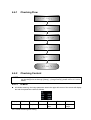
4.3.1 Check Flow .............................................................................................................. 4-2
4.3.2 Checking Content .................................................................................................... 4-2
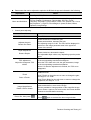
4.4 Function Checking........................................................................................................... 4-5
4.4.1 Checking Flow ......................................................................................................... 4-6
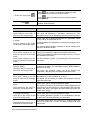
4.4.2 Checking Content .................................................................................................... 4-6
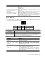
4.5 Performance Test .......................................................................................................... 4-18
4.5.1 Test Process .......................................................................................................... 4-18
4.5.2 Test Content........................................................................................................... 4-18
5
Software Upgrade and Maintenance ........................................................................ 5-1
5.1
5.2
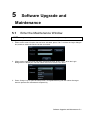
Enter the Maintenance Window ....................................................................................... 5-1
Software Upgrade ........................................................................................................... 5-2
5.2.1 System Upgrade ...................................................................................................... 5-2
5.2.2 Network Update ....................................................................................................... 5-2
5.2.3 Single Update .......................................................................................................... 5-5
5.3 System Restore ............................................................................................................... 5-8
5.3.1 XP Restore .............................................................................................................. 5-8
5.3.2 Doppler Restore ..................................................................................................... 5-10
5.4 Software Maintenance ................................................................................................... 5-12
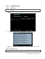
5.4.1 Product Configuration ............................................................................................ 5-12
5.4.2 Log Maintenance ................................................................................................... 5-13
5.4.3 Remote Desktop .................................................................................................... 5-15
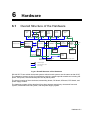
6
Hardware ................................................................................................................... 6-1
6.1
6.2
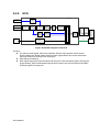
Overall Structure of the Hardware .................................................................................... 6-1
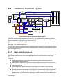
Ultrasound Front-end System .......................................................................................... 6-2
6.2.1 Main Board Front-end .............................................................................................. 6-2
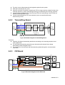
6.2.2 Transmitting Board ................................................................................................... 6-3
6.2.3 CW Board ................................................................................................................ 6-3
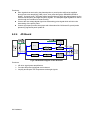
6.2.4 4D Board ................................................................................................................. 6-4
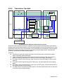
6.2.5 Transducer Sockets ................................................................................................. 6-5
6.2.6 ECG......................................................................................................................... 6-6
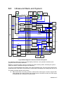
6.3 Ultrasound Back-end System .......................................................................................... 6-7
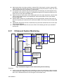
6.3.1 Ultrasound System Monitoring.................................................................................. 6-8
6.3.2 Indicator Light .......................................................................................................... 6-9
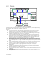
6.3.3 Display................................................................................................................... 6-10
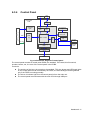
6.3.4 Control Panel .......................................................................................................... 6-11
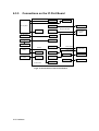
6.3.5 Connections on the IO Port Board .......................................................................... 6-12
ii
6.4
7
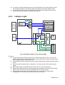
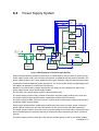
Power Supply System ................................................................................................... 6-13
6.4.1 AC Input Module .................................................................................................... 6-14
6.4.2 AC-DC Power Module ............................................................................................ 6-15
6.4.3 DC-DC Power Board .............................................................................................. 6-15
6.4.4 Battery Module....................................................................................................... 6-17
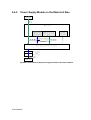
6.4.5 Power Supply Module in the Main Unit Box ............................................................ 6-18
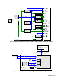
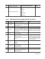
6.4.6 Main Board Power Supply and the Functions ......................................................... 6-21
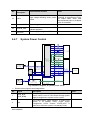
6.4.7 System Power Control............................................................................................ 6-22
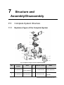
Structure and Assembly/Disassembly .................................................................... 7-1
7.1
Complete System Structure ............................................................................................. 7-1
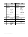
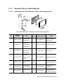
7.1.1 Explosive Figure of the Complete System ................................................................ 7-1
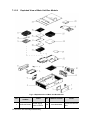
7.1.2 Exploded View of Each Module ................................................................................ 7-3
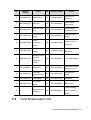
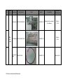
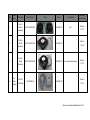
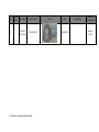
7.2 Field Replaceable Unit .................................................................................................... 7-5
7.3 Structure and Assemble/Disassemble ............................................................................ 7-21
7.3.1 Tools ...................................................................................................................... 7-21
7.3.2 Personnel Requirement.......................................................................................... 7-21
7.3.3 Preparations for Assemble/Disassemble................................................................. 7-21
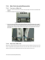
7.3.4 Main Parts Assemble/Disassemble......................................................................... 7-22
7.3.5 Boards Assembly/Disassembly............................................................................... 7-30
7.3.6 Assemble/Disassemble Other Hardware ................................................................ 7-48
8
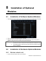
Installation of Optional Modules .............................................................................. 8-1
8.1
8.2
9
Installation of Software Optional Modules ........................................................................ 8-1
Installation of Hardware Optional Modules ....................................................................... 8-1
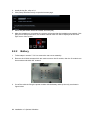
8.2.1 Wireless network card .............................................................................................. 8-1
8.2.2 Battery ..................................................................................................................... 8-2
8.2.3 Pencil Probe Cable .................................................................................................. 8-3
8.2.4 CW Module .............................................................................................................. 8-5
8.2.5 4D Module ............................................................................................................... 8-7
System Diagnosis and Support ............................................................................... 9-1
9.1
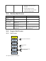
General Status Indicator .................................................................................................. 9-1
9.1.1 Indicators of Control Panel ....................................................................................... 9-1
9.1.2 Power Status Indicators of IO Backplane .................................................................. 9-2
9.1.3 Indicators of Monitor................................................................................................. 9-2
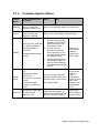
9.1.4 Complete System Status .......................................................................................... 9-3
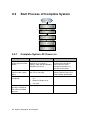
9.2 Start Process of Complete System................................................................................... 9-4
9.2.1 Complete System AC Power on ............................................................................... 9-4
9.2.2 Complete System Batteries Power on ...................................................................... 9-5
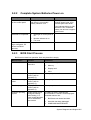
9.2.3 BIOS Start Process .................................................................................................. 9-5
9.2.4 Windows Start Process ............................................................................................ 9-6
9.2.5 Doppler Start Process .............................................................................................. 9-6
9.3 Self-test ........................................................................................................................... 9-8
9.3.1 Introduction .............................................................................................................. 9-8
9.3.2 Maintenance Self-test Performance.......................................................................... 9-8
9.3.3 Description of Self-diagnosis Test Items ................................................................. 9-13
9.4 Warning Information and Abnormal Information.............................................................. 9-34
9.4.1 Batteries Alarm....................................................................................................... 9-34
9.4.2 Fans Alarming ........................................................................................................ 9-37
9.4.3 Abnormal PHV Alarm ............................................................................................. 9-37
9.4.4 Temperature Alarm ................................................................................................. 9-38
iii
9.5
9.4.5 Voltage Alarm......................................................................................................... 9-38
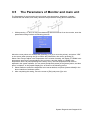
The Parameters of Monitor and main unit ...................................................................... 9-39
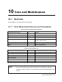
10 Care and Maintenance ............................................................................................ 10-1
10.1 Overview ....................................................................................................................... 10-1
10.1.1 Tools, Measurement Devices and Consumables..................................................... 10-1
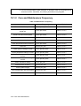
10.1.2 Care and Maintenance Frequency.......................................................................... 10-2
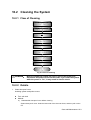
10.2 Cleaning the System ..................................................................................................... 10-3
10.2.1 Flow of Cleaning .................................................................................................... 10-3
10.2.2 Details ................................................................................................................... 10-3
10.3 Maintenance Check....................................................................................................... 10-6
10.3.1 System Function .................................................................................................... 10-6
10.3.2 Peripherals and Options Check .............................................................................. 10-7
10.4 System Maintenance ..................................................................................................... 10-7
10.4.1 Electric Safety Maintenance ................................................................................... 10-7
10.4.2 Mechanical Safety Maintenance ............................................................................. 10-7
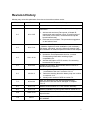
11 Troubleshooting of Regular Malfunctions............................................................. 11-1
11.1 Troubleshooting for System Which Cannot be Powered on ............................................. 11-1
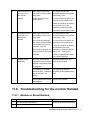
11.1.1 Module or Broad Related ........................................................................................ 11-1
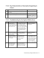
11.1.2 Key Characteristics or Description Supporting to Collect.......................................... 11-1
11.1.3 Troubleshooting for System which cannot be Powered on ....................................... 11-1
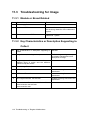
11.2 Troubleshooting for System Which Can not be Activated Normally .................................. 11-2
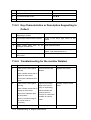
11.2.1 Module or Broad Related ........................................................................................ 11-2
11.2.2 Key Characteristics or Description Supporting to Collect.......................................... 11-3
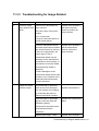
11.2.3 Troubleshooting for the System Malfunctions .......................................................... 11-3
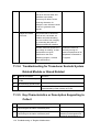
11.3 Troubleshooting for Image .............................................................................................. 11-4
11.3.1 Module or Broad Related ........................................................................................ 11-4
11.3.2 Key Characteristics or Description Supporting to Collect.......................................... 11-4
11.3.3 Troubleshooting for Image Related.......................................................................... 11-5
11.3.4 Troubleshooting for Transducer Sockets System Related Module or Broad Related. 11-6
11.3.5 Key Characteristics or Description Supporting to Collect.......................................... 11-6
11.3.6 Troubleshooting for Transducer Interface Related.................................................... 11-7
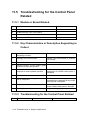
11.4 Troubleshooting for IO Input Related .............................................................................. 11-8
11.4.1 Module or Broad Related ........................................................................................ 11-8
11.4.2 Key Characteristics or Description Supporting to Collect.......................................... 11-8
11.4.3 Troubleshooting for IO Input Related ....................................................................... 11-8
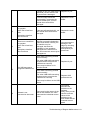
11.5 Troubleshooting for the Control Panel Related .............................................................. 11-10
11.5.1 Module or Broad Related ...................................................................................... 11-10
11.5.2 Key Characteristics or Description Supporting to Collect........................................ 11-10
11.5.3 Troubleshooting for the Control Panel Related....................................................... 11-10
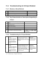
11.6 Troubleshooting for the monitor Related ....................................................................... 11-11
11.6.1 Module or Broad Related ...................................................................................... 11-11
11.6.3 Key Characteristics or Description Supporting to Collect........................................ 11-12
11.6.4 Troubleshooting for the monitor Related ................................................................ 11-12
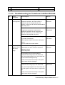
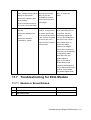
11.7 Troubleshooting for ECG Module .................................................................................. 11-13
11.7.1 Module or Broad Related ...................................................................................... 11-13
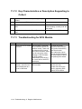
11.7.2 Key Characteristics or Description Supporting to Collect........................................ 11-14
11.7.3 Troubleshooting for ECG Module .......................................................................... 11-14
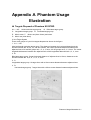
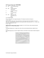
Appendix A
Phantom Usage Illustration..................................................................A-1
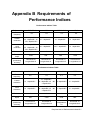
Appendix B
Requirements of Performance Indices ................................................B-1
iv
Appendix C
Boot Screen ..........................................................................................C-1
Appendix D
Electrical Safety Inspection .................................................................D-1
v
Revision History
Mindray may revise this publication from time to time without written notice.
Revision
Date
Reason for Change
1.0
2010.12.01
Initial release
Increase the content of “8.3.3 Description of Self-diagnosis
Test Items”
2.0
2011.3.25
1. Add several test items(Fans speed, IO board ID,
transmission and reception circuit, ID and function of
CW board, LCD monitor, console board and probe
board interface test)
2. Each test item increases “The procession suggestion
on the failure of test”
7.2 Add the Field Replaceable Unit list
3.0
2011.7.12
8 Add the Optional module installation (such as battery,
CW board, 4D board), move the Wireless Network Card
and installation of software optional module to this chapter.
1. Add a model: DC-T6 Vet
4.0
2011.12.30
2. Update the Field Replaceable Unit list, increase
corresponding information including region,
compatibility etc.
3. Add the description of ECG module, IO connecting
board and IO front panel.
5.0
6.0
2012.9.24
2013.4.8
Update the test items, test methods and limit values of
electrical safety inspection.
1.
Change description of the key Reset on IO panel to
“unavailable to the user” in section 3.3.2.2
2.
Delete the warning about the battery loop use number
in section 9.4.1.3
3.
Modify order number of HDD in section 7.2
7.0
2013.6.24
Add “The attentions to the assembly/disassembly,
otherwise the hard disk will be damaged” to Chapter
7.3.6.5
8.0
2014.1.15
Add the Order Number of 17-inch monitor assembly
9.0
2014.7.10
Add the installation of pencil probe cable in section 8.2.3.
10.0
2014.11.25
Delete S-Video/Video-in and Audio-in port, and video/audio
input function.
11.0
2015.7
Section 3.4, add printer SONY UP-D898MD and SONY
UP-X898MD.
I
©2010-2015 Shenzhen Mindray Bio-Medical Electronics Co., Ltd. All rights Reserved.
For this Service Manual, the issue date is 2015-07.
Intellectual Property Statement
SHENZHEN MINDRAY BIO-MEDICAL ELECTRONICS CO., LTD. (hereinafter called Mindray)
owns the intellectual property rights to this Mindray product and this manual. This manual may refer
to information protected by copyright or patents and does not convey any license under the patent
rights or copyright of Mindray, or of others.
Mindray intends to maintain the contents of this manual as confidential information. Disclosure of
the information in this manual in any manner whatsoever without the written permission of Mindray
is strictly forbidden.
Release, amendment, reproduction, distribution, rental, adaptation, translation or any other
derivative work of this manual in any manner whatsoever without the written permission of Mindray
is strictly forbidden.
,
,
,
,
,
BeneView, WATO,
BeneHeart,
are the trademarks, registered or otherwise, of Mindray in China and other
countries. All other trademarks that appear in this manual are used only for informational or
editorial purposes. They are the property of their respective owners.
Applicable for
This service manual is applicable for the service engineers, authorized service personnel and
service representatives of this ultrasound system.
Responsibility on the Manufacturer Party
Mindray is responsible for the effects on safety, reliability and performance of this product, only if:
All installation operations, expansions, changes, modifications and repairs of this product are
conducted by Mindray authorized personnel;
The electrical installation of the relevant room complies with the applicable national and local
requirements;
The product is used in accordance with the instructions for use.
Mindray's obligation or liability under this warranty does not include any transportation or other
charges or liability for direct, indirect or consequential damages or delay resulting from the improper
II
use or application of the product or the use of parts or accessories not approved by Mindray or
repairs by people other than Mindray authorized personnel.
This warranty shall not extend to:
Any Mindray product which has been subjected to misuse, negligence or accident;
Any Mindray product from which Mindray's original serial number tag or product identification
markings have been altered or removed;
Any products of any other manufacturers.
WARNING:
It is important for the hospital or organization that employs this
equipment to carry out a reasonable service/maintenance plan.
Neglect of this may result in machine breakdown or injury of human
health.
Company Contact
Domestic Service Department, Shenzhen Mindray Bio-medical Electronics Co., Ltd.
Mindray Building 22F, Keji 12th Road South, High-tech Industrial Park, Nanshan, Shenzhen
518057, P.R. China
Hotline: 95105652, 4007005652
Tel: +86 755 26582888
Fax: +86 755 26492815
Statement
This service manual describes the product according to the most complete configuration, some of
the content may not apply to the product you are responsible for. If you have any questions, please
contact Mindray Customer Service Department.
Do not attempt to service this equipment unless this service manual has been consulted and is
understood. Failure to do so may result in personnel injury or product damage.
III
1
Safety Precautions
This chapter describes important issues related to safety precautions, as well as the labels and
icons on the ultrasound machine.
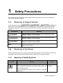
1.1
Meaning of Signal Words
In this operator’s manual,
DANGER,
WARNING,
CAUTION and NOTE are
signal words used to indicate safety and other important instructions. The signal words and their
meanings are defined as follows. Please understand their meanings clearly before reading this
manual.
Signal Word
Meaning
DANGER
Indicates death or serious injury may occur imminently in this
hazardous situation if not avoided.
WARNING
Indicates death or serious injury may occur potentially in this
hazardous situation if not avoided.
CAUTION
Indicates minor or moderate injury may occur potentially in this
hazardous situation if not avoided.
NOTE
1.2
Indicates property damage may occur potentially in this hazardous
situation if not avoided.
Meaning of Symbols
The meaning and location of the safety symbols and warning labels on the ultrasound machine are
described in the following tables, please read them carefully before using the system.
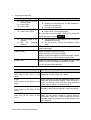
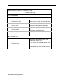
1.2.1
Meaning of Safety Symbols
Symbol
Meaning
Location
Type-BF applied part
The ultrasound transducers connected to this system are
type-BF applied parts.
The ECG module connected to this system is Type-BF
applied part.
Right side of the
I/O panel
Safety Precautions 1-1
General warning, caution, risk of danger.
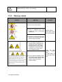
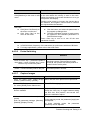
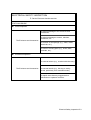
1.2.2
Warning Labels
Symbol
Meaning
Location
(a) Do not sit on the system.
(b) There is explosion risk if the Warning Labels
system is used in flammable
Upper right corner
anesthetics.
of the control panel
(c) Be sure to read the Operator’s
Manual concerning these points
before using the system.
or
(a) Do not place the system on a
sloped surface. Otherwise the
system may slide, resulting in
personal injury or the system
malfunction. Two persons are
required to move the system
over a sloped surface.
(b) Do not open the system covers,
because the high voltage inside
may cause electric shock. Only
service engineers should
remove covers.
1-2 Safety Precautions
Slope and High
Voltage
Caution
Label
Left side panel, at
the right side of the
drive.
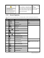
Warning
labels
Inside
the
Don’t connect or disconnect any
ultrasound
other cable before confirm the cable
machine, above the
(with yellow caution) between the
battery module
battery module and the right below
board is disconnected!
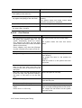
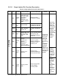
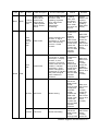
1.2.3
General Symbols
This system uses the symbols listed in the following table, and their meanings are explained as
well.
No.
Symbol
Description
Location
1
Circuit breaker ON/OFF
Power supply panel
2
Power button
Upper left corner of the control
panel
3
Transducer sockets
Below the transducer sockets
4
Network port
I/O Panel
5
Serial port
6
Video signal port
7
Remote port
8
USB port
9
Audio signal port
10
Microphone input jack
11
Unavailable to the user
12
Pencil Probe Port
13
HDD indicating light
14
Battery indicating light
15
Standby mode indicator
16
AC indicator
17
Product serial number
18
Manufacture date
Below the transducer sockets
Upper left corner of the control
panel
Labels
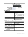
Safety Precautions 1-3
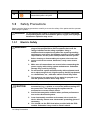
No.
Symbol
Description
Location
The environment-protective application
period of the system is 20 years.
19
1.3
Safety Precautions
Please read the following precautions carefully to ensure the safety of the patient and the operator
when using the probes.
DANGER
1.3.1
Do not operate this system in an atmosphere containing flammable
or explosive gases such as anesthetic gases, oxygen, and hydrogen
because an explosion may occur.
Electric Safety
WARNING:
1. Connect the adapter power plug of this system and power
plugs of the peripherals to wall receptacles that meet the
ratings indicated on the rating nameplate. Using a
multifunctional receptacle may affect the system grounding
performance, and cause the leakage current to exceed safety
requirements. Use the power cable provided with this system.
Before cleaning or disassembling the system, disconnect the
2. power cord from the socket. Otherwise, it may cause electric
shock.
3. Make sure all connections are correct before connecting the
power supply cable during system maintenance. Otherwise
damage may result by hot plug.
4. Do not use this system simultaneously with equipment such
as an electrosurgical unit, high-frequency therapy equipment,
or a defibrillator, etc.; otherwise electric shock may result.
5. This system is not water-proof. If any water is sprayed on or
into the system, electric shock may result.
CAUTION:
1. DO NOT connect or disconnect the system’s power cord or its
accessories (e.g., a printer or a recorder) without turning OFF
the power first. This may damage the system and its
accessories or cause electric shock.
2. Avoid electromagnetic radiation when perform performance
test on the ultrasound system.
3. In an electrostatic sensitive environment, don’t touch the
device directly. Please wear electrostatic protecting gloves if
necessary,
4. You should use the ECG lead wires provided with the ECG
module. Otherwise it may result in electric shock.
1-4 Safety Precautions
1.3.2
Mechanical Safety
WARNING:
1. When this system is moved, please hold the handle. If other
parts of the system are held, it may cause damage due to the
abnormal force. Do not push the system from the left/right side;
otherwise, it may be toppled over.
2. Do not subject the transducers to knocks or drops. Use of a
defective transducer may cause an electric shock.
CAUTION:
1. When move the system on the steps, fasten and fully secure any
peripheral device before moving the system, please take care to
prevent the system from toppling.
2. Do not expose the system to excessive vibration (during the
transportation) to avoid device dropping, collision, or
mechanical damage.
3. Please install the system on a flat plane with the four casters
locked. Otherwise, damage may be resulted by accidental
moving.
4. Move the system only when the system is turned off or in
standby mode, otherwise damage may result to the hard disk.
1.3.3
NOTE:
Personnel Safety
1.
2.
3.
1.3.4
NOTE:
The user is not allowed to open the covers and panel of the system, neither
device disassemble is allowed.
To ensure the system performance and safety, only Mindray engineers or
engineers authorized by Mindray can perform maintenance.
Only technical professionals from Mindray or engineers authorized by Mindray
after training can perform system maintenance.
Others
For detailed operation and other information about the ultrasound system, please refer
to the operator’s manual.
Safety Precautions 1-5
2
Preparations for Installation
2.1
Intended Use
2.1.1
Product Description
DC-N6/DC-T6/DC-T6 Vet are ergonomically designed mobile and ease-of-use machine for
multi-specialty use like adults, pregnant women, pediatric patients and neonates. It is intended for
use in abdominal, gynecology, obstetrics, vascular, small parts, urological, cardiac, and pediatrics
exams in ultrasound diagnostic and scientific research. Imaging modes include B, M, PW, CW,
Color, Power, DirPower, etc.
2.1.2
Dimensions and Weight
Name
Height
1120~1530
Value
(Adjustable)
Length
Width
Weight
790
480
95 (with battery and 4D board)
2.2
Installation Environment
2.2.1
System Environment
Item
Operating Conditions
Storage & Transportation
Conditions
Temperature
0℃~40℃
-20℃~55℃
Humidity
30%~85% (no condensation)
30%~95% (no condensation)
Atmospheric pressure
700hPa~1060hPa
700hPa~1060hPa
Note:
1. The operating temperature for probe 4CD4 and D6-2 is +10℃~+40℃.
2. The storage and transportation temperature for probe 4CD4 and D6-2 is +10℃~+60℃.
WARNING:
Do not use (posit or transport) this system in the conditions other
than those specified.
Preparations for Installation 2-1
NOTE:
Do not use the system where it will be exposed to:
Locations near heat generators
Locations of high humidity
Locations with flammable gases
2.2.2
Electrical Requirements
2.2.2.1
Power Supply Requirement
Voltage
Frequency
Reference power
Circuit breaker
220-240V~, 100-127V~
50/60Hz±3Hz
600VA
250V~, 13A
2.2.2.2
Requirement of Regulated Power Supply
It is recommended to use regulated power supply with good quality and performance such as an
on-line UPS.
2.2.2.3
Grounding Requirement
The power cord of the system is three-wire cable, the earth terminal of which is to be connected to
the earth of the power supply. Ensure the earth of the power supply works properly.
WARNING:
2.2.3
DO NOT connect this system to outlets with the same circuit
breakers and fuses that control the current of devices such as
life-support systems. If this system malfunctions and generates
an over-current, or when there is an instantaneous current at
power ON, the circuit breakers and fuses of the building’s
supply circuit may be tripped.
EMI Limitation
Ultrasound machines are susceptible to Electromagnetic Interference (EMI) from radio frequencies,
magnetic fields, and transient in the air wiring. They also generate EMI.
Possible EMI sources should be identified before the unit is installed.
Electrical and electronic equipment may produce EMI unintentionally as the result of defect.
These sources include: medical lasers, scanners, monitors, cauterizing guns and so on. Besides,
other devices that may result in high frequency electromagnetic interference such as mobile phone,
radio transceiver and wireless remote control toys are not allowed to be presented or used in the
room. Turn off those devices to make sure the ultrasound system can work in a normal way.
2.3
Installation Conditions
2.3.1
Space Requirements
Place the system with necessary peripherals in a position that is convenient for operation:
1. Place the system in a room with good ventilation or an air conditioner.
2. The door is at least 0.8m wide.
2-2 Preparations for Installation
3. Leave at least 20cm clearance around the system to ensure effective cooling.
4. A combination lighting system in the room (dim/bright) is recommended.
5. Except the receptacle dedicated for the ultrasound system, at least 3-4 spare receptacles on
the wall are available for the other medical devices and peripheral devices.
6. Power outlet and place for any external peripheral are within 2 m of each other with peripheral
within 1 m of the unit to connect cables.
2.3.2
Networking Pre-installation Requirements
Both wireless and wired LAN are supported by this ultrasound system.
Data transmission is allowed between different departments or areas without network cable.
Network can be automatically connected after disconnection in case that the device is required to
be moved, wireless transmission task can be recovered after the network resumed to normal
condition. Confirm the network devices and network conditions before the installation.
1. General information: default gateway IP address, and the other routers related information.
2. DICOM application information: DICOM server name, DICOM port, channels, and IP address.
Preparations for Installation 2-3
2.3.3
Confirmation before Installation
Perform the following confirmation before installing the system:
1. The display format used in the region or country where the system is installed.
2. The language used in the region or country where the system is installed.
3. The power voltage used in the region or country where the system is installed.
4. Obstetric formulae and other measurement formulae used in the region or country where the
system is installed.
5. Other settings to be used in the region or country where the system is installed but different
from the factory settings.
6. The doctor’s habits of using the system.
Perform the confirmation above before installing the system. And set up the system to make it
according with the usage of the region or country where the system is installed.
2-4 Preparations for Installation
3
System Installation
3.1
Installation Tools and Duration
Tools: Phillips screwdriver, hex wrench.
Installation duration: 1 person, 1 hour.
3.2
Check after Unpacking
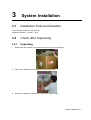
3.2.1
Unpacking
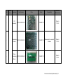
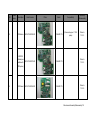
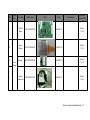
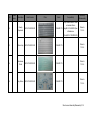
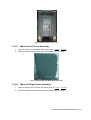
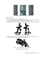
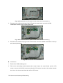
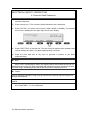
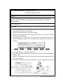
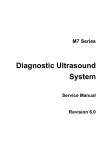
1. Remove the top wooden cover as shown by the arrow in figure below:
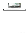
2. Take out the display and the support arm protecting foam.
3. Remove the paper box as shown by the arrow in figure below:
System Installation 3-1
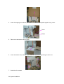
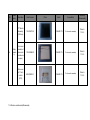
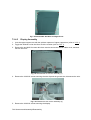
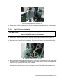
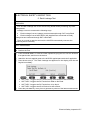
4. Lower the slopping wood board, and stick the wood board with pallet together using velcro.
Velcro
Pallet
5. Take out the transducer carrying case.
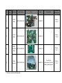
6. Loose the strainer first, and then take out the four that foams protecting the main unit.
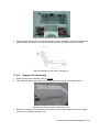
7. Unlock the four casters.
3-2 System Installation
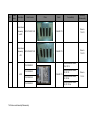
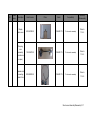
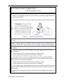
8. Lift the machine, and flip down outside the supporting plancon at both sides of the bottom, and
then push the machine down along the pallet.
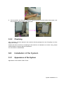
3.2.2
Checking
After unpacking, check the objects in the container with the package list to see if anything is in short
supply or is wrong.
Inspect and make sure there is no damage to the machine, no indentation, no cracks. If any, please
contact Mindray Customer Service Department.
Tel: 9510 5652, or 4007005652.
3.3
Installation of the System
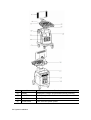
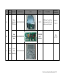
3.3.1
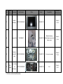
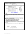
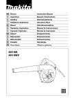
Appearance of the System
Appearance of DC-N6/DC-T6/DC-T6Vet:
System Installation 3-3
No.
Name
Function
(1)
Display
Displays the images and parameters during scanning.
(2)
Control Panel
Operator-system interface or control.
(3)
DVD-RW
DVD-RW drive.
(4)
Power button
Turn on/off the system power.
3-4 System Installation
No.
Name
Function
(5)
Compartment for
placing video
printer
(6)
Transducer socket
(The most left side one is for 4D probe and TEE probe,
and the other 3 sockets are for other probes).
(7)
Caster
Used for fixing or moving the system.
(8)
Transducer& gel
holder
Used for placing transducers and gel temporarily.
(9)
Handle
Used for pushing and moving the system.
(10)
ECG panel
Used for connecting the ECG cable, USB devices and
footswitch.
(11)
Monitor support
arm
Used for supporting and adjusting the height and position
of monitor.
(12)
Table for placing
objects
Used for placing articles and instruments and so on.
(13)
I/O panel
Port panel for input and output signals.
(14)
Power panel
Electrical port panel.
Used for placing B/W video printer.
Sockets connecting transducers and the main unit.
System Installation 3-5
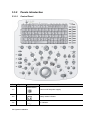
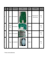
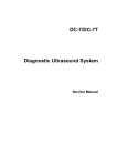
3.3.2
Panels Introduction
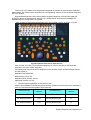
3.3.2.1
Control Panel
No.
Symbol
Name
Function
Power switch
<1>
/
<2>
/
<3>
/
Power on/off the power supply.
Indicator 3
Battery status indicator.
Indicator 2
3-6 System Installation
AC indicator.
No.
Symbol
Name
Function
Indicator 4
<4>
/
Standby mode indicator.
<5>
/
<6>
Esc
Esc
Press to exit the current status to the previous status.
<7>
F1 help
Help
Press to open or close the accompanying help documents.
<8>
F2 iStation
/
Press to enter or exit the patient information management
system.
<9>
F3-F8
/
User defined keys.
<10>
F9
VCR/DVR
/
Reserved key (Enter/exit VCR/DVR playing mode)
<11>
F10 Setup
Preset
Enter/exit preset
<12>
F11 Biopsy
Biopsy
Enter/exit biopsy.
<13>
F12
Physical
Exam
Physical Exam
Enter/exit physical exam.
<14>
Home
/
Home of comments.
<15>
Delete
Word
<16>
/
Alphanumeric
key
The functions are similar with the keys of PC.
<17>
TGC
Slide bar
Time & gain control.
<18>
/
Pressable
knobs
Activate or adjust the soft menu parameter, the item to be
adjusted is corresponding to the soft menu item at the lower
part of the screen.
<19>
/
Pressable
knobs 2
Activate or adjust the soft menu parameter, the item to be
adjusted is corresponding to the soft menu item at the lower
part of the screen.
<20>
/
Pressable
knobs 3
Activate or adjust the soft menu parameter, the item to be
adjusted is corresponding to the soft menu item at the lower
part of the screen.
Indicator 5
Hard disk status indicator.
Delete a recently-added comment text.
Soft menu navigation.
<21>
/
Directional soft
menu controls
Up / down controls are used to turn pages up/down when
there is more than one page for the soft menu.
Left / right keys are used to switch among the different
modes.
<22>
/
Pressable
knobs 4
Activate or adjust the soft menu parameter, the item to be
adjusted is corresponding to the soft menu item at the lower
part of the screen.
<23>
/
Pressable
knobs 5
Activate or adjust the soft menu parameter, the item to be
adjusted is corresponding to the soft menu item at the lower
part of the screen.
System Installation 3-7
No.
Symbol
Name
Function
<24>
iTouch
/
Enter/exit iTouch mode.
<25>
Volume
Volume
Rotate to increase or decrease spectrum volume, and press
to turn on or turn off the sound.
<26>
Patient
Patient
Information
Press to enter the [Patient Info] screen.
<27>
Probe
Probe
Press to select the probe and exam mode.
<28>
Review
Review
To review the stored images.
<29>
Report
Report
Press to open or close the diagnosis reports.
<30>
End Exam
End Exam
Press to end an exam.
<31>
Body Mark
Body Marks
Press to enter or exit the Body Mark status.
<32>
Clear
Clear
Press to clear the comments or measurement calipers on the
screen.
<33>
Arrow
Arrow
Press to enter or exit the arrow comment status.
<34>
Comment
ABC
(Comments)
Press to enter or exit the character comment status.
<35>
M(X)
Pressable
knob
Press to enter M mode, and rotate to adjust M gain; while in
3D/4D mode, rotate the knob to make the 3D image to rotate
around X axis.
<36>
PW(Y)
Pressable
knob
Press to enter PW mode, and rotate to adjust PW (in PW
mode) or CW gain (in CW mode); while in 3D/4D mode,
rotate the knob to make the 3D image to rotate around Y axis.
<37>
Color(Z)
Pressable
knob
<38>
B
Pressable
knob
Press to enter B mode, and rotate to adjust B gain.
<39>
P1
User-defined
key
You can assign a function to the key.
<40>
CW
/
Press to enter CW mode.
<41>
Power
/
Press to enter Power mode.
<42>
P2
/
You can assign a function to the key. (Press to enter 3D/4D
mode on the system configured with 3D/4D module.)
<43>
/
/
<44>
/
/
Press to enter single window mode when the system is in
Dual or Quad mode.
<45>
/
/
Press to enter Quad mode.
Switch image windows in the Quad mode.
<46>
Depth
Depth
Rotate to increase or decrease the imaging depth in scanning
mode.
3-8 System Installation
Press to enter Color mode, and rotate to adjust Color (in color
mode) or Power gain (in Power mode); while in 3D/4D mode,
rotate the knob to make the 3D image to rotate around Z axis.
Press to enter Dual mode from another modes.
Press to switch between the two windows in Dual mode.
No.
Symbol
Name
Function
<47>
Zoom
Zoom
Enter/exit zoom mode.
<48>
Save2
Save 2
Press to save; user-defined key.
<49>
Print
Print
Press to print; user-defined key.
<50>
Save1
Save 1
Press to save; user-defined key.
<51>
Cursor
Cursor
Press to show the cursor.
<52>
Cine
Cine
Press to enter or exit the Cine Review status.
<53>
Measure
Measurement
Press to enter or exit the application measurement mode.
<54>
Update
/
Press to change the currently active window.
Or start/stop image acquisition in iScape or 3D/4D.
<55>
Caliper
Caliper
Press to enter or exit the general measurement mode.
<56>
/
Pressable
knob
Multifunctional knob.
<57>
Menu
Menu
Press to display or hide a mode-specific parameter menu.
<58>
Freeze
Freeze
Press to freeze or unfreeze the image.
<59>
/
Set
Press to confirm an operation, same as the left-button of the
mouse.
<60>
/
Trackball
Roll the trackball to change the cursor position.
<61>
/
Set
Press to confirm an operation, same as the left-button of the
mouse.
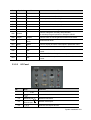
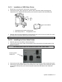
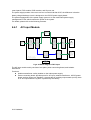
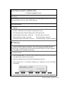
3.3.2.2
I/O Panel
No.
<1><2>
Port
Function
USB port
Connect USB device.
<3>
Unavailable to the user.
<4>
Ethernet port(
Network connection.
<5>
Remote port
Remote control port.
<6>
Connects serial port devices.
System Installation 3-9
No.
Port
Function
<7>
VGA
VGA signal output, connects a monitor or projector.
<8>
DVI Out
DVI signal output.
<9>
S-video IN
Reserved port (Separate video input)
<10>
S-video OUT
Separate video output, connect with the recorder or
video printer.
<11>
Video IN
Reserved port (Composite video input)
<12>
Video OUT
Composite video output, connect with the recorder or
video printer.
<13><14>
Audio IN
Reserved port (Audio input)
<15><16>
Audio OUT
Audio output.
1, 2, 3, 4
Power supply indicators.
<17>
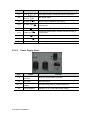
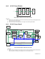
3.3.2.3
Power Supply Panel
No.
Name
<1>
Equipotential
terminal
Used for equipotential connection.
<2>
AC Input
AC power input.
AC auxiliary
output
Provide power ports for peripheral devices.
Circuit breaker
Switches on or off the mains power supply.
<3><4>
<5>
3-10 System Installation
Function
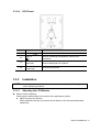
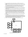
3.3.2.4
No.
<1>
Name
Function
USB port
Connect USB devices.
MIC In
Use for connecting microphone to record vocal
comments.
<3>
ECG lead signal
input port
Connects to ECG leads, to directly obtain the
electrocardiosignal of the patient.
<4>
Pencil probe port
(reserved)
Connect pencil probe.
<2>
3.3.3
Installation
NOTE:
3.3.3.1
ECG Panel
Lock the caster to avoid accidental movement which may result in damage when
do the following operations.
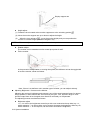
Adjusting the LCD Monitor
Monitor Position Adjusting
Gently hold the bottom edge of the monitor when adjusting its position.
Adjust the angle of inclination
When positioned vertically, the monitor can be tilted for ±20° forward and backward
respectively.
System Installation 3-11
Display support arm
Height adjust
(1) Rotate the lever located at the monitor support arm to the unlocking position
.
(2) Move the monitor support arm up or down to adjust the height.
(3) When the lever points to
, move the monitor slightly and you can position the
monitor in a certain height (4 different heights in all).
NOTE:
Take care of your hands when adjust the monitor up and down.
Rotation adjust
The monitor can be rotated around its central pivot point for ±90°.
Tilt the monitor
In the process of transportation or moving the system, the deflector rod can be toggled left
to level the monitor, shown as follows:
Note: if there is no deflector rod in another type of monitor, you can adjust it directly.
Adjusting Brightness / Contrast on the Monitor
Adjusting the monitor’s brightness and contrast is one of the most important factors for proper
image qualities, if these controls are set incorrectly, the gain, TGC, dynamic range or even
acoustic output have to be changed more often than necessary to compensate.
The adjusting buttons are shown as follows:
Brightness adjust
<1>, <2> refer to the brightness control keys with a sun marked at the top side; key <1>,
which marked a “-” on the top side, can be used to decrease the brightness; while key<2>,
which marked a “+” on the top side, can be used to increase the brightness.
3-12 System Installation
Contrast adjust
<3>, <4> refer to the contrast control keys with a lune marked at the top side; key <3>,
which marked a “-” on the top side, can be used to decrease the contrast, while key <4>,
which marked a “+” on the top side, can be used to increase the contrast.
Load default
Press key <2> and key <3> at the same time, the contrast and brightness will be returned
to the default setting (50 and 50).
NOTE:
3.3.3.2
On the monitor, the brightness adjustment comes before contrast. After readjusting the
monitor’s contrast and brightness, adjust all preset and peripheral settings.
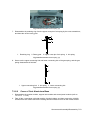
Connecting the Power Cord
1. Push the retaining clamp upward, and insert the power plug into the receptacle, as shown in the
figure below.
Retaining clamp
Receptacle
Power plug
2. Push the retaining clamp downward, and lock the power cord, as shown in the figure below.
System Installation 3-13
3.3.3.3
Connect the ECG
Connect the ECG cable to the corresponding interface on the physiological module.
3.3.3.4
Transducer& Gel Holder
The system provide 5 holders (one holder is for the gel, and the other four are for the transducers).
Pay attention to the sizes of the holders when install them.
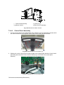
3.3.3.5
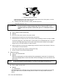
Connecting a Transducer
The system provides 4 transducer sockets in all: when facing with the machine, the leftmost one is
for 4D probe and TEE probe, the other three are for general probes.
1. Turn the lock lever of the transducer connector and keep it in the horizontal position; keep the
cable upward and insert the connector into the port, and then press in fully.
2. Turn the lock handle 90° clockwise to lock it securely (shown as the right figure).
Transducer connector
Lock handle
3. To disconnect the probe: turn the locking lever 90° counterclockwise to the horizontal position.
NOTE:
3.3.3.6
Before inserting the connector into the probe port, inspect the connector pin. If the pin is
bent, do not use the probe until it has been inspected / repaired / replaced.
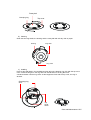
Using the Probe Dust-proof Cover
If a probe port is not used for a long period of time, please use the dustproof cover to protect the
probe port from dust; otherwise bad contact may result.
Transducer socket
Dust-proof
cover
Install the
dust-proof
cover
3-14 System Installation
3.4
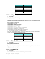
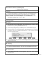
Installing Peripherals
Name
Footswitch
Black / white video printer
Model
971-SWNOM (USB port, two-pedal)
971-SWNOM (USB port, three-pedal)
Analog: MITSUBISHI P93W, SONY UP-897MD, SONY
UP-D898MD, SONY UP-X898MD
Digital: MITSUBISHI P93DC, SONY UP-D897
Color video printer
Analog: SONY UP-20, MITSUBISHI CP910E
Digital: SONY UP-D23MD
HP Color LaserJet CM1015
Graph/ text Printer
HP OfficeJet J3600(HP Officejet J3608 All-in-One)
HP Deskjet D2568
VCR
SONY SVO-9500MD2
DVR
SONY DVO-1000MD
Bar code scanner
Wireless network card
MOTOROLA: LS2208(1-dimensional),
DS6707(1-dimensional)
D-Link: DWA-125
NOTE:
If the ultrasound system can not recognize the SONY UP-X898MD and SONY
UP-D898MD printers automatically, you may need to change the settings on the printer:
push <PUSH ENTER> to enter the main menu and select [DIGITAL]->[DRIVER], and
select [897].
3.4.1
Connecting the Footswitch
Connection
Directly insert the USB port of the footswitch to the system applicable USB ports.
System Installation 3-15
USB port
Function setting
For details, please refer to 3.5.4.1.
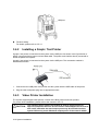
3.4.2
Installing a Graph / Text Printer
A graph / text printer is connected to the system via the USB port. As shown in the figure below, a
graph / text printer has a power cord and data cable. The power cord shall be directly connected to
a wall receptacle as required.
A graph / text printer is connected to the system via the USB port. The connection method is
described as follows:
1. Connect the two USB ports of the printer and the system with the USB cable of the printer.
2. Plug the other end power plug into an appropriate outlet.
3.4.3
Video Printer Installation
The system support digital video printers, consist of the B/W printers and color printers.
For printer driver installation, please refer to the content in 3.5.4.3.
The auxiliary power outlet in the system is used to supply power for
CAUTION: approved peripheral devices. Do not connect other/unapproved devices to
this outlet; otherwise the rated output power may be exceeded and the
system failure may result. Maximum output power of the outlet is 240VA.
3-16 System Installation
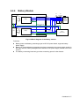
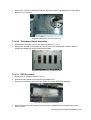
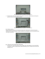
3.4.3.1
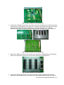
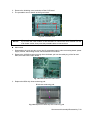
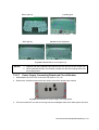
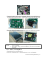
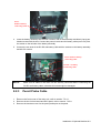
Installation of W/B Video Printer
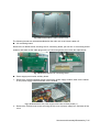
1. Remove the cover board of video printer compartment.
2. Connect the power cable, remote line, and the video connection cable with the printer
respectively (for a digital W/B video printer, just connect the power cable and USB port).
1
2
3
Two limit convex bands
1. Compartment for placing video printer;
2. B/W video printer; 3.
Compartment cover
3. Place the printer in the compartment, locking the foot pad in the limit convex band of the main
unit front cover, so that the printer will not slide freely.
NOTE:
3.4.3.2
Take away the cover board for next use.
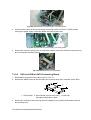
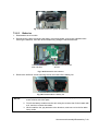
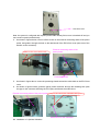
Installing the Color Video Printer
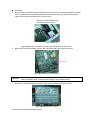
1. Place the printer on the table of ultrasound system.
2. Connect the printer power cable to the auxiliary power output port on the power panel of the
ultrasound system.
NOTE:
The auxiliary power output of the ultrasound system Is 220~240V, 240VA.
Auxiliary power
output port
3. Connect the printer signal cable to the S-Video port on the I/O panel of the ultrasound system.
4. Connect the remote control cable to the remote port on the I/O panel of the ultrasound system
(For a digital video printer, just connect the power cable and USB cable to the ultrasound
system).
System Installation 3-17
Remote port
S-Video
output port
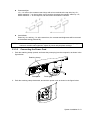
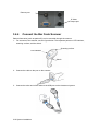
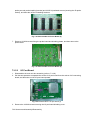
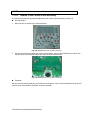
3.4.4
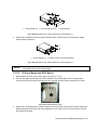
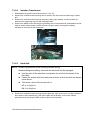
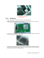
Connect the Bar Code Scanner
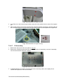
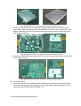
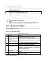
Patient information (such as patient ID) can be recorded through the scanner.
1. For structure of the scanner, see the figure below. The important parts are: LED indicator,
scanning surface, and the switch.
Scanning surface
LED indicator
Switch
2. Connect the cable to the port on the scanner.
3. Connect the other end of the cable to the USB port on the ultrasound system.
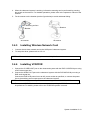
3-18 System Installation
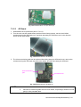
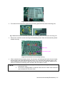
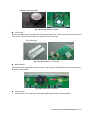
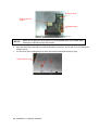
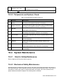
4. When the ultrasound system is working, information scanning can be performed by pressing
the switch on the scanner. For detailed operations, please refer to the operator’s manual of the
scanner.
5. Fix the scanner on the bracket (see the figure below) to avoid accidental falling.
Scanning surface
Bracket
Bracket
2D scanner
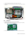
3.4.5
1.
2.
1D scanner
Installing Wireless Network Card
Connect the wireless network card to the USB port of ultrasound system.
To setup the driver, please refer to 3.5.4.4.
NOTE:
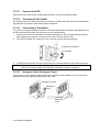
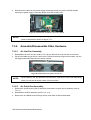
3.4.6
To use wireless network card, please install Key file first.
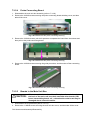
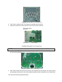
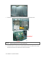
Installing VCR/DVR
1. Connect the S-VIDEO OUT port on the ultrasound system with the DVR S-VIDEO IN port using
a DVR video signal line.
2. Connect the AUDIO OUT port on the ultrasound system with the DVR AUDIO IN port using a
DVR audio signal line.
Connect the DVR/VCR power line to an AC power socket as specified, or connect the power
line to the auxiliary power output port on the ultrasound system.
NOTE:
The auxiliary power output of the ultrasound system Is 220~240V, 240VA.
3. Turn on the VCR/DVR, when the ultrasound system is working, VCR/DVR related working can
be performed. For details, please refer to the VCR/DVR operator’s manual.
System Installation 3-19
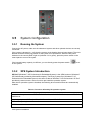
3.5
System Configuration
3.5.1
Running the System
Connect the AC power, make sure the ultrasound system and other optional devices are correctly
connected.
If the system is plugged in – verify that the system circuit breaker has not been tripped. The circuit
breaker should be in the [Up] position for the system to be operational. When the AC power
indicator on the control panel is light on (indicator 2 is in green), press the power switch on the
control panel to turn on the system.
If the internal battery capacity is sufficient, you can directly press the power switch
on the system.
3.5.2
to turn
XPE System Introduction
XP Pro E (Windows™ XP Professional for Embedded System) is the OEM version of Windows™
XP Professional provided by Microsoft® company. The binary system file of Windows™ XP
Professional for Embedded System is the same as that of Windows™ XP Professional. XP Pro E
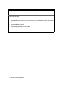
provides the terminal user a series of tools to pre-install the operation system.
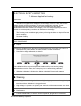
After the XP operation system is installed, the following drivers and functions are automatically
installed:
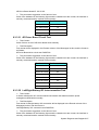
Table 3-1 Functions defined by XP operation system
Install the main board driver: chip group, video card, audio card, and network card.
Install the video printer driver: SONY UP-D23MD driver, SONY UP-D897 driver, and MITSUBISHI
P93D driver.
Install digital printer: HP Deskjet 2568, HP Office 3600, and HP 1015.
USB video capturing box driver.
USB Footswitch.
3-20 System Installation
Install CPU temperature and fan monitoring service.
Hardware self-test program running environment.
Keyboard filter driver.
Install east Asia language: set the language and region as Chinese (PRC).
Install the desktop theme: M7.Theme, no voice.
Power on/Power off/login define.
WINDOWS boot-up interface setting.
No Autorun or autoplay.
No screen saver.
Shut down functions like the fire wall and automatic updating.
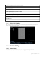
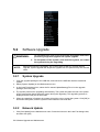
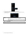
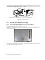
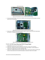
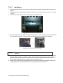
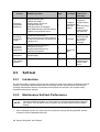
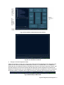
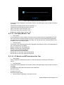
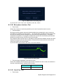
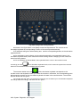
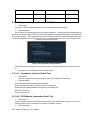
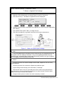
3.5.3
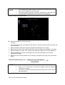
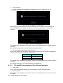
Enter into Doppler
After system is turned on and wait for about 1 minute (for system initialization), it will enter into
Doppler interface, see the figure below:
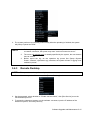
3.5.4
Function Setting
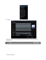
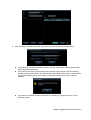
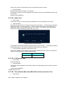
3.5.4.1
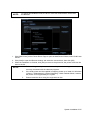
System Preset
Press <Setup> key to open the Setup menu, and click [System Preset] on the menu.
System Installation 3-21
Region
In the Region page, set the system language, date format, date, time and hospital related
information, etc.
NOTE:
Pay attention to the size of the logo when load the hospital logo.
3-22 System Installation
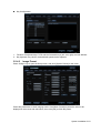
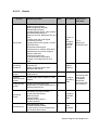
Key Configuration
1. Function of keyboard keys F3-F8 and the footswitch keys (left, mid, right) are user-defined.
2. Key lightness, key volume, and trackball speed can be adjusted.
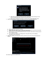
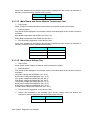
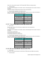
3.5.4.2
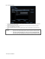
Image Preset
Press <Setup> key to open the Setup menu, and click [System Preset] on the menu.
Preset the parameters in each imaging mode. Click [Menu Preset] to preset the items to be
displayed in the menus and soft menus, then click [OK] to finish the preset.
System Installation 3-23
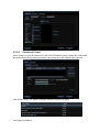
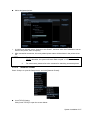
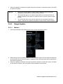
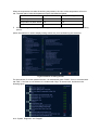
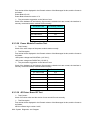
3.5.4.3
Peripheral Preset
Press <Setup> to open the Setup menu, then click [Peripheral Preset] to preset the video printer,
text graph printer (do the setting according to the printer type, and preset the print service).
Click “Printer Driver”, the already installed printers are listed on the page.
3-24 System Installation
NOTE:
For printer MITSUBISHI P93D, the driver of the old model and the new model
are different.
Add local printer
1. Click [Add Printer] on the Printer Driver Page to open the Add Printer Wizard, select “Add Local
Printer”.
2. Click [Next] to open the Browse window, and select the correct driver, then click [OK].
3. When the installation is finished, click [Exit] to return to the printer list, the printer name can be
seen in the list.
NOTE:
1.
2.
Before adding a local printer, make sure the printer is already powered on, and
correctly connected with the ultrasound system.
If the local printer can’t be installed in Doppler, please try to install it in Windows
(<Setup>→[Maintenance]→[Enter Windows]). If both methods failed, it means
the printer is not supported by the system.
3.
Please install the driver using the original driver disc.
System Installation 3-25
Add network printer
1. In the Add Printer Wizard window, select “Search Network Printer”, then click [Next] to open the
Search Network Printer Wizard.
2. Select the targeted printer domain and server the in the drop-down list of Domain List and
Server List respectively. Click [OK].
3. After successful connection, the newly added printer name will be shown in the printer driver
list.
NOTE:
1.
Before connect the network printer, make sure the ultrasound system and the
printer are in the same network domain, and the network is working normally.
2.
When add a network shared printer, if the server has set accessing limitation,
the system will ask the operator to enter the user name and password. Enter
the correct user name and password, click [Auto Connect], and then click [OK].
3-26 System Installation
Add a designated printer
1. In Add Printer Wizard, select “Connect to this Printer”, and then enter the IP address or server
name of the printer, then click [Next].
2. After successful connection, the newly added printer name will be shown in the printer driver
list.
NOTE:
3.5.4.4
1.
The IP address and the server name should be effective, e.g. \\10.2.40.123 or
\\5-HP, otherwise, the system will warn “Bad net path” or “the UNC name is
invalid”.
2.
For other notes, please refer to the contents for searching a network printer.
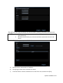
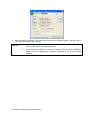
Network Preset
Press <Setup> to open the Setup menu, and click [Network Preset]:
Local TCP/IP Setting
Click [Local TCP/IP] to open the screen below:
System Installation 3-27
1. Input the station name and station location.
2. Select “DHCP”, click [OK].
3. Or, select “Static”, and input the IP address, subnet mask and gateway, then click [OK].
Name
Station Name
Station Location
Current Network Adapter
DHCP
/ Static
IP Address
Subnet Mask
Gateway
Description
Name of the ultrasound system.
Location or department where the system is placed.
Select the network connect method.
If “DHCP” is selected, IP address will be automatically
obtained from DNS server; if “Static” is selected (using
static IP address), you need to enter the IP address.
IP address of the system.
Used to set different network segments.
Used to set the gateway IP.
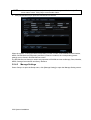
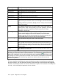
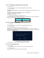
DICOM Preset
NOTE:
Only if DICOM basic option is configured, [DICOM Local], [DICOM Server], [DICOM
Service] are available.
1. Click [DICOM Local] to open the DICOM Local screen.
3-28 System Installation
Enter AE Title, Port, PDU according to the actual situation, and then click [OK] to exit the screen.
NOTE:
1.
AE Title should be the same with the SCU AE Title preset in the server
(PACS/RIS/HIS).
2.
DICOM communication port, which should be the same with the one in the
server.
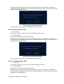
2. Click [DICOM Server] to open the DICOM Server screen.
a)
Input the device name and the IP address.
b)
Click [Ping] to check if the connection is normal.
c)
If the connection is normal, add the server to the Device list, and then click [Exit].
System Installation 3-29
NOTE:
If the currently entered name has already existed, the system will show a tip: “The
server name exists!” Click [OK] to enter another name.
3. Click [DICOM Service] to open the DICOM Service screen.
When the system is configured with DICOM basic function module, and installed DICOM Worklist,
MPPS, DICOM Structured Reporting and Query/ Retrieve modules, the corresponding preset
settings can be found in DICOM Service screen.
The DICOM Service Setting is used to set properties of DICOM services as Storage, Print, Worklist,
MPPS, Storage Commitment and Query/ Retrieve.
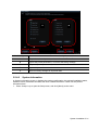
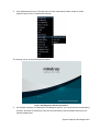
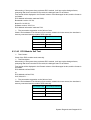
3.5.4.5
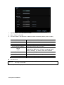
Manage Settings
Press <Setup> to open the Setup menu, click [Manage Setting] to open the Manage Setting screen.
3-30 System Installation
A
C
E
D
Code in figure
3.5.4.6
B
Function description
A
Export the selected presets, and save them in different files
B
Import the preset parameters, or recover the factory settings
C
Export all preset parameters, and save them in a file
D
Import all preset data at one time
E
Recover factory settings for all preset data
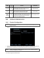
System Information
In System Information screen, it displays the product configuration, the optional installation status,
software version, hardware & boards, and driver related information. Check out the product
information here.
1. Press <Setup> key to open the Setup menu, and click [About] on the menu.
System Installation 3-31
2. Click [About Detail] to open the detailed system information.
3. Click [Save] to export the information in About page and About Detail page in the format of
“*.TXT”.
4. Click [Exit] to return to the Setup menu.
NOTE:
1.
Be sure to confirm the system information before and after the software
maintenance.
2.
Ask the user to save the current system information if necessary.
3-32 System Installation
4
Function Checking and
Testing
4.1
Preparation
4.1.1
Personnel
Function checking and testing of this part shall be carried out by Mindray service engineers and the
user together.
4.1.2
Tool
None.
4.2
Checking System Status
4.2.1
System Running Status
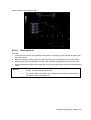
After ultrasound system is turned on, the fan will start working, and no abnormal noise is heard
when the fan is working. System working normally, no abnormal noise and phenomenon.
Check basic system information such as product configuration, options, software version.
Check the preset condition of the system, contrast and brightness of the monitor, optional
devices including transducers, etc.
Check the following items or the log together with the user to confirm the system condition.
1. Any abnormality when the system is running.
2. Occasional abnormalities.
3. Other items requested by customer.
4.2.2
Working Conditions
Check the ambient temperature and humidity. The measurements related to safety features are
particularly sensitive to humidity, measurement position and measuring circuit.
If the insulation feature of the system deteriorates due to the increase of system service time or
system malfunctions, the fluctuation range of measurement results are likely to increase with the
increase in humidity.
Function Checking and Testing 4-1
4.3
General Exam
4.3.1
Check Flow
4.3.2
Checking Content
4.3.2.1
Time and date display
Procedure
Standard
Check the time and date on Region page
(<Setup>→[System Preset]→[Region]).
Check if the time and date are correct, if not,
please preset them again.
4.3.2.2
Check Control Panel
Procedure
Check the functions of all keys and knobs:
Follow the direction: left to right, and up to down.
4-2 Function Checking and Testing
Standard
All keys and knobs are effective.
Procedure
Standard
Function checking of the trackball:
Press the <Freeze> key to enter the
Freeze status.
Press <Measure> to enter into measure
status, do vertical and horizontal
measurement, or do other trackball
operations.
4.3.2.3
The trackball can be rotated easily, the cursor
responds sensitively, the rotation direction is
the same as the direction of the cursor.
Check the LCD Displayer
Procedure
Standard
Adjust LCD brightness
Adjust LCD contrast
Press “+”, the brightness increases; and press “-”, the
brightness decreases.
Adjust color temperature
Press “+”, the contrast increases; and press “-”, the
contrast decreases.
The
setting
path
<Setup>→[Peripheral]→[Input
Display]→Color Temperature
Click [Load Default].
LCD maintenance
is:
& The LCD color temperature changes correspondingly.
Brightness/contrast return to the default setting.
Click each functional button, the LCD responds correctly,
the standard is as follows:
Log in as “Service”, click [Maintenance]
in the Setup menu, then click [Monitor
Test] to go for the monitor test.
1. Light-spot: 0; flash point: 0.
2. The adjoining dark dots are no more than 3 pairs,
and there is no adjoining dark dot in image area.
3. There is no adjoining dark dot of 3 or more than 3.
4. The dark dots are no more than 7 and those in the
image area are no more than 2
5. The distance between bad dots is no less than 5mm.
Note: image area refers to the red rectangle when the
background is black/right.
4.3.2.4
Check DVD R/W
Procedure
Standard
DVD R/W:
Press <Eject> button;
Perform DVD reading
writing.
The DVD driver can be ejected smoothly.
and
Data reading and writing performs normally without
abnormal noise.
Function Checking and Testing 4-3
4.3.2.5
Peripheral Device Checking
Procedure
Standard
Connect the footswitch, check the functions of
footswitch according to the functions listed in Key
Config.
Press the freeze key (the right key), ≡image is
frozen, the freeze menu is displayed; press
the key again, image is unfrozen.
Footswitch:
Press the print key (left key), ≡, B/W printing
starts.
Video printer:
Check if the video printer and ultrasound system
are correctly connected.
Press <Print> key≡the printer begins to work,
no image print deficiency or degradation.
Then check the function of each key.
Switch video output port;
Press <Print> key≡the printer begins to work,
no image print deficiency or degradation.
Text/graph printer:
Check if the printer and ultrasound system are
correctly connected.
Press <Print> key≡the printer begins to work,
no print deficiency or degradation.
Then check the function of each key.
Code bar scanner:
Perform code bar scanning when the ultrasound
system is running normally.
The bar code is correctly displayed on the
screen.
VCR/DVR:
Check if the VCR/DVR and ultrasound system are Audio/video signal can be correctly gathered:
correctly connected.
Video recording can be performed in the
Press <Record> key on the VCR/DVR
normal way.
MIC function checking
4.3.2.6
Audio recording can be performed in the
normal way.
Checking ECG Module
Procedure
Standard
Correctly connect the ECG module and
the ultrasound system, then:
ECG trace is displayed, the heart icon is
displayed at the upper right corner of the
screen.
Set [ECG] as “On”.
The parameters [Speed], [ECG Gain], and
[ECG position] can be adjusted.
ECG signal can be reviewed correctly.
4-4 Function Checking and Testing
4.3.2.7
Checking I/O Ports
Procedure
Checking the main I/O ports:
Besides the
Besides the video/audio ports, USB ports,
the other ports required to be checked
including:
The contents displayed on the
VGA/LCD are the same as those
displayed on the ultrasound system
displayer, no character and image
loss, no color difference, no fluttering
and flicking.
VGA/DVI port;
Smooth communication.
Network port;
USB port data storage/accessing are
normal.
Other USB ports.
4.4
NOTE:
Standard
Function Checking
A complete function inspection is described here, do the checking according to
the actual system configuration.
Function Checking and Testing 4-5
4.4.1
Checking Flow
4.4.2
Checking Content
NOTE:
4.4.2.1
Items that appear in the menu or the soft menus are dependent upon preset, which
can be changed or set through "[Setup] → [Image Preset]"; please refer to 3.5.4.2 for
details.
B Mode
In B Mode scanning, the image parameter area in the upper left corner of the screen will display
the real-time parameter values as follows:
Display
F 5.0
D 17.6
G 50
FR 40
IP 4
DR 60
Parameter
Frequency
Depth
Gain
Frame
Rate
B IP
B Dynamic
Range
4-6 Function Checking and Testing
Parameters that can be adjusted to optimize the B Mode image are indicated in the following.
Adjustment
Control Panel
Menu and Soft Menu
Items
Gain, Depth, TGC, iTouch
Dynamic Range, Focus Number, FOV Position, Line Density, IP, Colorize,
L/R Flip, Rotation, Persistence, Colorize Map, U/D Flip, iTouch,
Frequency, Gray Map, Focus Position, iClear, FOV, Smooth, TSI, Curve,
Gray Rejection, γ, High FR, iTouch Bright, A. power, B Steer, iBeam,
Trapezoid, Image Merge
1. Control panel adjusting
Procedure
Standard
Press <B> button
Enter B Mode.
Adjutant the gain:
Rotate clockwise, increase the gain;
Rotate anticlockwise, decrease the gain;
Rotate <B> button
Depth Adjustment
Rotate <Depth>
The adjusting range is 0-100. The value will be displayed in
real-time in the image parameter area in the upper left
corner of the screen.
Rotate clockwise, increase the depth;
Rotate clockwise, decrease the depth;
The adjustable depth values vary depending upon the probe
types.
TGC adjustment
Move the TGC slider to the right, the gain increases, image
of the corresponding area becomes brighter.
Adjust the 8-segment TGC
sliders
Move the TGC slider to the left, the gain decreases, image
of the corresponding area becomes darker.
About 1.5s after the adjustment is finished, the TGC curve
disappears.
Image auto optimization, an iTouch icon is displayed in the
parameter area.
iTouch
Press <iTouch>
Click [iTouch] on the soft menu or menu to change the gain,
the range is: -12-12dB.
Click [iTouch Bright] on the soft menu or menu to change the
brightness, the range is: -2-+2.
Image Magnification
Rotate <Zoom> button
Rotate clockwise, zoom in the image (the max. factor is 10);
rotate anticlockwise, zoom out the image
Roll the trackball to change position of the magnified image.
Press <Zoom> again to exit zoom mode, the current window
restores to the state before zooming;
Enter into dual B mode, the right side image is activated.
Press <B>, then press
Press
again to activate the other image window.
Function Checking and Testing 4-7
Press
for 4 times, four B images displayed, three
images are frozen, and one image is active.
Press <B>, then press
Press
again to update the active image windows
among the four.
Press
In non-single image window mode, enter into single image
window mode (B mode).
2. Menu and Soft Menu Adjusting
Procedure
Standard
Frequency adjust
Press <Set> key or click the parameter, the value changes in
real time (B frequency-F, harmonic frequency-H). The
adjustable range varies depending upon the transducer types.
Click [Freq] on the menu or
soft menu of B image mode.
A. power
Click [A. power] on the menu
or soft menu of B image mode.
Press <Set> key or click the parameter, the adjustable range
is 10%-100%, in increments of 3%.
TI and MI values are displayed in real time in the upper part of
the screen.
You should perform exams according to actual situation and
follow the ALARA Principle.
Focus
Click [Focus Position] on the
menu or soft menu of B image
mode.
Click [Focus Position] to adjust the position of the focus
Click [Focus Number] on the
menu or soft menu of B image
mode.
The focus position symbol
the image.
Dynamic Range
Press <Set> key or click the parameter button, the value
changes in real time, the adjustable range is 30dB-160dB, in
increments of 5dB.
Click [Dyn Ra.] on the menu or
soft menu of B image mode.
Line Density
Click [Line Density] on the
menu or soft menu of B image
mode.
Click [Focus Number] to adjust the number of focus (1-4 focus
are available in B mode).
is displayed on the right side of
The more the dynamic range, the more specific the
information, and the lower the contrast with more noise.
Press <Set> key or click the parameter button. Four
adjustable levels are available: M, H, UH, L.
The higher the line density, the higher the resolution, and the
lower the frame rate.
Press <Set> key or click the parameter button.
Clear
Click [iClear] on the menu or
soft menu of B image mode.
The system provides 5 levels of iClear effects adjustment, off
represents no iClear is turned on, and the bigger the value the
stronger the effect. The bigger the value the more clearer the
profile of the image.
IP (Image Processing)
Press <Set> key or click the parameter button.
Click [IP] on the menu or soft
menu of B image mode.
The system provides 8 groups of IP combinations, and the
specific value of each parameter can be preset.
FR
In single B mode when THI is turned on, click the [High FR]
item in the soft menu or menu to obtain images with high
frame rates.
Click [High FR] on the menu or
soft menu of B image mode.
4-8 Function Checking and Testing
Procedure
Standard
Click [U/D Flip]/ [L/R Flip] on the menu or soft menu of B
image mode.
Click [U/D Flip]/ [L/R Flip] on
the menu or soft menu of B
image mode.
Click [Rotation] on the menu or
soft menu of B image mode.
Click [Rotation].
Image can be rotated by the manners in angle of 0°, 90°,
180°, 270°.
When the image is rotated in the angle of 90° or 270°, the
depth scale is displayed on the upper part of the screen.
When you flip or rotate an image, the “M” mark will change its
position on the screen; the M mark is located in the upper left
corner of the imaging area by default.
4.4.2.2
M Mode
In M mode scanning, the image parameter area in the upper left corner of the screen displays
the real-time parameter values as follows:
Display
V3
IP 6
DR 65
G 45
Parameter
M
Speed
M IP
M Dynamic
Range
M Gain
Parameters that can be adjusted to optimize the M mode image are indicated in the following.
Adjustment
Control Panel
Menu and Soft Menu
Items
Gain, TGC, Depth
IP, Time Mark, Speed, Colorize, Colorize Map, Acoustic Power, Edge
Enhance, Frequency, Gray Map, Focus Position, Dynamic Range, M
Soften, Curve, Gray Rejection, γ, Display Format
1. Control panel adjusting
Procedure
Standard
Press <M>
Press <M> on the control panel, and roll the trackball to
adjust the sampling line.
Press <M> again, or press
<Update>
Press [M] on the control panel again to enter M Mode,
then you can observe the tissue motion along with
anatomical images of B Mode.
Rotate clockwise, increase the gain;
Rotate anticlockwise, decrease the gain;
Rotate <M>
The adjusting range is 0-100. The value will be displayed
in real-time in the image parameter area in the upper left
corner of the screen.
Press <Update>
Switch between real time B mode and freeze B mode.
Function Checking and Testing 4-9
Tips:
Adjustment of the depth or TGC to the B Mode image will lead to corresponding changes
in M Mode image.
2. Menu and Soft Menu Adjusting
Procedure
Standard
Speed
Press <Set> key or click the parameter button.
Click [Speed] on the menu or soft
menu of M image mode.
There are 6 levels of scan speed available, the
smaller the value the faster the speed.
Time Mark
Click [Time Mark] on the menu or
soft menu of M image mode.
Press <Set> to turn on or turn off the function.
Display Format
Press <Set> key or click the parameter button to
change the display format. There are 4 formats
available for image display: L/R, V1:1, V1:2, Full.
Click [Display Format] on the menu
or soft menu of M image mode.
Tips:
During M Mode scanning, frequency and acoustic power of the transducer are synchronous
with that of B Mode.
4.4.2.3
Color Mode
In Color mode scanning, the image parameter area in the upper left corner of the screen
displays the real-time parameter values as follows:
Display
F 3.3
G38
IP 1
WF 43
PRF 0.4k
Parameter
Frequency
Color
Gain
Color IP
Color Wall
Filter
Pulse
Repetition
Frequency
PRF
Parameters that can be adjusted to optimize the Color mode image are indicated in the
following
Adjustment
Control Panel
Menu and Soft Menu
Items
Gain, Depth
B/C Wide, Frequency, Priority, Baseline, Packet Size, Dual Live, Color IP,
Map, A. power, Focus Position, Scale, Flow State, WF, Invert, Line
Density, Smooth, Persistence, B Display, Steer
4-10 Function Checking and Testing
1. Control panel adjusting
Procedure
Standard
Press <Color>
Enter into B+Color mode
Roll the trackball
Press <Set> key, then rotate
the trackball
The ROI box is displayed in solid line, roll the
trackball to change the position
The ROI box is displayed in dotted line, roll
the trackball to change the size.
Press <Set> to switch between the solid line and the
dotted line status.
Color Gain
Rotate clockwise, increase the gain;
Rotate <Color>
Rotate anticlockwise, decrease the gain;
The adjusting range is 0-100. The value will be
displayed in real-time in the image parameter area in
the upper left corner of the screen.
Tips:
In Color Mode, acoustic power is synchronous with that of B Mode. Adjustment of the depth or
zoom to the B Mode image will lead to corresponding changes in Color Mode image.
2. Adjustments through image menus or soft menus
Procedure
Packet Size
Click [Packet Size] on the menu or
soft menu of M image mode.
Flow State
Click [Flow State] on the menu or
soft menu of B image mode.
Standard
Press <Set> key or click the parameter button.
There are 4 levels of packet size provided, 0 represents
no packet size control and the bigger the value the
higher the sensitivity.
Press <Set> key or click the parameter button.
There are 3 levels provided to adjust: L, M, H.
Click [Scale] on the menu or soft
menu.
Press <Set> key or click the parameter button. Use low
PRF to observe low-velocity flows, and use high PRF to
observe high-velocity flows. To provide a much clearer
color flow image.
Baseline
Press <Set> key or click the parameter button (the
range is -8~8).
Scale
Click [Baseline] on the menu or soft
menu.
Positive value means to increase the signals above the
baseline, and negative value means to increase the
signals below the baseline.
Tips: For the image optimization and exam, please refer to that of B mode.
4.4.2.4
Power Mode
In Power mode scanning, the image parameter area in the upper left corner of the screen
displays the real-time parameter values as follows:
Function Checking and Testing 4-11
Display
F 2.5
G 38
IP 1
WF32
PRF 0.3k
Parameter
Frequency
Power
Gain
Power IP
Power Wall
Filter
Pulse
Repetition
Frequency
PRF
Parameters that can be adjusted to optimize the Power mode image are indicated in the
following.
Type
Control Panel
Menu and Soft Menu
Parameter
Gain, TGC, Depth
B/C Wide, Frequency, Priority, Dynamic Range, Packet Size, Dual Live,
Power IP, Map, Acoustic Power, Focus Position, Scale, Flow State, Wall
Filter, Invert, Line Density, Smooth, Persistence, B Display, Steer
1. Control panel adjusting
Procedure
Standard
Press <Power>
Enter into B+Power mode.
Roll the trackball
Press <Set> key, then rotate
the trackball
The ROI box is displayed in solid line, roll
the trackball to change the position
The ROI box is displayed in dotted line, roll
the trackball to change the size.
Press <Set> to switch between the solid line and the
dotted line status.
Power Gain
Rotate clockwise, increase the gain;
Rotate <Color>
Rotate anticlockwise, decrease the gain;
The adjusting range is 0-100. The value will be
displayed in real-time in the image parameter area in
the upper left corner of the screen.
Tips:
In Color Mode, acoustic power is synchronous with that of B Mode. Adjustment of
the depth or zoom to the B Mode image will lead to corresponding changes in Color
Mode image.
The adjustable parameters of Power Mode are consistent with those of the Color
Mode.
2. Menu and Soft Menu Adjusting
Procedure
Standard
Press <Set> key or click the parameter button.
Map
Click [Map] on the menu or soft
menu.
Flow State
Click [Flow State] on the menu or
soft menu of B image mode.
4-12 Function Checking and Testing
There are 8 kinds of maps provided: P0-3 belong to
Power Mode maps, while dP0-3 belong to Directional
Power Mode maps.
The Power maps provide information of blood flow,
which are highly sensitive to the low-velocity flows. The
Directional Power maps provide information of flow
direction.
Press <Set> key or click the parameter button.
There are 3 levels provided to adjust: L, M, H.
Procedure
Standard
Tips:
For image optimization, please refer to that of B mode.
4.4.2.5
PW
PW/CW Mode
The parameters will be displayed in the image parameter area on the left part of the screen as
follows:
Display
F 2.5
G 60
PRF 3.6k
WF295
SVD 8.8
SV 3.0
Frequency
Gain
Pulse
Repetition
Frequency
PRF
WF
(Wall
Filter)
SV
Position
SV Size
F 3.3
G 30
WF407
PRF 7.3k
SVD 35.0
Frequency
Gain
WF (Wall
Filter)
Pulse Repetition
Frequency PRF
SV Position
Parameters
CW
Display
Parameters
Parameters that can be adjusted to optimize the PW/ CW mode image are indicated in the
following.
Adjustment
Items
Control Panel
Gain, TGC, Depth
PW
Invert, SV, WF, Frequency, Duplex/Triplex, V Max, V Mean, Audio, Trace
Area, Colorize Map, Speed, Acoustic Power, Trace Sensitivity, T/F Res,
Gray Map, Dynamic Range, Scale, Baseline, Colorize, Quick Angle,
Angle, Trace Smooth, Time Mark, HPRF, Curve, Gray Rejection, γ,
Display Format, Auto Calculation, Auto Calculation Parameter, PW Steer
CW
WF, Invert, Colorize Map, Frequency, Speed, V Max, V Mean, Dynamic
Range, Audio, Trace Area, Trace Sensitivity, Gray Map, Scale, Baseline,
Colorize, Quick Angle, Angle, Acoustic Power, Trace Smooth, Time Mark,
T/F Res, Curve, Gray Rejection, γ, Display Format, Auto Calculation, Auto
Calculation Parameter
Soft Menu &
Menu
NOTE:
1
Most of the parameters are the same for the PW Mode and CW Mode, so the both
are combined together to be introduced here.
2
Only phased probes support CW mode.
3
Items as iTouch, SV, steer, Duplex, Triplex and HPRF, are not available in the CW
mode.
Function Checking and Testing 4-13
1. Control panel adjusting
Procedure
In B mode or B+Color
(Power) mode
Press <PW>
Press <CW>
Press <PW> again
Press <CW> again
Standard
Displays the sampling line, roll the trackball to
adjust the sampling line.
The same as PW mode.
Enter into B+PW imaging mode.
Enter into B+CW imaging mode.
The sampling correction angle value will be displayed
above the image, such as
Roll the trackball to the
right/left.
Roll
the
trackball
up/down
.
Set the position of the sample line by moving the
trackball left and right
Set the SVD by moving the trackball up and
down
Press <Update>
Press <Update> to switch between the real-time B and
freezing B images.
Rotate <Depth>
Rotate clockwise, increase the depth;
Rotate clockwise, decrease the depth;
When you adjust the depth of the B Mode image, related
changes will occur in PW/CW Mode image as well.
Rotate <PW>
Rotate the knob clockwise to increases the gain, and
rotate the knob anticlockwise to decrease the gain.
PW or CW gain can be adjusted.
2. Menu and Soft Menu Adjusting
Procedure
Standard
SV
Press <Set> key or click the parameter button.
Click [SV] on the menu or soft Adjust the SV size (range: 0.5~20mm)
menu.
Angle
Click [Angle] on the menu or soft
menu.
Scale
Click [Scale] on the menu or soft
menu.
WF (Wall Filter)
Click [WF] on the menu or soft
menu.
4-14 Function Checking and Testing
Press <Set> key or click the parameter button, try to
adjust the angle between Doppler vector and flow to
make the velocity more accurate. The adjustable
angle range is -80~80°, in increments of 1°.
Press <Set> key or click the parameter button. The
available values vary by frequency, probe and depth.
Press <Set> key or click the parameter button. It
filters out low-velocity signals to provide effective
information. There are 7 levels of wall filter function
available, adjust according to the actual situation and
the transducer.
Procedure
Standard
Baseline
Press <Set> key or click the parameter button. Refers
to the area where the velocity is zero in the scale.
Adjust it according to the actual situation so as to get
an optimum flow display.
Click [Baseline] on the menu or soft
menu.
Positive value means to increase the signals above
the baseline, and negative value means to increase
the signals below the baseline.
Auto Calc
Click [Auto Calc Param] on
the menu or soft menu.
Click [Auto Calc] on the
menu or soft menu.
Click the button, and select the parameters in
the popped up dialogue box.
The Auto Calculation function is used to trace
the spectrum and calculate parameters of
PW/CW-Mode image.
Press <Set> key to turn on or turn off the auto
calculation function.
Tips:
4.4.2.6
In PW/CW Mode, frequency of the transducer is synchronous with that of B Mode.
For image optimization, please refer to that of M mode.
Probe Switching
Procedure
Press <Freeze> key→ connect the probe to
the system→ press <Freeze> key→ press
<Probe> key to select the probe.
Press <Freeze> key→ disconnect the
probe→ connect another probe to the port
4.4.2.7
Standard
Connect a convex probe to probe socket A,
and then connect a linear probe to probe
socket B, the operator can select probe A or
probe B as the active probe.
The system can recognize the newly
connected probe in no time.
Capture Images
Procedure
Standard
Open the Setup menu, select [Image
Preset]→[Menu Preset]→[3D/4D]
Menu and soft menu preset can be performed.
Press <3D/4D> key
Or, select [3D/4D] on the Other menu
Enter 3D/4D imaging preparation status.
Acquisition preparation
Roll the trackball
Adjust the ROI position;
Click the soft menu buttons (already
preset)
The parameters can be set.
Such as parameter package, [direction],
[Method], [Display Format]
Press the <Set> key to toggle between setting
the ROI size, ROI position, and curved VOI.
Move the trackball to adjust.
In fan scanning mode, the parameter [angle] can
be adjusted.
In linear scanning mode,
[Distance] can be adjusted.
the
parameter
Function Checking and Testing 4-15
Procedure
Standard
Press <Update>;
Click [Start] on the soft menu.
Image acquisition starts
Press <Freeze> key / press <Update>
key again /click [Stop] on the soft menu
End the image capture and enter into image
viewing.
The system enters into image review status
when the acquisition is completed.
Press <Esc>/<Update>/<Freeze> key
Returns to image acquisition preparation.
Press <B>/<3D/4D> key
Or, press <Esc> for twice.
Exit image acquisition.
4.4.2.8
Cine Review
Procedure
Standard
Press [Freeze] key to freeze an image, and
the [Cine] key indicator lights on. The
system automatically enters the manual
cine status.(It has been set that when
system enters into freeze mode, the default
status is cine review.)
The system enters into cine review status
The system enters into auto cine review
status.
Press <iStation> key, then click [Review];
or press <Review> key to open a cine file.
Roll the trackball
Manual cine review
Click [Auto Play] on the menu or soft menu.
Auto play function is turned on, adjust the soft
menu button []
The greater the value is, the quicker the
speed is.
When the value is 0, the system exits auto
play mode.
Move the cursor onto the desired start
point of the cine loop, click [Set First
Frame] in the menu or soft menu to set the
start point.
Set the start point of cine loop.
Move the cursor onto the desired end point Set the end point of cine loop.
of the cine loop, click [Set Last Frame] in
the menu or soft menu to set the start
point.
Click [Auto Play] again
Review region is confined to the set start
point and end point.
Then press the [Cine] key again.
Cine review stops.
Press the <Freeze> key to unfreeze the
image.
Freeze indicator light is off, the system will
return to image scanning and exit cine review.
Press <Cine> or <Esc> key.
The images are still frozen but the system
exits cine review.
4-16 Function Checking and Testing
Procedure
4.4.2.9
Standard
Measurement
Procedure
Standard
In B image mode:
Press <Measure>:
Press <Caliper> key
The
system
measurements
enters
application
The system enters general measurement
mode.
Perform any 1-2 measurements (e.g.,
length, area), the results will display at the
lower part of the image.
Press the same key again or press <Esc>.
Exits measurement.
Do the same operation in other image Application measurements are classified into
modes.
different application packages, do the
application measurements selectively.
4.4.2.10 Patient Information Management
Procedure
Standard
Press <Save 1> or <Save 2> (the function
already set) during image scanning
Image will be saved to the patient database,
and a thumbnail will be displayed at the
right part of the screen.
Open
[Setup]
→[System
Preset]→”General”, then check “Send/Print
Image after End Exam” in the Patient
Management area.
The system automatically sends the images
of the exam to the default DICOM storage
server or print server.
Press <End Exam> during image scanning
Press <Review> key.
Click [Exit] on the Review screen;
or, press <Review> again, or,
press <Esc> key
The system enters into image
review mode.
The system exits image review
mode.
Function Checking and Testing 4-17
Procedure
Click [iVision] on the Other menu;
or press user-defined iVision key.
Select the contents to be
demonstrated, and select the
demo mode in the iVision screen.
Then select an item already added
to the list and click [Start]
When the demonstration is
finished, click [Exit] or press
<Esc>.
Press <iStation> key to enter patient
information management (iStation page)
4.5
Performance Test
4.5.1
Test Process
4.5.2
Test Content
Standard
Open iVision screen:
Demonstration begins.
Image files are played according to
file names one by one (including
the image of system-relevant and
PC-compatible format).
The
system
exits
the
demonstration.
The saved patient information (images) can
be found, and the patient information can
be:
Backed up/ Restored
Sent (To DICOM or network
storage)
Requirements:
1. Monitor: set the contrast and brightness at the clinical application value (or the default status)
2. Operation environment: dark room, simulating the clinical application environment.
3. Scanning techniques: contact the probe with the acoustic window of the phantom, no spacing
nor pressing.
Tips:
4-18 Function Checking and Testing
1. For the testing phantoms, please refer to Appendix A.
2. For the testing standards, please refer to Appendix B.
4.5.2.1
Resolution
Transverse resolution
Test Step:
1. Cover the scan surface of the phantom with water or couple gel, gently contact the probe with
the scan surface, making the transverse resolution testing targets to be displayed around the
midline of the image.
2. Adjust the focus point focuses at the position where the transverse resolution testing targets
are displayed.
3. Adjust parameters like gain, dynamic range, TGC, making the background tissue unseen, just
displaying the target image clearly.
4. In condition that the transverse resolution testing targets are horizontally displayed, record the
minimal distance of two targets that can be clearly recognized.
5. Repeat the operation above for the transverse resolution testing targets at other depths.
Image is shown as the figure below:
Axial resolution
Test step:
1. Cover the scan surface of the phantom with water or couple gel, gently contact the probe with
the scan surface, making the axis resolution testing targets to be displayed around the midline
of the image.
2. Adjust the focus point focuses at the position where the axis resolution testing targets are
displayed.
3. Adjust parameters like gain, dynamic range, TGC, making the background tissue unseen, just
displaying the target image clearly.
Function Checking and Testing 4-19
4. Record the minimal distance of two axis resolution testing targets that can be clearly
recognized.
5. Repeat the operation above for the axis resolution testing targets at other depths.
NOTE:
1.
2.
4.5.2.2
When use the convex probe, keep the transverse resolution testing targets to
be displayed near the midline.
When use a linear probe with steer function, do not turn on the steer function
when perform the transverse resolution test.
3.
Zoom in the region where the targets located if necessary.
4.
The diameter of the target point at a certain depth is equal to the transverse
resolution at the depth.
Maximum Depth
Test step:
1. Cover the scan surface of the phantom with water or couple gel, gently contact the probe with
the scan surface
2. Set the system display depth according to the expected maximum available depth of the probe
in use.
3. Adjust the focus point to the fast, and AP at the maximum value.
4. Set gain, contrast, TGC at a greater value, but no halation nor defocus is allowed.
5. Record the depth of the fast target (the target can be seen clearly).
NOTE:
1.
Greater gain will result in greater the noise, which may weaken the echo.
2.
When use a linear probe, please completely contact the probe with the scan
surface, no side clearance is allowed.
When use a convex or phased-array probe, make the axis targets to be displayed
at the middle of the scanning image.
When system is not frozen, the fast field target information may be similar with
that of the noise, do not use this target.
3.
4.
Image is shown as the figure below:
4-20 Function Checking and Testing
4.5.2.3
Geometric Position Accuracy
Longitudinal geometric position accuracy
Test step:
1. Do adjustments as the way in testing the maximum depth.
2. Record the distance by 20mm each segment on the longitudinal targets line using the
measurement caliper;
3. Select the value with the greatest error (to 20mm), calculate the accuracy using the formula
below:
Function Checking and Testing 4-21
NOTE:
1.
2.
The measurement caliper should be posited at the upper edge of the
target, not the middle nor the lower edge.
The scanning plane should be vertical to the target line, that means the
scanning plane is parallel with the cross-section of the phantom
Image is shown as the figure below:
Transverse geometric position accuracy
Test step:
1. Cover the scan surface of the phantom with water or couple gel, gently contact the probe with
the scan surface
2. Adjust the depth, making the transverse targets to be displayed in the image.
3. Adjust the focus point to be posited beside the transverse targets (the standard is not clear);
4. Adjust parameters like gain, TGC, making each transverse targets to be clearly displayed.
5. Record the distance by 20mm each segment on the transverse targets line using the
measurement caliper;
6. Select the value with the greatest error (to 20mm), calculate the accuracy using the formula
below:
NOTE:
1.
When use a linear probe, record the transverse distance by segment.
2.
When use a convex probe, all transverse targets should be displayed
integrally in an image.
The measure caliper should be posited at the upper side or lower side of
the target center.
3.
4-22 Function Checking and Testing
Image is shown as the figure below:
4.5.2.4
Blackout Area
Test step:
1. Cover the scan surface of the phantom with water or couple gel, gently contact the probe with
the scan surface
2. Adjust the depth at a lower value, and set the focus at the nearest place to the scan surface.
3. Decrease the value of parameters like AP, Gain until the background noise just can be seen.
4. Record the smallest depth of the target that can be seen clearly, that value is the blackout area
value.
NOTE:
1.
2.
When use a linear probe, please completely contact the probe with the scan
surface, no side clearance is allowed.
For convex probe, the targets in the blackout area should be positioned on
the midline of the scanning plane.
Function Checking and Testing 4-23
Image is shown as the figure below:
4-24 Function Checking and Testing
5
Software Upgrade and
Maintenance
5.1
NOTE:
Enter the Maintenance Window
Log on the system with the identity of Service before perform system maintenance.
To log on the system:
1. When access control function has not been activated: press “Ctrl+/” to show the Login dialogue
box, and then select the Service as the user name.
2. When access control function has been activated already: press “Ctrl+/” when the Login
dialogue box is displayed, and then select the Service as the user name.
3. Press <Setup> key to open the Setup menu, click [Maintenance] and then select the target
items to perform the maintenance respectively.
Software Upgrade and Maintenance 5-1
5.2
Software Upgrade
WARNING:
1. To avoid data loss, back up the preset data and patient data before
performing single item upgrade and system upgrade.
2. Do not power off the system, shut down the system, nor restart
the system during the upgrading.
NOTE:
5.2.1
Before performing the upgrading, log on the system as Service. Except network
upgrade, system upgrade and single item upgrade can’t be performed by the external
users.
System Upgrade
1. Copy the upgrade package to the USB disk, and connect the USB disk with the ultrasound
system.
2. Select [System Update] on the Maintenance menu.
3. In the Load File dialogue box, select the file named UpdateStrategyFile.ini in the upgrade
package, then click [OK].
4. The system performs the upgrading automatically. The system will warn the user not to power
off the system/shut down/restart the system during the upgrading. The upgrading process is
displayed at the lower part of the screen.
5. When the upgrading is finished, the system will ask the user to restart the system. Click [OK] to
shut down the system, and the system will be restarted 5 seconds later.
5.2.2
Network Update
1. Click [Net Update] on the Maintenance menu. Select the license in the Load File dialogue box,
and then click [OK].
5-2 Software Upgrade and Maintenance
2. After the license verification passed, the system will open the following dialogue box.
Click [Abort] to end the downloading, and the already loaded down data on the hard disk
will be deleted automatically.
Click [Pause] to exit the current dialogue box and the system will give out the following
prompt (see the figure below). The data already loaded down will be kept on the hard disk,
and the downloading can be continued by selecting the same license in the next net
updating.
If you select the different license in the next net updating, the system will give out the
following prompt:
Software Upgrade and Maintenance 5-3
Click [Yes], the system will delete the already loaded down data, and begin to load
down the upgrade package according to the new license.
Select [No] to withdraw the operation, and then return to the maintenance menu.
3. When the downloading is finished, the system gives out the following dialogue box.
Select [Upgrade] to begin the updating.
Select [Upgrade Later], the system will keep the update package, and will ask the operator
whether to do the updating after selecting the same license.
Select [Abort] to return to the Maintenance menu, the system will delete the already loaded
down upgrade package.
If the operator did nothing to the dialogue box, the system will go to the updating
automatically after 30 seconds.
4. During the updating, the system will warn the operator not to power off/shut down/reboot the
system.
5-4 Software Upgrade and Maintenance
5. When the updating is finished, the system will ask the operator to restart the system. Click [OK]
to restart the system.
NOTE:
1.
Before the network updating, make sure the ultrasound system has been
successfully connected to a normally working internet.
2.
The update package server address (http://intlservice.mindray.com/urus) is
already indicated in the system, the terminal user only has to select the legal
license.
3.
The authorized license only can’t be applied on the designated ultrasound
system, otherwise, the system will prompts “Invalid License. Please register!”
5.2.3
Single Update
5.2.3.1
Method
1. Click [Single Update] on the Maintenance menu to open the following items.
2. Select the item to be upgraded, and press <Set>, select the right file in the Load File dialog box,
and click [OK], then the system begins to upgrade the file and the progress will be displayed at
the bottom of the screen.
3. When the updating is finished, the system will ask the operator to restart the system, click [OK]
to shut down the system, then the system will be restarted 5 seconds later.
Software Upgrade and Maintenance 5-5
5.2.3.2
Single Update File Function Description
Table 5-1 Single Update File Function Description
Type
Item
IMD
GPD
GUD
APD
Hard
disk
data
updati
ng
item
EXD
VDD
PST
Position
C:\M7\I
mage
C:\M7\
fpga
C:\M7\
gui
\App
C:\M7\
exe
C:\M7\
video
C:\M7\
preset
Data description
Function Description
Consist of POD,
map data, color
bar data, image
processing
algorithm
database, and
imaging related
data
Influence probe
recognition, imaging
Self test data
User self test,
maintenance self test,
manufacture self test
UI, font file, input
data, interface
layout, etc.
Influence the UI, input
method, and the font,
etc.
Report data, data
saving, report
template, OBD
data
Influence the body
mark, DICOM sending,
data saving, OB
calculation, measure
report, etc.
Doppler, video,
winvnc,
multi-lingual
strings,
dual-screen
replaying
program, audio
file for device plug
Influence system
startup, multi-lingual
interfaces, video
replaying, etc.
Monitor Test
pictures
Factory preset
data
5-6 Software Upgrade and Maintenance
Influence the
interfaces displayed
when test the monitor.
Short of these data,
factory default
recovery failed.
Method
Analyze the
update files,
first create
temporary
files in the
hard disk
and perform
file
verification,
delete the
temporary
data and
replace them
with the new
data after the
verification
passed.
Remarks
IMD, GPD,
GUD, APD,
EXD, the
system will
be restarted
when the
updating
finished, and
the data in
the hard disk
will be
replaced
during the
restart.
No system
restart is
required
after VDD
updating;
just directly
replace the
hard disk
data.
Directly
replace the
hard disk
data after
PST
updating.
The system
will be
restarted if
select the
new factory
data,
otherwise
not.
Type
Driver
Item
DRD
Position
C:\windo
ws\syste
m32\
Each
FPGA
configur
ation
Data description
DSP FPGA
device driver,
Multi FPGA
device driver,
USB keyboard
driver, Smbus
driver
DSP FPGA
flash
multi
flash
FPGA
Multi FPGA
FPD
BF flash
TX flash
BF FPGA
TX FPGA
Function Description
Method
Remarks
Influence DSP related
functions, FPD
updating, keyboard
keys, main board
power, fan,
temperature
monitoring
Analyze
updating
files, save
the data in
buffer, and
then install
the drive one
by one.
System
restart is not
required
after DRD
updating,
takes effect
directly
Image uploading and
monitor; 2. Signal
processing; 3. System
front-end scanning
control; 4. Probe
monitor.
Write the
update data
to the
address
space of
DSP FPGA
through DSP
FPGA driver,
restart the
system and
the new data
will take
effective.
Make DSP
FPGA works
normally
before the
updating,
DSP FPGA
device drive
works
normally.
LVDS video
conversion; 2. Power
serial port; 3. Display
monitor; 4. Print
control; 5. Front-end
FPGA reset and clock
enable; 6. General
serial port; 7. ECG
power management
(reserved); 8. Transmit
the power off signal
from hardware to
software.
Write the
update data
to the
address
space of
Multi FPGA
through Multi
FPGA driver,
restart the
system and
the new data
will take
effective.
Make sure
Multi FPGA
works
normally
before the
updating,
Multi FPGA
device drive
works
normally.
Beam forming
Software
sends the
data to DSP
FPGA
through DSP
FPGA drive,
and DSP
FPGA
updates the
data to BF
FPGA. Then
restart the
system and
the new data
will take
effective.
Make sure
DSP FPGA
works
normally
before the
updating,
DSP FPGA
device drive
works
normally.
Probe transmitting
Software
sends the
data to DSP
FPGA
through DSP
Make sure
DSP FPGA
works
normally
before the
Software Upgrade and Maintenance 5-7
Type
Keybo
ard
ECG
Single
chip
Item
KUG
ECG
ARM
Position
Keyboar
d
module
ECG
module
Power
supply
module;
Data description
Control panel
module
ECG module
Power monitor
module
5.3
System Restore
5.3.1
XP Restore
5.3.1.1
Restore Method
1. To boot from USB CD-ROM:
5-8 Software Upgrade and Maintenance
Function Description
Method
Remarks
FPGA drive,
and DSP
FPGA
updates the
data to TX
FPGA. Then
restart the
system and
the new data
will take
effective.
updating,
DSP FPGA
device drive
works
normally.
Write fpga
and nios
data to
keyboard
flash through
USB driver.
Then restart
the system
and the new
data will take
effective.
Make sure
the
keyboard
chip works
normally
before
performing
the
updating.
ECG signal
ECG module
interacts with
PC through
DSP_FPGA
Make sure
the ECG
chip works
normally
before
performing
the
updating.
Adjust, monitor
remote-control high
voltage; 2. Battery
monitor
Write the
update data
to the
address
space of
ARM through
Multi FPGA
simulated
serial port,
restart the
system and
the new data
will take
effective.
Make sure
the Multi
FPGA, Multi
FPGA
device drive,
and ARM
chip works
normally.
The function of
keyboard and the
mouse
When boot from USB CD-ROM, set BIOS in the following way:
In Chipset page, set “Only Mindray keyboard” as “Disabled” (USB Configuration).
Save and restart: hold and press <B> key until the system enters into Boot Action Menu.
Select to boot from the drive: displays the recognized model of the drive.
NOTE:
If booting from the drive failed, please inspect the drive connection and the status of
the disc.
2. When the system prompts “Press any key to boot from CD…”, please press any key on the
keyboard in short time; otherwise, the system will be booted from the hard disk.
NOTE:
After the system prompts “Press any key to boot form CD/DVD…”, windows boot
Manager DOS interface may appear, just press Enter key according to the default
selection “Windows Setup [EMS Enabled]”.
3. Wait until the screen prompts “Press any key to continue…”, then press any key on the
keyboard, and the system will perform the installation automatically.
4. The installation is automatically processed, never do anything during the setup.
5. When the screen prompts “OVER
Press any key to continue…”, it means the installation is
over. Press any key to restart the system.
6. Check if the whole process is OK.
NOTE:
5.3.1.2
1.
When restart the system for the first time after XP has been restored, no register
code is required to be entered manually (with BIOS of version 08.03.23 and the
later versions).
2.
When restart the system for the first time after the restoration, the register page
will be skipped over automatically. Do not change the default setting on the
password setting page, just click [Next].
Data Processing During the Restoration
During the XP restoration, the product configuration data and Key files will be backed up:
1. Back up the product configuration data in C disk and the Key files to the temporary directory in
E disk.
2. Format the C disk, restore XP operation system.
3. Copy the product configuration data and the Key files to the original directory in C disk, and
delete the temporarily backed up data in the E disk.
If the restoration was executed with a resume package without PCD and FKY on XP operation
system which keeps the original configuration data, the product configuration and options will keep
the same as those of the original configuration.
For the ultrasound system with no hard disk data, two empty files named Config and Key will be
generated automatically in C disk after XP restoration.
Software Upgrade and Maintenance 5-9
5.3.2
Doppler Restore
5.3.2.1
Introduction of Doppler
Fig 5-1 Structure of the resume package
run.bat: run the batch file
recover.exe: recover program execute file
Filelist.bak: recover data script, list out the recover items.
preset.txt: preset data default regulatory type control file
gina and gina.cmd: define the boot-up progress bar
rmsvc.exe: rmsvc.exe
Target: GINA data
5.3.2.2
Run the Resume Package in Doppler
1. Copy the resume package to USB disk or CD.
2. In Doppler system, click [Enter Windows] in the Maintenance menu to enter into Windows for
operation.
3. Find the directory where the resume package located, double click run.bat in the resume
package, the system will go for the restoration automatically.
4. When the restoration is to be finished, the following information is given out:
Press “Y” or “y” to delete the user preset data in D:\M7\preset.Press “N” to do nothing.
NOTE:
The old user preset data may be not compatible with the restored system, if this
happen, the operator must select “Y” when the system asks whether to delete user
preset data or not, otherwise, the system can’t be restarted normally.
5. When the restoration is finished, it will ask the user to input Enter key to quit the program.
Press <Enter> key after each successful restoration to exit the console window.
6. Press the button on the control panel to shut down the system, wait for several seconds and
then restart the system.
7. Click [About] on the Setup menu to check if the software version is the same as that of the the
resume package.
5-10 Software Upgrade and Maintenance
NOTE:
5.3.2.3
1.
Before executing the resume package, please back up the patient data as well as
the user-defined preset data.
2.
When restore the system with CD in Doppler, the CD may not be recognized, in
this case, shut down the system first, insert the CD, and then restart the system
3.
ECG data is concluded in the resume package by default, if the resume package
is executed on the ultrasound system without ECG, the system will warn that ECG
restored failed. This is normal condition. If other data restore failed, the system
will end the restoration and give out the related error (s).
4.
When execute the resume package, the old key (s) will be remained in the hard
disk, the new key (s) will take effective directly after the restoration is finished.
Run the Resume Package on XP Operation System
Back up the resume package to USB disk or CD, run run.bat and then continue the restoration
according to the guides. For the operation steps and notes, please refer to the contents in 5.3.2.2.
NOTE:
5.3.2.4
When the restoration is finished, make sure to restart the system to enable the
restoration take effective.
Data Processing
After the restoration is completed, the data structure and storage destination are listed as follows:
Table 5-2 Data processing list
Type
File
suffix
Process
Destination
APD
C:\M7\app
EXD
C:\M7\exe
GPD
Data in
the hard
disk
VDD
C:\M7\fpga
Analyze the update file, replace the old data with
the new data according to the update item.
C:\M7\video
GUD
C:\M7\gui
IMD
C:\M7\Image
PST
C:\M7\Preset
Analyze the update file, replace the old data with
the new data according to the update item,
configure Windows desktop at the same time.
C:\M7\config、
C:\WINDOWS\boot.bmp
Demo
Replace the old demo with the new demo in the
resume package.
E:\M7\Demo
Driver
DRD
Decompress the update file to the temporary
directory in the hard disk, then install the driver,
and then delete the temporary directory in the
hard disk after the installation finished.
C:\windows\system32\
FPD
Decompress the update files to the temporary
directory of the hard disk, and write data in their
configured flash through the corresponding drive
program. Delete the temporary directory when
finished.
Industry control board,
transmitting board
corresponding logic
configured flash chip
PCD
FPGA
Software Upgrade and Maintenance 5-11
Type
File
suffix
Keyboard
KUG
Decompress the update files and cache the
keyboard data to the buffer, inspect keyboard
communication and erase the flash.
ECG
ECG
Decompress the update files and cache the ECG
data to the buffer, inspect the ECG module
communication and erase the ECG flash.
ECG module
ARM
Decompress the update file, save ARM data to
the temporary directory in the hard disk, inspect
the ARM communication and erase the flash, and
then delete the temporary directory in the hard
disk after the installation finished.
Power supply monitor
Power
supply
monitor
Process
5.4
Software Maintenance
5.4.1
Product Configuration
NOTE:
Destination
Keyboard board;
[Config] is available on the Maintenance menu only if the operator logged on the
system as Service.
1. Click [Config] on the Maintenance menu to open the Load File dialogue box, see the figure
below:
2. Select the correct files (PCF), and click [OK]. After the operation is completed, the system will
prompt that the configuration succeeded. Restart the system according to prompts.
NOTE:
System configuration is already configured during the resume package restoration.
No manual configuration is required.
5-12 Software Upgrade and Maintenance
5.4.2
Log Maintenance
5.4.2.1
Log Browse
NOTE:
[LOG] is available on the Maintenance menu only if the operator logged on the system
as Service.
1. Click [LOG] to open the Load File dialogue box, select the correct directory, the default path is
D:\M7\log.
2. Select the log to be viewed, and click [OK] to open the log message.
3. Click [Export] to export the currently viewed log, or click [Close] to return to the Maintenance
menu.
5.4.2.2
NOTE:
Export the Log
This operation can be performed by both internal and external users.
1. Click [Export Log] on the Maintenance menu, and select the log type in the sub-menu.
Software Upgrade and Maintenance 5-13
2. Select the path in the Browse page to save the log, and click [OK].
3. When the log is exported, the system prompts “Export succeed!”, click [OK] to return to the
Maintenance menu.
NOTE:
1.
2.
5.4.2.3
NOTE:
The log can be exported to the external USB storage device only, make sure
there is enough space for the storage before the exporting.
Before export the log, do the operation log preset first (Setup→System
Preset→General→Operation Log), otherwise, the system will warn “Logging is
not enabled in preset”.
Log Uploading
This operation can be performed by both internal and external users.
1. Click [Upload Log] on the Maintenance menu, and select the log type in the sub-menu.
5-14 Software Upgrade and Maintenance
2. The system performs log uploading automatically. After the uploading is finished, the system
will prompt “Upload succeed!”
NOTE:
1.
2.
3.
5.4.3
NOTE:
Before uploading the log, make sure the ultrasound system has been connected
to network; otherwise, the system may warn “could not connect to server”.
The server (ftp.mindray.com) is already specified by the system, the user doesn’t
have to select it.
Before export the log, do the operation log preset first (Setup→System
Preset→General→Operation Log), otherwise, the system will warn “Logging is not
enabled in preset”.
Remote Desktop
This operation can be performed by both internal or external users.
1. Press <Menu> to open the Other menu, click [Remote Desktop] on the menu.
2. Set the password, select whether to “”Enable remote control”, click [Run Service] to run the
remote desktop service.
3. To access the ultrasound system: run the software vncviewer, input the IP address of the
ultrasound system, and click [Connect].
Software Upgrade and Maintenance 5-15
4. After successful connection, input the password to enter into Doppler system, now the remote
user can operate the Doppler system.
NOTE:
1.
2.
The ultrasound system must be connected to the network before remote
control, and the user is already authorized.
As the network condition may influence remote control during the operation,
please select the appropriate selections according to the actual network
condition.
5-16 Software Upgrade and Maintenance
6
6.1
Hardware
Overall Structure of the Hardware
ECG module
System
fan
Control
panel
Display
(with
speaker)
DVD
recorder
Internal video
printer
IO front panel
AC power
DC power
USB
Signal port
Probe port system
Main unit box
system
Power supply
module
IO port board
DC-DC
Power board
Power status
indication
Ethernet
AC-DC
power board
Power
supply
connecting
board
AC Input
Auxiliary output control
Power
supply fan
IO
rear
panel
Isolation
transformer
Charge/discharge
Power the power supply
module in the main unit box
Battery
module
Power supply management (from power
supply module in the main unit box),
Convert by the IO port board
Power supply system
Ultrasound signal
Communication & control
Power supply
Fig 6-1 Overall Structure of the Hardware
DC-N6/ DC-T6 are mobile ultrasound systems whose kernel systems are the same as that of M7.
The ultrasound system provide four transducer sockets, support special transducers including 4D
probe, TEE probe, 192-elemented probe and bi-planar probe.
The kernel consists of the main board, transmitting board, CW board, 4D board, CPU board, and
power supply module.
The hardware system will be described from three aspects respectively: ultrasound front-end
system, ultrasound back-end system, and the power supply system.
Hardware 6-1
6.2
Ultrasound Front-end System
4D drive
board
Communicate
control signal
4D drive and Hall
Probe
manage port
CPU
board
Main board
Parallel data bus
PCIE
PCIE_PH
Y
Communicate
control bus
DSP
FPGA
ECG
64-channel
digital
Beamformer
FPGA
ADC
Convert by the IO front
panel, IO port board, IO
connecting board
Clock 5
VGA
64-channel
64-channel
analog
analog
64/128 select
High
high voltage
voltage
switch
isolation
LNA
TGC
Echo receiving
Control signal
Clock 4
Clock
circuit
128-channel
analog
Probe port system
Clock 3
Digital
echo
Clock 2
Clock 1
Control signal
Scan
Communicate sequence
control bus
CW board
Transmitting
board
Analog
echo
Analog
transmit&recieve
IO
front
panel
Pencil
probe
64-channel
transmitting
Fig 6-2 Ultrasound front-end system block diagram
Realize 64-channel signal transmitting and receiving. The 64-channel echo signals are amplified
and sent for A-D converting before the beam-forming and signal processing. The finally generated
signal (one frame of image) will be processed in the CPU.
Supports CW imaging and 4D imaging.
The transducers sockets support 128-elemented transducers, 192-elemented transducers, 4D
transducer, TEE transducer and so on.
The core of the ultrasound front-end system is the main board front-end. Front-end system consists
of main board front-end, transducer ports, transmitting board, CW board (including the pencil-probe
port), 4D board, ECG, etc.
6.2.1
Main Board Front-end
For main board front-end internal structure, please refer to Fig 6-2. Main board front-end consists of
high-voltage switching circuit, echo receiving, bean-forming, FPGA, DSP FPGA, clock circuit,
PCIE_PHY, etc.
Functions:
High-voltage switching circuit supports 64-channel physical transmitting/receiving,
128-elemented probe switching;
Echo receiving supports 64-channel high voltage isolating, protecting the receiving circuit
from high voltage damage.
Echo receiving LNA.
VGA (variable gain amplify) according to the change of the depth in echo receiving,
through TGC control.
64-channel analog echo signals are converted into 64-channel digital signals through ADC.
64-channel echo signals are sent to DSP FPGA for signal processing after FPGA
beam-forming. The finally generated signal (one frame of image) will be uploaded through
PCIE_PHY for signal processing in the CPU.
6-2 Hardware
The clock circuit will generate all clock signals required by the system.
PCIE port converting in PCI_PHY.
Scanning controller is realized in beamformer FPGA. Image scanning related functions like
scanning sequence, system transmitting/receiving are realized by the scanning controller.
Communications between CPU, beam-forming FPGA and transmitting control FPGA are
transferred through DSP FPGA.
Communications between CPU and transducer ports are transferred through
beam-forming FPGA.
6.2.2
Transmitting Board
Board-to-board
connect socket
Board-to-board
connect socket
Fig 6-3 Schematic diagram of transmitting board
Functions:
6.2.3
Generate 64-channel transmitting waveforms according to the scanning sequence and
control parameter.
The 64-channel transmitting waveforms are formed into 64-channel high-voltage
transmitting pulses through the drive.
The system can communicate with the transmitting board through the communication
control bus.
CW Board
Fig 6-4 Schematic diagram of the CW board
Hardware 6-3
Functions:
Echo signals that received by the phased probe or pencil probe will first be amplified
through low-noise-amplifying (LNA) circuit, then pass through the DEMODULATOR to
obtain I, Q signals, and I, Q signals will be sampled through ADC after being filtered out the
useless low-frequency and high-frequency signals. The sampled digital signals then will be
sent through the interface for beam-forming.
Convert the low-voltage digital signal into transmitting pulse signal which will drive the
transmitting of the pencil probe.
Control signal port provides the system with information like CW board ID, pencil probe
presenting signal and pencil probe ID.
6.2.4
4D Board
Fig 6-5 Schematic diagram of the 4D board
Functions:
4D drive signal power amplification;
Provides 4D probe Hall signal return channel
Amplify and acquire TEE temperature and angle signals.
6-4 Hardware
6.2.5
Transducer Sockets
Fig 6-6 Schematic diagram of the transducer socket
Functions of the transducer sockets are carried out by the probe connecting board, probe control
board as well as probe board together. Probe connecting board connects the probe board, the main
board and the 4D board. Probe control board is connected with the probe board by a buckled board.
4D board and probe connecting board are connected by board-to-cable socket, while the other
boards are connected by board-to-board sockets.
Functions:
Get the probe presenting signal and probe ID through the probe control board, obtain
probe connecting related information.
Probe control board provides power to the Flash which memorizes the probe ID during
probe ID obtaining, after probe ID is obtained, Flash power supply is terminated.
The probe control board controls the relay switching on the probe board to realize probe
selection.
The probe socket D supports 4D probe, TEE probe, 192-elemented probe and bi-planar
probe
The probe control board controls 5V output when the TEE probe, 192-elemented probe, or
the bi-planar probe is under-working.
The beam former FPGA controls ±95V output to 192-elemented probe when the 192 probe
or bi-planar probe is under-working.
Hardware 6-5
6.2.6
ECG
ECG board
Right
side
drive
ELectrode 2
Electrode 1
Input
protection
ELectrode 2
Buffer
differential
amplify
Lead
fall-off
detect
Pace
suppre
ssion
Buffer
Highpass
filter
Amplificatio
n low-pass
A
D
C
Amplitude offset
adjust
DC IN
C
h
i
p
ECG
Serial
port
IO
conne
cting
board
IO
port
board
+5V
Main
board
frontend
DSP
FPGA
DC-DC
power
board
Fig 6-7 Schematic diagram of the ECG
Function:
The electro cardio signal, after been amplified, filtered, and sampled, will be sent for
R-wave testing, the tested cardio electrical trigger signal will be sent to the main board
front-end DSP FPGA through ECG serial port.
ECG falling off detecting:
ECG signal output from other machines can be input to the ultrasound system through DC
IN port directly, ECG board sampled signals will be sent to the main board front-end DSP
FPGA through ECG serial port.
6-6 Hardware
6.3
Ultrasound Back-end System
Hard
disk
Power
connecting
board
SATA
AC-DC
power
board 12V
DC-DC
power board
System fan
Auxiliary output control
D5V
AC present&
auxiliary output
control
AC present
Board ID
Batteries/
AC-DC
power fan
detect
Board ID
GPIO
I2C
System fan detect
I2C
DVI1
LPC
DVI
Transmitter
Multifuncti
onal
FPGA
DVI
1 drive 2
DVI1
DVI2
Audio amplify
output
Video1
Video
Video
Encoder
LVDS
1 drive 2
Video1
Remote
Video2
USB
Svideo
Internal
video
printer
DVI2
BW_Remote
Video2
Color_Remote
Svideo
Color_Remote
CPU
board
Display
IO rear
panel
IO port board
Main board back-end
D5V,D12V
Power
indicator
VGA
VGA
Video printer port
USB4
1 drive 4
USB port on the IO rear panel
Video acquisition
USB
USB5
1 drive 4
SMBUS
Audio/video
acquisition
USB*2
Svideo In/Video In
Audio In
USB port on the
front panel
Control panel
System
monitor
circuit
Audio Out
DVD recorder
Ethernet
Power amplify
Audio Out
HAD
Audio
circuit
High
voltage
isolation
USB*2
MIC In
MIC In
IO front
panel
Ethernet
DVD
recorder
Control
panel
Fig 6-8 Block diagram of ultrasound back-end system
The ultrasound back-end system provides display interfaces, user operation interfaces, and
peripheral device auxiliary interfaces.
Besides, it provides system monitor to monitor the system working status, indicating the system
status (the status is indicated through LED indicator).
The core of ultrasound back-end system is the main board back-end. The main parts include main
board back-end, CPU board, IO port board, IO back board, the display, the control panel and so on.
The design essential points are as follows:
Main board video circuit only provides 1 channel DVI video signal, in order to support DVI
video signals of the main monitor and IO back board (2 channels in total), the video signal
is transferred into 2 channels in IO port board.
Hardware 6-7
Main board video circuit only provides 1 channel DVI video signal, in order to support DVI
video signals of the internal video printer and IO back board (2 channels in total), the video
signal is transferred into 2 channels in IO port board.
The speakers are located at the left and right sides of the display, the audio signal driving
the speaker is the Audio out signal (it is amplified through the IO interface board) from the
audio circuit on the main board back-end.
Supports internal video printer, the 4 USB signals (2 for the video acquisition, and the other
2 are on the IO back panel) are extended from main board USB4 on the IO port board
through USB HUB.
Support DVD recorder, the 4 USB signals (2 on the control panel, and the other 2 are on
the IO front panel) are extended from main board USB5 on the IO port board through USB
HUB.
Video/audio acquisition function is realized on IO port board, the data are sent to the main
CPU through USB port.
IO port board supports board ID, the main CPU of CPU board gets the IO port board ID
through I2C.
6.3.1
Ultrasound System Monitoring
Multifuncti
on FPGA
I2C
D12V
D-12V
D5V
D3.3V
D2.8V
D1.8V
D1.5V
D1.2V
Clock battery
voltage
IO connecting board
LPC
AC-DC
fan
GPIO
DC-Dc
power
board
Battery fan
IO port board
Fan working
status detect
System fan
CPU
board
SMBUS
System
monitor
circuit
Receiving
circuit temp
of main unit
front-end
Power supply board
temp of power
supply module in the
main unit box
Air inlet
fan in the
main unit
box
Main board
back-end
Fig 6-9 Schematic diagram of the ultrasound system monitoring
Functions:
A chip on the main board back-end is adopted to monitor the clock battery voltage and the
main board digital voltages from the power supply board (in the main board box), of which,
the D1.2V is transferred from D1.5V through the main board circuit.
6-8 Hardware
The system monitored temperatures are of the temperature on the main board receiving
circuit and temperature of the power supply main board of the power supply module.
The monitoring of the system fan, battery fan and AC-DC fan is realized on the IO port
board, CPU gets the fan status information through I2C.
6.3.2
Indicator Light
Fig 6-10 Schematic diagram of the indicator lights
Functions:
4 power supply status indicator lights on the IO back board, they are the +12V and +5V
output by DC-DC power supply board, and the main board D12V and D5V output from the
power supply module in the main unit box.
5 indicator lights on the control panel, power status indicator light is under the power switch
button.
AC power status indicator light is controlled by 12V output by the AC-DC power supply
board.
HDD indicator light is controlled by CPU output, driven on the IO port board.
Battery status indicator light is controlled by battery management of the the power supply
module in the main unit box, driven by 5VSTB_CPU on the main board.
Power status and standby status indicator lights are control by main board power
management FPGA, driven by 5VSTB_CPU on the main board.
Hardware 6-9
6.3.3
Display
Fig 6-11 Schematic diagram of the display
The displays mainly consists of control board, inverter board, LCD screen, sensitive plate, storage
plate, key board, light control board, light board, speaker, etc.
Functions:
The control board, as the main part of the display, transfers DVI input signal into LVDS
signal and sends it to LCD screen, meanwhile, it monitors other boards and signal.
The high voltage generated by the inverter will light on the LCD back light, the back light
brightness is controlled by the control board, control switch.
The storage plate memorizes the color temperature and gamma correction parameters,
matches with the LCD screen in application to achieve display efficacy consistency. The
parameters in the control board need to be updated when the system is installed for the
first time, or when the control panel or the LCD screen is to be replaced.
Sensitive plate detects the brightness of LCD back light, and the control board will adjust
the brightness of the LCD back light according to the current value from the sensitive plate.
So even the temperature or the light conversion efficiency changes, the brightness remains
stable.
The key board receives the commands from the user, the control board controls the menu
displaying, so the user can adjust part of the parameters displayed on the screen.
Light control board controls the light brightness by controlling the current by the
potentiometer.
Two bulbs are installed on the light control board, whose brightness and working status
(on/off) are controlled by the light control board.
CPU board communicates with the display through I2C; the display related parameters can
be adjusted.
I2C is driven by +5V which is supplied by IO port board. Other powers including 3.3V are
coming from +12V.
6-10 Hardware
6.3.4
Control Panel
Trackball
Control panel
PCBA
5 indicator
lights
TGC
board
ADC
circuit
FPGA
Trackball
scan
TGC
Scan
Key LED back
light
LED back light
drive circuit
USB
USB
chip
Main controller
Key
scan
Functional
key
+12V,+5V
PWM generating
circuit
Encoder
board
Thin film
switch
Buzzer drive
circuit
Buzzer
Fig 6-12 Schematic diagram of control panel
The control panel consists of control panel PCBA, the trackball, TGC board, thin film switch,
encoder, buzzer, etc., the core of the control panel is the PCBA.
Functions:
The working of the keys, the encoders, the trackball, TGC, the buzzer and LED back lights
on the control panel are all controlled by the FPGA, the LED backlight can be lightened
only if the FPGA is working normally.
The driver of indicator light 5 on the control panel is from the main unit.
The control panel communicates with the main CPU through USB port.
Hardware 6-11
6.3.5
Connections on the IO Port Board
DVI
J9
J16
USB
IO rear panel
J5
System fan
BW_Remote/Video
J8
J1
Internal video
printer
USB
DC-DC power
board
J6
IO front panel
J11
ECG board
J2
Control signal
DVI,I2C
Power supply
Display
Audio
amplification
control
Auxiliary output
control
J13
J3
USB
J7
J15
DVD recorder
J14
Batteries
J4
J12
IO port board
Fig 6-13 Connections of the IO Port Board
6-12 Hardware
Control panel
6.4
Power Supply System
Fig 6-14 Block Diagram of Power Supply System
When compared with the ultrasound system M7, the load capacity of this system is greater, so the
power supply system of M7 can’t meet the requirement. Considered with the structure limitation, the
power supply module of M7 is also adopted in this system, besides, a DC-DC power board is newly
increased to meet the additional power requirement. The AC-DC power board (corresponding to the
M7 adapter) is updated to increase the load capacity.
Besides, to meet the battery charge requirement, the charge circuit is designed on the DC-DC
power supply board, not the power supply module.
The structure of the power supply system is described as follows:
The power supply system mainly consists of two parts: the power supply module in the main unit
box, and the power supply boards and the related parts outside the main unit box.
The power supply module in the main unit box consists of two boards: power supply mother board,
and power supply auxiliary board;
Power supply boards and the related parts outside the main unit box includes: power connecting
board, isolation transformer, AC-DC power board, DC-DC power board, and battery assembly.
The power supply module in the main unit box provides power for the main board, CPU board, hard
disk, transmitting board, CW board, 4D board, transducer board, transducer port boar, and the air
inlet fan.
The power supply system outside the main unit box provides power for the IO port board, display,
Hardware 6-13
control panel, ECG module, DVD recorder, and IO ports, etc.
The power supply module in the main unit box is similar with that of M7, the difference is that the
battery charge/discharge circuit is designed on the DC-DC power supply board.
The power management of the power supply system is on the main board power supply
management FPGA, which controls the power of the system.
For details, please refer to the following contents.
6.4.1
AC Input Module
Fig 6-15 Block diagram of AC Input
The AC input module mainly consists of two parts: power connecting board, and isolation
transformer.
Functions:
Isolation transformer: safety isolation to the mains power supply.
Power connecting board: provides ports for AC input, isolation transformer, AC-DC power
board, auxiliary output, etc. Besides, it controls the AC auxiliary output status (on/off), there
is no AC output when the system is powered by the battery.
6-14 Hardware
6.4.2
AC-DC Power Module
Fig 6-16 Block diagram of AC-DC power module
Functions:
Transfers the 100~240VAC into 12V DC for the DC-DC power board, provide power for the
back-end circuits of the machine.
Connect AC input, there always has 12V output in the AC-DC power board.
6.4.3
DC-DC Power Board
AC-DC
power board
12V
VBUS
5VStb
5V standby
MAX1870
Power
charge
manage
12V
Control
switch
battery BUS
Power supply
module in the
main unit box
7.8V
Display
12V
DVD recorder
12V
12V DC-DC
BUCK converter
Select AC
power/batter
y power
12V/5V
Buck
converter
5V
Generate auxiliary output control and AC
present control signals
12V
5V Control
panel
IO port
board
POWER_ON# , control 12V and 5V output
when powered on
From
main
board
AC-DC fan
DC-DC power board
Batteries
12V, support battery fan
Support battery fan detection
Fig 6-17 Block diagram of DC-DC power board
Functions:
Battery charge management, the charge current in system shut down status is the same as
when the system is working. The charge time is no more than 8 hours.
Hardware 6-15
Power supply switching, when AC power supply is not available, the system can be
switched to battery power supply, battery power supply can continue working for a certain
period.
DC-DC board generates 5VStb, and if AC-DC power board output was normal, this voltage
will be definitely generated by AC-DC power board. 5VStb controls the control switch,
when POWER_ON# is enabled, it will ensure DC-DC board can be powered on.
When system is powered on, POWER_ON# outputs 12V and 5V to the display, DVD
recorder, the fan and IO port board, etc.
12V in the AC-DC power board and POWER_ON# together control the 12V DC-DC BUCK
converter has output only if the system is powered by battery, so to decrease the battery
leakage current.
The 12V voltage output from AC-DC power board, on the one hand, it provides power; on
the other hand, it controls the power supply type (AC power or battery power), controls 12V
DC-DC BUCK converter output, controls the auxiliary output control and AC presenting.
DC-DC power board outputs VBUS to provide power for the power supply module in the
main unit box. VBUS is always powered, VBUS outputs 12V when the system is AC
powered/battery powered, and the ultrasound machine is under working. VBUS outputs
7.8V when the system is battery powered but not working, to decrease battery leakage
current.
Support power supply fan, the working status signal will be sent to IO port board and then
to the system.
12V voltage from AC-DC power supply board is output to IO port board, the AC power
status signal generated on the IO port board will be sent to the main unit system for normal
power supply management; generates AC power status indicator light drive, which is sent
to the control panel to indicate the AC power status, meanwhile, the auxiliary output control
signal will control the auxiliary output when the system is AC powered.
Provides 12V for the battery fan, and sends the fan status signal to IO port board.
Fig 6-18 DC-DC power board connection
6-16 Hardware
6.4.4
Battery Module
Heat
conducting
Fan
IO
IO
port connecting
board
board
I2C
Power
supply
module in
the main
unit box
Battery
present
Battery
Power
supply
Battery connecting
board
Heat
conducting
Fan
+12V
Fan
detection
I2C
Battery
present
Battery
Power
supply
DC-DC
power board
Batteries
Fig 6-19 Block diagram of the battery module
Functions:
Battery power and battery presenting signal to DC-DC power board, supports battery
power supply.
Battery I2C port and battery presenting signal are connected to the power supply module in
the main unit box, battery management is realized on the power supply module in the main
unit box.
The battery connecting board only provides connecting ports for other boards.
Hardware 6-17
6.4.5
Power Supply Module in the Main Unit Box
Fig 6-20 Connections of the power supply module in the main unit box
6-18 Hardware
Fig 6-21 Power supply block diagram of power supply module in the main unit box
Fig 6-22 Block diagram of battery management and high voltage monitor
Hardware 6-19
The power supply module is connected with the main board back-end by BTB socket, and
connected to the main board front end by flexible PCB. It provides power to the main board front
end, connects with the battery module by cables, performs battery management in the power
supply module.
Functions:
Outputs voltages to the main board front end and back end when cooperates with main
board power management FPGA (when POWER_ON# is enabled).
Provides power supply management, communicates with the main CPU through serial port,
controls the battery status indicator light on the control panel.
Provides high voltage monitoring, control the PHV outputs voltage to meet the imaging
requirement.
Turns off 5VSTB_CPU output when system is battery powered but not under working
(works together with main board battery management), controls 5VSTB_CPU output in
system standby status.
Controls 5VSTB_CPU output when system is AC powered (works together with main board
battery management);
Power supply module output voltages support over-voltage or over-current protection, part
of the voltage protections associate with each other, see the table below for details:
No.
Protect source voltage
Protection voltage follower
1
D12V/A12V
Except 5VSTB_CPU, 3.3VSTB, other power
supply module output voltages are all protected
2
Notes
Power supply output positive voltages (lower
then 5V) are all protected;
D5V/A5V
4-channel PHV protect
3
1-channel PHV
4
1-channel high
(+95V or -95V)
No.
Other 3 PHV and ±95V are protected
voltage
Other high voltage and PHV are protected
Power supply module in the main unit box consists of power supply main board and power
supply auxiliary board, the generated powers and the functions are described as follows:
Description of internal boards in
Generated power and function
the power supply module
D12V/A12V
±95V
4-channel PHV
1
Power supply main board
5VSTB_CPU
3.3VSTB
Battery management
High voltage monitoring
6-20 Hardware
Notes
No.
Description of internal boards in
Generated power and function
the power supply module
Notes
D-12V/A-12V
A-5V
D5V/A5V
2
Power supply auxiliary board
A3.6V
D3.3V
D2.8V/A2.8V
D1.8V
D1.5/A1.5V
6.4.6
No.
Main Board Power Supply and the Functions
Power supply
Circuit and the function
description
Notes
Air inlet fan in the main unit box;
1
D12V/A12V
CPU board, 4D board, transmitting
board, CW board;
2
D-12V/A-12V
4D board, transmitting board
3
D5V/A5V
A5V output to the probe board and
Hard disk, video/audio circuit, echo
probe control board is controlled by
receiving circuit, 4D board, transmitting
beamformer FPGA, the output
board, CW board, probe board, probe
takes effect after been powered
control board
on.
4
A-5V
Echo receiving circuit; transmitting
board, CW board
A3.6V
The voltage drops to 3.3V through
Echo receiving circuit, beam former LDO, Flash_Power (3.3V) output to
FPGA, clock circuit;
the probe board and probe control
Probe board, probe control board, CW board is controlled by beamformer
FPGA, the output takes effect
board
after been powered on.
5
6
D3.3V
Multifunctional FPGA, video/audio
circuit, PCIE_PHY, system monitoring
circuit;
4D board;
7
D2.8V/A2.8V
DSP FPGA, echo receiving circuit,
bean former FPGA;
Transmitting board;
8
D1.8V
DSP FPGA
9
D1.5/A1.5V
Multifunctional FPGA,DSP FPGA,
PCIE_PHY, beam former FPGA;
Transmitting board;
Hardware 6-21
No.
Power supply
Circuit and the function
description
Notes
10
±95V
±95V output to the probe board is
controlled by beamformer FPGA,
High voltage switching circuit; probe
the output takes effect after
board
192-elemented probe or bi-planar
probe is connected.
11
4-channel PHV
Transmitting board
12
5VSTB_CPU
CPU board, control
indicator light drive
13
3.3VSTB
Power supply management FPGA
6.4.7
panel
LED
System Power Control
Fig 6-23 Block diagram of system power circuit
Related control signal name interpretation:
No.
Signal
Description
1
PWR_BTN,
PWR_BTN#
The pulse generated by the power switch on the
control panel is sent to CPU board through power
supply management, to power on the system.
S3#
CPU board output, when effective, it means CPU
system is at standby mode; power supply
management FPGA controls 5VSTB_CPU is
powered on when the system is at standby mode.
2
6-22 Hardware
Notes
No.
Signal
Description
3
S4#
CPU board output, when effective, it means CPU
system is at dormancy mode.
4
POWER_ON#
Power supply management FPGA output to power
supply module, controls the power supplies except
5VSTB_CPU and 3V3STB, controls +12V and +5V
on DC-DC power board.
5
CPU_12VOK#,
PWR_OK#
Power supply module output, output to CPU board
through power supply management FPGA, it means
power supply module D12V is powered on.
6
5VSTB_OK#
Power supply module output, it means power supply
module 5VSTB_CPU is powered on.
7
5VSTB_EN#
Power supply management FPGA output, controls
power supply module output 5VSTB_CPU; at system
standby mode, S3# controls 5VSTB_CPU output.
Notes
Power supply module in the main unit box outputs 3V3STB whether the system is powered
by battery or AC powered, so to enable the main board power supply management FPGA
always powered.
When the system is AC powered (whether the system is under working or not), indicated
by the AC presenting signal, 5VSTB_EN# will enable power supply management FPGA
output 5VSTB_CPU;
When system is battery powered and the system is started up by pressing the power
switch on the control panel, power supply management FPGA will output 5VSTB_CPU
(controlled by the 5VSTB_EN#) according to the battery presenting signal.
The detailed power process is shown as follows:
Hardware 6-23
Press power
switch on the
control panel
Receive PWR_BTN
valid
(Power manage FPGA)
YES
AC presenting?
(Power manage
FPGA)
PWRBTN#valid
(Power manage
FPGA)
S3#和S4#invalid
(CPU board)
Indicate 5VSTB_CPU
output is normal on
the power supply
module in the main
unit box
NO
5VSTB_EN#valid
(Power manage
FPGA)
5VSTB_CPU
enabled
(power supply
module in the
main unit box)
5VSTB_OK#valid
(power supply
module in the
main unit box)
POWER_ON#valid
(Power manage
FPGA)
12V and +5V enabled
(DC-DC power board)
Indicate 12V output
is normal on the
power supply
module in the main
unit box
12V enabled
(power supply
module in the
main unit box)
CPU_12VOK#valid
(power supply
module in the
main unit box)
PWR_OK#valid
(power supply
module in the
main unit box)
+5V and other power
supplies enabled
(power supply module
in the main unit box)
CPU enabled
(CPU board)
Fig 6-24 System power on process
6-24 Hardware
7
Structure and
Assembly/Disassembly
7.1
Complete System Structure
7.1.1
Explosive Figure of the Complete System
Fig 7-1 Explosive Figure of the Complete System
No.
Material
number
1
115-006756-00
2
115-006760-00
Name
Main unit left
cover assembly
DVD assembly
No.
Material number
Name
15
115-007278-00
Display assembly
16
2109-30-76189
Up/down air spring
assembly
Structure and Assembly/Disassembly 7-1
No.
Material
number
3
2109-20-76214
4
115-006755-00
5
115-006761-00
6
115-006759-00
7
2109-30-76187
8
115-006768-00
9
2109-30-76177
10
Name
Isolation
Transformer
Main unit rear
cover
Main unit box
assembly
IO assembly
Power input
module
Batteries
Main unit top
cover
2109-20-76059
Cast aluminium
-51
keyboard base
11
2109-30-76169
12
043-000962-00
13
115-006701-00
Support arm
base module
Cover of cast
aluminium base
Control panel
module
7-2 Structure and Assembly/Disassembly
No.
Material number
17
2109-20-76078
Name
Rotating axis
barrel
Neck cover
18
2109-30-76178
assembly of the
main unit
19
115-006757-00
20
115-006767-00
21
115-002197-00
22
2109-30-76179
23
2109-20-76091
24
2109-30-76180
25
115-006758-00
26
2109-20-76145
27
115-006769-00
Main unit right
cover assembly
ECG module
Transducer board
assembly
Main unit frontal
cover
Cover of printer
compartment
Footplate
assembly
Main unit housing
module
Dustproof net
bracket
AC-DC module
7.1.2
Exploded View of Each Module
7.1.2.1
Exploded View of the Monitor (LCD) and the Support Arm
Fig 7-2 Exploded View of the Monitor (LCD) and the Support Arm
No.
Material
number
1
2109-20-76057
Name
Cover of lower
support arm
No.
Material number
Name
Cover of upper
8
043-000396-00
9
2111-20-73285-51
Decorative cover
10
2111-20-73325
Damp axis
11
043-001089-00
Display back cover
support arm
Upper arm
2
2111-20-73313
turning auxiliary
pressing block
Dish-shaped
3
M6T-020002---
spring, the 3rd
series D=50
Upper arm
4
2111-20-73296
turning auxiliary
washer
5
2109-30-76170
6
115-003061-00
7
043-001090-00
Lower support
arm
Upper support
arm assembly
Monitor cable
cover
12
Monitor assembly
13
115-007279-00
14
115-007280-00
Frontal cover
assembly
Display bottom
indicator assembly
Structure and Assembly/Disassembly 7-3
7.1.2.2
Exploded View of Main Unit Box Module
Fig 7-3 Exploded View of Main Unit Box Module
No.
Material
number
1
2109-20-76326
Name
Power signal
cable of SATA
7-4 Structure and Assembly/Disassembly
No.
Material number
14
042-002938-00
Name
Cover of main unit
box
No.
Material
number
2
042-002662-00
3
023-000045-00
4
042-002936-00
5
051-000542-00
Name
No.
Material number
HDD bracket
15
042-000330-00
Hard disk
16
051-000558-00
17
042-000332-00
18
051-000559-00
19
042-000331-00
20
2109-20-76158
21
051-002061-00
22
042-002945-00
23
051-000101-01
24
051-000170-00
CW board
25
051-000682-00
Main board
Main box main
shell
I/O Connecting
board
Probe
6
051-000528-00
connecting
board
7
2109-20-76155
Board guide-pin
socket
Name
Top cover of
power box
Power supply
main board
Power supply
separating board
Auxiliary power
board
Bottom cover of
power box
Shielding cover of
port board
Shielding frame
8
2109-20-76154
of probe
connecting
I/O interface board
board
9
023-000068-00
10
045-000074-00
11
044-000046-00
12
2109-20-76153
13
7.2
CPU board
CPU heat
conducting mat
CPU radiator
Air inlet fan
frame
System inlet fan
assembly
Transmitting board
shielding cover
Transmission
board
Lower shielding
26
042-002943-00
cover of master
board
Field Replaceable Unit
Structure and Assembly/Disassembly 7-5
NO.
Classifi
cation
1.
2.
3.
Main
Unit
related
Model
Compatibility
Assembly
/Disassembly
801-2119-00002-00
DC-N6/DC-T6
Please mark the version of
the software
Refer to
7.2.5.5
CPU Module
801-2118-00011-00
DC-N6/DC-T6
Refer to
7.2.5.5
Pencil probe
cable
009-001122-00
DC-N6/DC-T6
Refer to 8.2.3
Description
Order Number
Main Board
7-6 Structure and Assembly/Disassembly
Photo
NO.
Classifi
cation
Description
Order Number
Photo
Model
4.
CW
Assembly
801-2119-00021-00
DC-N6/DC-T6
5.
Transmissio
n Board
801-2118-00004-00
DC-N6/DC-T6
6.
Probe
Connecting
Board
801-2119-00005-00
DC-N6/DC-T6
Compatibility
Assembly
/Disassembly
Refer to
7.2.5.5
Please mark the version of
software
Refer to
7.2.5.5
Refer to
7.2.5.4
Structure and Assembly/Disassembly 7-7
NO.
Classifi
cation
Order Number
7.
Probe Board
Assembly
(no 4D)
801-2119-00011-00
DC-N6/DC-T6
Refer to
7.2.4.10
8.
Probe Board
Assembly
(4D)
801-2109-00071-00
DC-N6/DC-T6
Refer to
7.2.4.10
9.
Photo
Model
Compatibility
Assembly
/Disassembly
Description
115-018489-00
Remark software version;
FDA; DC-T6
115-018490-00
Remark software version;
CE; DC-T6
HDD
DC-N6/DC-T6
115-018491-00
Remark software version;
CE; DC-N6
115-018492-00
Remark software version;
CE; DC-T6 Vet
7-8 Structure and Assembly/Disassembly
Refer to
7.2.5.5
Model
Compatibility
Assembly
/Disassembly
801-2119-00020-00
DC-N6/DC-T6
(Does not support TEE
probe)
Refer to
7.2.5.3
11.
4D&TEE
Module(com
patible with
TEE probe)
801-2119-00075-00
DC-N6/DC-T6
Refer to
7.2.5.3
12.
ECG Board
801-2119-00024-00
DC-N6/DC-T6
Refer to
7.2.5.9
NO.
Classifi
cation
Description
Order Number
10.
4D Module
Photo
Structure and Assembly/Disassembly 7-9
NO.
Classifi
cation
Order Number
13.
USB to
SATA jack
board
801-2109-00022-01
DC-N6/DC-T6
Refer to
7.2.5.8
14.
IO
connecting
board
801-2119-00003-00
DC-N6/DC-T6
Refer to
7.2.5.5
I/O Interface
Board
801-2119-00004-00
DC-N6/DC-T6
Refer to
7.2.5.2
I/O Rear
Board
801-2119-00010-00
DC-N6/DC-T6
Refer to
7.2.4.7
15.
16.
IO
related
7-10 Structure and Assembly/Disassembly
Photo
Model
Compatibility
Assembly
/Disassembly
Description
NO.
Classifi
cation
Order Number
17.
I/O Front
Board
801-2119-00023-00
DC-N6/DC-T6
Refer to
7.2.5.9
18.
Power
Module
801-2119-00006-00
DC-N6/DC-T6
Refer to
7.2.5.5
19.
Breaker
801-2105-00030-00
DC-N6/DC-T6
Refer to
7.2.5.7
isolation
transformer
801-2109-00002-00
DC-N6/DC-T6
Refer to
7.2.6.4
20.
Power
related
Photo
Model
Compatibility
Assembly
/Disassembly
Description
Structure and Assembly/Disassembly 7-11
NO.
Classifi
cation
Order Number
21.
AC-DC
Board
801-2119-00014-00
DC-N6/DC-T6
Refer to
7.2.5.10
22.
DC-DC
Board
801-2119-00015-00
DC-N6/DC-T6
Refer to
7.2.5.10
23.
Battery
Connecting
Board
801-2119-00018-00
DC-N6/DC-T6
Refer to
7.2.5.11
24.
Battery
Assembly
801-2119-00017-00
7-12 Structure and Assembly/Disassembly
Photo
Model
DC-N6/DC-T6
Compatibility
Assembly
/Disassembly
Description
Contain fixed
plate,cover,2in1 fan and
battery connecting board
Refer to
7.2.5.11
NO.
Classifi
cation
Description
Model
Compatibility
Assembly
/Disassembly
801-2119-00070-00
DC-T6
FDA area(Contain fixed
plate,cover,2in1 fan and
battery connecting board)
Refer to
7.2.5.11
DC-N6/DC-6E
xpertⅡ
/DC-N6Pro
Order Number
25.
Battery
Assembly
(FDA Area)
26.
Power
Connecting
Board
801-2109-00007-00
Control
Panel
Assembly
801-2119-00026-00
27.
Control
Panel
related
Photo
Refer
to7.7.5.7
Structure and Assembly/Disassembly 7-13
Model
Compatibility
Assembly
/Disassembly
801-2119-00027-00
DC-N6/DC-T6
Mark the version of the
software when apply
Refer to
7.2.4.9
Encoder
Board
801-2119-00028-00
DC-N6/DC-T6
Refer to
7.2.5.6
30.
TGC Board
801-2119-00029-00
DC-N6/DC-T6
Refer to
7.2.5.6
31.
Trackball
801-2109-00001-00
DC-N6/DC-T6
Refer to
7.2.5.6
NO.
Classifi
cation
Description
Order Number
28.
Keyboard
29.
7-14 Structure and Assembly/Disassembly
Photo
NO.
Classifi
cation
Description
Order Number
Photo
Model
Compatibility
Assembly
/Disassembly
Only contains button. Does
not include Silicon
Key(801-2119-00031-00)an
d Membrane
Circuit(801-2119-00032-00)
Refer to
7.2.5.6
32.
Qwerty
Keyboard
801-2119-00030-00
DC-N6/DC-T6
33.
Silicon Key
801-2119-00031-00
DC-N6/DC-T6
Refer to
7.2.5.6
34.
Membrane
Circuit
801-2119-00032-00
DC-N6/DC-T6
Refer to
7.2.5.6
35.
Key Silicon
801-2119-00033-00
DC-N6/DC-T6
Refer to
7.2.5.6
Structure and Assembly/Disassembly 7-15
NO.
36.
Classifi
cation
Disply
assemb
ly
Model
Compatibility
Assembly
/Disassembly
115-023471-00
DC-N6/DC-T6
17-inch monitor assembly
Refer to
7.2.4.5
Front cover
assembly of
the monitor
(maintenanc
e spare)
115-023468-00
DC-N6/DC-T6
17-inch monitor assembly
Refer to
7.3.6.9
Back cover
of 17-inch
monitor
(2119)
043-003951-01
DC-N6/DC-T6
17-inch monitor assembly
Refer to
7.3.6.9
Description
Order Number
17" Monitor
Assembly
(CE Area)
7-16 Structure and Assembly/Disassembly
Photo
NO.
Classifi
cation
Model
Compatibility
Assembly
/Disassembly
043-004105-00
DC-N6/DC-T6
17-inch monitor assembly
Refer to
7.3.4.5
Damping
axis
assembly
(maintenanc
e spare)
115-023473-00
DC-N6/DC-T6
17-inch monitor assembly
Refer to
7.3.4.5
Speaker and
connecting
cable 40 hm
020-000033-00
DC-N6/DC-T6
17-inch monitor assembly
Refer to
7.3.6.9
Description
Order Number
Display
cable cover
Photo
Structure and Assembly/Disassembly 7-17
NO.
Classifi
cation
37.
Description
Order Number
Monitor
Assembly
801-2119-00036-00
Photo
Model
Compatibility
Assembly
/Disassembly
Refer to
7.2.4.5
DC-N6/DC-T6
38.
Support Arm
115-003062-01
DC-N6/DC-T6
Mechanical spring
Not Includes top cover and
bottom cover
39.
Speaker
4ohm 2W
cable
801-2119-00038-00
DC-N6/DC-T6
15-inch monitor assembly
Refer to
7.2.4.5
Fan for Main
unit
Assembly
801-2119-00009-00
DC-N6/DC-T6
2 in 1
Refer to
7.2.6.1
40.
Fan
Related
7-18 Structure and Assembly/Disassembly
Refer to
7.2.4.6
Model
Compatibility
Assembly
/Disassembly
801-2119-00019-00
DC-N6/DC-T6
2 in 1
Refer to
7.2.6.3
42.
Fan For
AC-DC
Assembly
801-2119-00016-00
DC-N6/DC-T6
43.
Fan For
Body
Assembly
801-2119-00025-00
DC-N6/DC-T6
ECG Kit
(AHA lead)
115-007240-00
DC-N6/DC-T6
NO.
Classifi
cation
Description
Order Number
41.
Fan For
Battery
Assembly
44.
The
Other
Related
Photo
Refer to
7.2.5.10
not contain metal support
Refer to
7.2.6.2
Refer to
7.2.5.9
Structure and Assembly/Disassembly 7-19
NO.
45.
Classifi
cation
Description
Order Number
ECG Kit
(IEC lead)
115-007241-00
7-20 Structure and Assembly/Disassembly
Photo
Model
DC-N6/DC-T6
Compatibility
Assembly
/Disassembly
Refer to
7.2.5.9
7.3
Structure and Assemble/Disassemble
This section mainly introduces the assembly and disassembly of the modules and hardware boards.
Generally, the assembly/disassembly will be described in reverse order.
7.3.1
Tools
Inner hexagonal wrench (M5), cross-headed screwdriver (M5, M7), electrostatic protecting gloves.
--Refers to the parts to be removed (screws, encoder, etc.)
--Refers to the parts to be removed (cables, plugs, etc.)
--Refers to the direction the parts to be removed.
7.3.2
Personnel Requirement
Only technical professionals from Mindray or engineers authorized by Mindray after training can
perform system assemble/disassemble.
7.3.3
Preparations for Assemble/Disassemble
Do the following preparations before performing the assemble/disassemble.
1. Stop patient exam and image acquisition, shut down the system, switch off AC power and the
disconnect power cable.
2. Lock up the four casters.
3. Prepare the tools and gloves.
WARNING:
Don’t connect or disconnect any other cable before confirm the
cable (with yellow caution) between the battery module and the
right below board is disconnected!
Structure and Assembly/Disassembly 7-21
7.3.4
Main Parts Assemble/Disassemble
7.3.4.1
Front cover of Main Unit
1. Remove the 3 M4×8 screws which are used to secure the base of the main unit rack below the
footplate.
2. Pull out the footplate horizontally from the machine.
Fig 7-4 Disassemble the main unit front cover (1)
3. Pull out the screw plugs (three at each side) that filled at the left and right lateral sides, and then
remove the screws (three at each side) that fixing the two lateral sides. Remove the 4 M4X8
screws which are used to secure the bottom part of the main unit front cover, remove the cover
downward slightly, and take off the frontal cover when the cover is separated from the slot at
the top side.
Fig 7-5 Disassemble the main unit front cover (2)
7.3.4.2
Rear Cover of Main Unit
Remove the 3 M4X8 screws which are used to secure the rack at the bottom of the rear cover. Pull
out the 7 plugs filled in the bolt hole at the rear cover of the main unit from the back side of the
machine, and remove the 7 M4X8 screws which are used to secure the rear cover.
7-22 Structure and Assembly/Disassembly
Fig 7-6 Disassemble the rear cover
7.3.4.3
Main Unit Left Cover Assembly
1.
Remove the front cover and the rear cover (refer to 7.3.4.1,7.3.4.2).
2.
Remove the M4X8 screws securing the left side cover (11 in total).
Fig 7-7 Disassemble the Main Unit Left Cover
7.3.4.4
Main Unit Right Cover Assembly
1.
Remove the front cover and the rear cover (refer to 7.3.4.1,7.3.4.2).
2.
Remove the M4X8 screws securing the left side cover (11 in total).
Structure and Assembly/Disassembly 7-23
Fig 7-8 Disassemble the Main Unit Right Cover
7.3.4.5
Display Assembly
1. Lock the upper support arm with the up/down spanner of upper support arm (refer to 3.3.3.1).
2. Toggle the deflector rod to the left to level the monitor (refer to 3.3.3.1).
3. Remove the two M4X12 screws which are used to secure the monitor cable cover, and then
remove the cover.
Fig 7-9 Disassemble the monitor assembly (1)
4. Remove the 2 M4X12 screws securing the wire clip and the ground wire, disconnect the wire.
Fig 7-10 Disassemble the monitor assembly (2)
5. Remove the 6 M4X12 screws securing the display.
7-24 Structure and Assembly/Disassembly
Fig 7-11 Disassemble the monitor assembly (3)
6. Hold the lateral sides of the monitor and raise the monitor to separate it from the support arm
hooker when the monitor is 20° from the vertical direction, and then remove the monitor.
Fig 7-12 Disassemble the monitor assembly (4)
7.3.4.6
Support Arm Assembly
1. Remove the monitor assembly (refer to 7.3.4.5).
2. Take away the upper support arm cover in the direction as shown in the figure below.
Fig 7-13 Take away the upper support arm cover
3. Remove the 2 M4X12 screws which are used to secure the lower support arm cover, slightly
move the cover laterally and take it off.
Structure and Assembly/Disassembly 7-25
Fig 7-14 Disassemble the support arm (1)
4. Cut off the tie on the monitor signal cables, and pull out the cables from the joint of the support
arm.
5. Take off the plastic cover from the support arm using the straight screwdriver, and then take off
the 3 internal hexagonal screws M5X16 as well as the washer, at last separate the support arm.
Fig 7-15 Disassemble the support arm (2)
7.3.4.7
IO Assembly
1. Remove the rear cover of the unit (refer to 7.3.4.2).
2. Remove the 4 M4X8 screws which are used to secure the IO assembly, now the IO assembly
can be turned around within 90° outward.
Fig 7-16 Disassemble the IO assembly (1)
3. To disassemble the IO module, first disconnect the connecting cable, then slightly lift the
module and separate it from the rack shaft.
7-26 Structure and Assembly/Disassembly
Fig 7-17 Disassemble the IO assembly (2)
4. Remove the 9 M4X8 screws securing the IO assembly, and then take away the IO backboard.
7.3.4.8
Main Unit Box Assembly
CAUTION:
Don’t connect or disconnect any other cable before confirm
the cable (with yellow caution) between the battery module
and the right below board is disconnected!
1. Remove the rear cover of the main unit and the IO assembly (refer to 7.3.4.7).
2. Remove the 6 M4X8 screws securing the power supply input module, turn the module 90°,
insert the two supporting lugs into the rectangular hole.
3. Disconnect the cables on the IO port board, take off the IO module, and remove the 2 M4X8
screws securing the main unit box module from the back side of the machine.
Fig 7-18 Disassemble the Main Unit Box
4. Hold the handle of the main unit box, slowly pull out the main unit box module, pull out the plugs
of network cable and power supply adapter (when the plugs can be seen on the top part of the
main unit box), and then take out the main unit box.
5. When assemble the main unit box module, make sure to align the guide-pin socket with the
guide-pin, and align the plug of probe connecting board with the socket on the probe board.
Structure and Assembly/Disassembly 7-27
1. Probe board assembly;
2. guide-pin (2);
3. guide-pin socket
4. Main unit box assembly
Fig 7-19 Assemble the Main Unit Box
7.3.4.9
Control Panel Assembly
1. Turn the control panel to the right/left side of the machine, remove the 9 M4X12 screws which
are used to secure the control panel at both sides of the casting aluminium base.
Fig 7-20 Disassemble the control panel (1)
2. Slightly pull out the control panel module forward in the frontal handle direction, lift the frontal
part of the panel and draw out the external cable plugs connected to the control panel
assembly.
Fig 7-21 Disassemble the control panel (2)
7-28 Structure and Assembly/Disassembly
3. Remove the 1 M3X8 screw that jointed with the base module, and separate the control panel
assembly from the base.
Fig 7-22 Disassemble the control panel (3)
7.3.4.10 Transducer Board Assembly
1. Disassemble the frontal cover of the main unit.(Refer to 7.3.4.1).
2. Remove the 8 M4x8 screws which are used to secure the probe board module, hold the 2
handles and stably pull out the probe board module.
Fig 7-23 Disassemble the transducer board
7.3.4.11 DVD Assembly
1. Remove the IO assembly (refer to 7.3.4.7).
2. Disconnect DVD power line and DVD signal adapter line.
3. Remove the 4 M4X8 screws which are used to secure the DVD-R/W assembly.
Fig 7-24 Disassemble the DVD-R/W
4. Draw out the module from the back of the machine, separate the frontal edge fold from the
main unit rack.
Structure and Assembly/Disassembly 7-29
5. When assemble the module, put the edge fold of the module totally on the elastic sheet of main
unit, and close the bottom guarding edge to the main unit rack, meanwhile, try to press down
the DVD button and make some changes if necessary.
1. Elastic sheet 2. DVD-R/W assembly
3. DVD-R/W bottom guarding edge 4. DVD-R/W frontal edge fold
Fig 7-25 Assemble the DVD-R/W
7.3.5
Boards Assembly/Disassembly
7.3.5.1
Disassembling Probe Board & Probe Control Board
1. Disassemble the probe board module (refer to 7.3.4.10).
2. Remove the 10 M4X8 screws which are used to secure the probe board shielding cover and
then take off the cover.
Fig 7-26 Disassemble the Probe Board (1)
3. Disconnect the cables and plugs, remove the 6 M3X8 screws securing the probe control board,
and then take the board outward vertically.
7-30 Structure and Assembly/Disassembly
Fig 7-27 Disassemble the Probe Board (2)
4. Remove the 19 M3X8 screws which are used to secure the shielding cover of the probe board
and aluminium shielding frame, then remove the 7 M3X8 screws and 6 M3X7 bolts securing the
probe board and the probe board shielding cover, and then take away the 12 gaskets,
disconnect the cables and plugs, and then the probe board shielding cover can be taken off.
Fig 7-28 Disassemble the Probe Board (3)
5. Remove the M3X8 sunk screws (24 in total) on the aluminium shielding frames and shielding
plates of the transducer socket, then remove the 4 transducer shielding frames.
Fig 7-29 Disassemble the Probe Board (4)
6. Remove the M3×8 sunk screws (16 in total) securing the probe installing bracket and the
aluminium probe shielding cover, then remove the 12 M2.5X8 panhead screws (securing the
Structure and Assembly/Disassembly 7-31
probe port and probe installing bracket) and 4 M3X14 panhead screws (securing the 4D probe
socket), and then take off the 8 installing brackets.
Fig 7-30 Disassemble the Probe Board (5)
7. Remove 12 M3x8 screws fixing the probe board and shielding plates, and then remove the
probe board.
Fig 7-31 Disassemble the Probe Board (6)
7.3.5.2
I/O Port Board
1. Disassemble the main unit box assembly (refer to 7.3.4.8).
2. Pull the two spanners to separate the socket of IO port board from the socket of IO connecting
board, and then take out the IO port board upward.
Fig 7-32 Disassemble the IO port board (1)
3. Remove the 4 M3X8 screws securing the IO port board shielding cover.
7-32 Structure and Assembly/Disassembly
Fig 7-33 Disassemble the IO port board (2)
7.3.5.3
4D Board
1. Disassemble the IO port board (refer to 7.3.5.2).
2. Turn the main unit box upside down (with the bottom facing upside), remove the 4 M3X8
screws securing the 4D board cover, and then take away the 4D board cover in the direction
shown as the figure below.
Fig 7-34 Disassemble the 4D bard (1)
3. The 4 heat-conducting pads can be replaced after taking away the 4D board cover, remove the
screws securing the 4D board, disconnect the cables, and then take away the 4D board.
Heat-conducting
pad
Pressable area
Fig 7-35 Disassemble the 4D bard (2)
NOTE:
1.
Make sure to remove the heat-conducting pads that stick on the 4D board.
2.
4D board is inserted together with the main board, all pressings should be forced
gently on the pressable area.
Structure and Assembly/Disassembly 7-33
7.3.5.4
Probe Connecting Board
1. Disassemble the main unit box assembly (refer to 7.3.4.8).
2. Remove the 6 M3X8 screws securing the probe connecting board shielding cover, and then
take off the cover.
Fig 7-36 Disassemble the probe connecting board (1)
3. Remove the 3 M3X8 screws, pull the 2 spanners to separate the board from the sockets and
then pull out the probe connecting board.
Fig 7-37 Disassemble the probe connecting board (2)
4. Remove the 4 M3X8 screws securing the guide-pin socket, and then take off the connecting
board.
Fig 7-38 Disassemble the probe connecting board (3)
7.3.5.5
Boards in the Main Unit Box
CAUTION:
When assemble the main unit box, first place the main board at
the back of the main unit box, then assemble other boards (CW
board, transmitting board, etc.), otherwise the main board may be
damaged due to excessive stress.
1. Disassemble the IO port board (refer to 7.3.5.2).
2. Remove the 11 M3X8 screws securing the main unit box cover, and then take off the cover.
7-34 Structure and Assembly/Disassembly
Fig 7-39 Disassemble the main unit box cover
The following boards can be disassembled after the main unit cover board is taken off.
I/O connecting board
Remove the 6 M3X8 screws securing the IO connecting board, pull out the IO connecting board
outward, and draw out the cable plugs on the IO connecting board, then finish the replacement.
Fig 7-40 Disassemble the IO connecting board
Power supply main board, auxiliary board
1. Remove the 4 M3X6 panhead screws securing the power supply module, draw out the cables
on the power supply module and take out the module.
Fig 7-41 Disassemble the power supply main board, auxiliary board (1)
2. Remove the 2 M3X8 sunk screws securing the top cover of power supply box, and take off the
cover.
Structure and Assembly/Disassembly 7-35
Fig 7-42 Disassemble the power supply main board, auxiliary board (2)
3. Remove the 4 M3X6 sunk screws securing the power supply main board, and take off the
power supply main board and auxiliary board assembly. Raise the power supply main board
slightly to separate it from the connecting socket of the auxiliary board, and then take off the
power supply main board.
Fig 7-43 Disassemble the power supply main board, auxiliary board (3)
4. Remove the 4 M3X6 panhead screws securing the power supply auxiliary board, and then take
off the auxiliary board.
Fig 7-44 Disassemble the power supply main board, auxiliary board (4)
Transmitting board
1. Cut off the cable tie on the transmitting board shielding cover, remove the 5 M2.5X8 screws
securing the transmitting board shielding cover and main board bottom shielding cover, then
take off the transmitting board top shielding cover.
7-36 Structure and Assembly/Disassembly
Fig 7-45 Disassemble the transmitting board (1)
2. Then take off the transmitting board heat-conducting pad and FPGA heat-conducting pad;
Fig 7-46 Disassemble the transmitting board heat-conducting pad and FPGA heat-conducting pad
3. Remove the 4 M4X12 screws securing the transmitting board. Take off the transmitting board
upward vertically.
Pressable area
Heat-conducting pad
Fig 7-47 Disassemble the transmitting board (2)
4. When assemble the transmitting board, first insert the transmitting board onto the main board,
and securing it with 4 M2.5X8 screws(see figure 7-47), remove the film (thicker) stick on the
heat-conducting pad and stick the pad on the chip; then remove the other film. Make sure to
stick the FPGA heat-conducting pad completely with the radiator surface.
NOTE:
1.
2.
Remove any other remaining on the chip before sticking the heat-conducting
pad onto the chip.
No obvious warping/bubble is allowed when stick the FPGA heat-conducting
pad, remember to remove the film.
Structure and Assembly/Disassembly 7-37
CW board
1. Disconnect the CW board cables and plugs (when pencil probe is configured with the system),
remove the 4 M2X6 cross panhead screws securing the cannon plug, then disconnect the
cable connecting the CW board to the main unit box.
Connecting cable between the
CW board to main unit box
Screw M2X6 (4)
Fig 7-48 Disconnect the cable connecting the CW board and main unit box
2. Remove the 2 M2.5X8 screws securing the CW board, then take off the CW board.
Pressable area
Fig 7-49 Disassemble the CW board
NOTE:
Correctly align the sockets of transmitting board / CW board to those of the main board
before connecting them (exert the force gently on the pressable area).
CPU module
1. Remove the 4 M3X6 screws securing the CPU module, take off the CUP module.
Fig 7-50 Disassemble the CPU
7-38 Structure and Assembly/Disassembly
2. Remove the shielding cover, and take off the CUP board.
3. The pressable area is shown as the figure below:
Fig 7-51 Pressable area
NOTE:
When perform the assemble, first align the CPU module correctly with the main board,
try to move the CPU module in four directions to connect the CPU module into the
main board socket, then press the pressable area to connect them.
Main board
1. Disassemble the main unit box cover, the IO connecting board, probe connecting board, power
supply module, transmitting board, CW board and CPU module.
2. Remove the 6 M3X8 screws securing the main board, pull out the cable plug of the fan and
HDD, then take off the main board.
Fig 7-52 Disassemble the main board
3. Replace the BGA chip heat-conducting pad.
BGA heat-conducting pad
Fig 7-53 Replace the BGA chip heat-conducting pad
Structure and Assembly/Disassembly 7-39
NOTE:
7.3.5.6
The model of the main board PSBA button cell is Lithium 3V220mAh D20*3.2.
Boards in the Control Panel Assembly
The following boards can be disassembled after the control panel assembly is taken off.
Encoder board
1. Draw out the 14 knobs on the encoder board.
Fig 7-54 Disassemble the encoder board (1)
2. Pull out the connecting cable plug on the control panel, remove the 6 M3X8 screws which are
used to secure the encoder board, then take off the encoder board.
Fig 7-55 Disassemble the encoder board (2)
Trackball
Pull out the connecting cable plug connected to the trackball, remove the 2 M3X8 screws which are
used to secure the trackball, and take away the trackball.
7-40 Structure and Assembly/Disassembly
Trackball connecting cable
Fig 7-56 Disassemble the trackball
TGC board
Pull out the cable plugs connecting the TGC board, remove the PT3X8 screws (4 pcs) securing the
TGC board, and then remove the TGC board and TGC silicon gel.
TGC silicon gel
Fig 7-57 Disassemble the TGC board
Buzzer board
Pull out the cable plugs connecting the buzzer, remove the 2 PT3X8 screws securing the buzzer,
then take off the buzzer.
Fig 7-58 Disassemble the buzzer
Control panel
1. Pull out the 8 TGC knobs and 14 encoder knobs upward from the control panel.
Structure and Assembly/Disassembly 7-41
Fig 7-59 Disassemble the control panel (1)
2. Take off the encoder board, TGC board, the trackball and the buzzer.
3. Unlock the socket lock catch, take off the film circuit switch connector.
Film circuit switch
connector
Lock catch 1
Lock catch 2
Fig 7-60 Disassemble the control panel (2)
NOTE:
Film circuit switch connector should be inserted completely to the right place.
4. Remove the 24 PT3X10 screws on the control panel and the 14 M3X8 screws which are used
to secure the keyboard.
Fig 7-61 Disassemble the control panel (3)
5. Take off the control panel and silica gel keys, then separate the control panel, the silica gel keys,
the keyboard silica gel keys, film key, standard keyboard, and the keyboard cover respectively.
7-42 Structure and Assembly/Disassembly
Silicon gel key
Locating post
Film circuit switch
Silica gel key
Standard minor keyboard
Fig 7-62 Disassemble the control panel (4)
NOTE:
1. Replace both the keyboard board and the pan film, do not use the old pan film.
2. When assemble the film circuit switch, please lock the two locating holes onto
the locating posts.
7.3.5.7
Power Supply Connecting Board and Circuit Breaker
1. Disassemble the rear cover of the main unit (refer to 7.3.4.2).
2. Remove the 6 M4X8 screws which are used to secure the power input module.
Fig 7-63 Disassemble the power supply connecting board
3. Turn the module 90° to insert its two lugs into the rectangular hole at the lower part of the rack.
Structure and Assembly/Disassembly 7-43
Fig 7-64 Disassemble the power supply connecting board
4. Disconnect the cables on the power supply connecting board, remove the 7 M3X8 screws
securing the power supply connecting board, then take off the board.
Fig 7-65 Disassemble the power supply connecting board
5. Remove the 4 screws securing the circuit breaker cables, remove the 2 M3X8 screws securing
the circuit breaker installing bracket.
Fig 7-66 Disassemble the circuit breaker
7.3.5.8
DVD and USB-to-SATA Connecting Board
1. Disassemble the probe board module (refer to 7.3.4.11).
2. Remove the M3X8 screws at the two sides (two screws at each side), and take out the DVD.
1. DVD bracket 2. Screw M3X8 (2 pcs at each side)
Fig 7-67 Disassemble the DVD
3. DVD-R/W
3. Remove the 4 M3X8 screws securing the DVD shielding cover and the DVD bracket, take off
the shielding cover.
7-44 Structure and Assembly/Disassembly
1. Screw M3X8 (4)
2. DVD shielding cover
3. DVD bracket
Fig 7-68 Disassemble the USB-to-SATA Connecting Board (1)
4. Remove the 2 M3X8 screws securing the board, take off the board, the DVD power supply
cable and the signal line.
1. Screw M3X8 (2)
2. USB-to-SATA Connecting Board
Fig 7-69 Disassemble the USB-to-SATA Connecting Board (2)
NOTE:
7.3.5.9
Correctly align the DVD back connector with the connector on the board, and exert the
force gently when do the assembling.
IO Front Board and ECG Board
1. Disassemble the front cover of the main unit (refer to 7.3.4.1).
2. Pull out the cable connecting to the ECG module (connecting cable to the IO front panel),
remove the 2 M4 X8 screws securing the ECG module, and then take out the ECG module.
Fig 7-70 Disassemble the ECG
3. Remove the 4 M3 X8 screws on the enclosure of ECG module, take off the internal cables and
disassemble the ECG base and ECG installation cover. Remove the 4 M3×8 screws, take off
the plastic ECG panel.
Structure and Assembly/Disassembly 7-45
ECG plastic panel
Fig 7-71 Disassemble the I/O front board and ECG board (1)
4. Pull out the internal cables, remove the 4 M3X8 screws securing the IO frontal board, and then
take off the I/O front board.
Fig 7-72 Disassemble the I/O front board and ECG board (2)
5. Remove the 4 M3X8 screws securing the ECG board, and then take off the ECG board (when
the system is configured with ECG module).
Fig 7-73 Disassemble the I/O front board and ECG board (3)
7.3.5.10 AC-DC Power Board and DC-DC Power Board
1. Disassemble the rear cover of the main unit.
2. Remove the screw securing the IO assembly, and rotate it to open the IO assembly.
3. Remove the 6 M4X8 screws securing the power supply input module, turn the module 90°,
insert the two supporting lugs into the rectangular hole.
4. Remove the 2 M4X8 screws securing the AC-DC module, disconnect the cable connecting the
AC-DC module and main unit box and the batteries, then take off the AC-DC module.
7-46 Structure and Assembly/Disassembly
Fig 7-74 Disassemble AC-DC module
5. Disconnect the cable between the AC-DC board and DC-DC board, remove the 5 M3X8 screws
securing DC-DC board, then take off the DC-DC board; disconnect the cable between the fan
and DC-DC board, remove the 2 M3X14 screws securing the fan, then take off the fan upward.
Fig 7-75 Disassemble DC-DC board and AC-DC fan
6. Remove the M3X8 screws securing the cover board, remove the 4 M3X8 screws securing the
AC-DC board, then take off the AC-DC board.
Fig 7-76 Disassemble the AC-DC board
NOTE:
1. When assemble the board, the cable plug should be placed at the same side with
the top cover handle.
2. When install the fan, pay attention to the direction, make sure to let the fan label
facing inside.
7.3.5.11 Battery Connecting Board
1. Disassemble the rear cover of the main unit.
2. Remove the screw securing the IO assembly, and rotate it to open the IO assembly.
Structure and Assembly/Disassembly 7-47
3. Disconnect the cables on the power supply connecting board, remove the 2 M3X8 screws
securing the power supply connecting board, then take off the board.
Fig 7-77 Disassemble the battery connecting board
NOTE:
When assemble the battery connecting board, the installation direction should be the
same as the direction shown as Figure 7-77.
7.3.6
Assemble/Disassemble Other Hardware
7.3.6.1
Air inlet Fan Assembly
1. Disassemble the main unit box (refer to 7.3.4.8), the take off the main unit box cover board.
2. Pull out the cable plug of the fan, remove the 4 M3X8 screws securing the fan module, turn the
fan slightly inward and then take out the fan module.
Fig 7-78 Disassemble the system air inlet fan
NOTE:
When install the fan, pay attention to the direction, make sure to let the fan label facing
inside, not mix the fan with the fans of other products.
7.3.6.2
Air Outlet Fan Assembly
1. Remove the screw securing the IO assembly, and rotate it to open the IO assembly (refer to
7.3.4.7).
2. Disassemble the DVD assembly (refer to 7.3.4.11).
3. Remove the one M4X8 screw securing the fan, and draw out the fan backward.
7-48 Structure and Assembly/Disassembly
Fig 7-79 Disassemble the system air outlet fan
7.3.6.3
Batteries
1. Disassemble the IO module.
2. Disconnect the cables connecting the battery connecting board, remove the 2 M4X8 screws
securing the batteries, then take off the batteries by pulling the handle backward.
Cable connected to the
main unit box
Cable connected to the
AC-DC
Fig 7-80 Disassemble the batteries
3. Remove the 8 M3X14 screws securing the fan, then take off the battery fan.
Fig 7-81 Disassemble the battery fan
NOTE:
1. When position the battery module into the main unit rack, pay special attention to
avoid collision with other parts.
2. First fix the battery module onto the rack using the screws, then fix the handle with
a tie, and then connect the cables.
3. When install the fan, pay attention to the direction, make sure to let the fan label
facing inside
Structure and Assembly/Disassembly 7-49
7.3.6.4
Isolation Transformer
1. Disassemble the probe board module (refer to 7.3.4.10).
2. Remove the 4 M4X8 screws securing the IO module, turn the module a certain angle. (within
90°).
3. Remove the 6 M4X8 screws securing the power supply input module, turn the module 90°,
insert the two supporting lugs into the rectangular hole.
4. Remove the M4X8 screws securing the grounding wire of the transformer, disassemble the flat
washer, elastic washer and the 2 M5X10 inner hexagon screws securing the isolating
transformer, then take off the transformer.
Fig 7-82 Disassemble the isolation transformer
7.3.6.5
Hard disk
NOTE Please pay attention to the following matters during
disassembling/assembling, otherwise the hard disk will be damaged:
Hold the side of the hard disk, and please do not touch the board of the
hard disk.
Fasten the screws with the handy screw driver, and do not with the electric
screw driver.
The torsion value of the screw lock is:
M3: 4 to 6 kgf.cm
M4: 6 to 8 kgf.cm
1. Disassemble the main unit box module.
2. Remove the 2 M4X8 screws securing the hard disk rack, take out the rack, cut off the cable tie,
then draw out the hard disk plug. Take off the HDD and its bracket, remove the 4 M3X4
panhead screws securing the HDD, and then take off the hard disk.
7-50 Structure and Assembly/Disassembly
Fig 7-83 Disassemble the hard disk
7.3.6.6
Caster
1. Lock the casters that needn’t to be replaced (Front or rear).
2. Place a jack (with maximal load: over 100kg) in the mounting area of front (or rear) casters, and
lift two casters at the same time, thus the system will not topple to one side.
3. Place a piece of wood at the middle of front/ rear bottom. (150 mm(L)150 mm(W)220mm(H)).
Fig 7-84 Disassemble the caster (2)
4. Remove the 4 M8X16 screws securing the caster by the inner hexagon spanner, take out the
flat washers, and then disassemble the caster for replacement.
1. Caster
2. Flat washer (4)
3. M8X16 (4) screw
Fig 7-85 Disassemble the caster (2)
Structure and Assembly/Disassembly 7-51
7.3.6.7
Gas Spring
1. Trample down the brake of the caster to lock the caster, raise the keyboard and the monitor to
the top.
2. Disassemble the control panel assembly and frontal cover of the main unit (refer to 7.3.4.1 and
7.3.4.9).
3. Pull out the lower cross-pin of the air spring from the guide holder.
Fig 7-86 Disassemble the air spring (1)
4. Draw the spanner of the retainer cross-pin outwardly, turn it 90° clockwise, and the spanner will
be locked after releasing. (There are lock and unlock symbols marked on the retainer).
Fig 7-87 Disassemble the air spring (2)
NOTE:
Remove the ECG module first if it is an obstacle for the operation of the
spanner).
5. Handhold the handle of the keyboard with both hands, with the left hand holds the lifting handle,
press the lifting handle to a certain position, uplift the keyboard with both hands to the highest
position, when you hearing “cluck”, it means the cross-pin is inserted into the hole of the
back-up block, the keyboard is vertically locked with the main unit..
6. Remove the 6 M5X16 inner hexagon screws, the flat washer, and elastic washer by the inner
hexagon spanner, and then take out the air spring module from the machine.
7-52 Structure and Assembly/Disassembly
Fig 7-88 Disassemble the air spring (3)
7. Disassemble the retaining ring from the upper cross-pin of air spring by the cross screwdriver,
and then take off the rotary gear.
1. Retaining ring
2. Rotary gear
3. Upper cross-pin of air spring 4. Air spring
Fig 7-89 Disassemble the air spring (4)
8. Screw out the upper connecting link and lower connecting link of the gas spring, and the gas
spring disassemble is finished.
1. Upper connecting link 2. Air spring 3. Lower connecting link
Fig 7-90 Disassemble the air spring (5)
7.3.6.8
Cover of Cast Aluminium Base
1. Disassemble the monitor module, support arm module and control panel module (refer to
7.3.4.5~6,7.3.4.9).
2. Take off the 1 transducer gel holder and the 4 probe holders, and then remove the 4 M4X8
screws which are used to secure the casting aluminium base cover from the frontal surface.
Structure and Assembly/Disassembly 7-53
Fig 7-91 Disassemble the cover of cast aluminium base (1)
3. Remove the 15 M4X12 screws which are used to secure the casting alumilinium cover at the
back of the cover, and then remove the cover.
Fig 7-92 Disassemble the cover of cast aluminium base (2)
7.3.6.9
Hardware in the Display Assembly
Bottom light
1. Turn the monitor to one side of the machine.
2. Remove the 3 M3X8 screws securing the light cover, remove the cover, and then take off the
bottom light gently.
Fig 7-93 Disassemble the Display bottom light
The following parts can be disassembled after the display assemble is taken off.
Speaker on the display
1. Remove the M4X12 screws (4 pcs) securing the rear cover of the monitor, and then remove the
rear cover.
7-54 Structure and Assembly/Disassembly
Fig 7-94 Disassemble the speaker on the display (1)
2. Disconnect the cables and plugs of the speaker, remove the 4 M3X8 screws securing the
speaker bracket, then take off the speaker.
Fig 7-95 Disassemble the speaker on the display (2)
Display assembly
Display assembly consists of LCD power inverter board, control panel, and the LCD screen.
Disconnect the cables and plugs, cut off the cable tie on the cables, remove the 8 M3X8 screws
securing the assembly.
Fig 7-96 Disassemble the display assembly
LCD power inverter board and control board
1. Disconnect the cables and plugs at the right side of the LCD assembly, remove the M3X8
combination screws (10 pcs) securing the PCB shielding cover, and then remove the PCB
shielding cover.
Structure and Assembly/Disassembly 7-55
Fig 7-97 Disassemble the LCD power inverter board and control board (1)
2. Disconnect the cables and plugs of the LCD power inverter board, remove the M3X8
combination screws (2 pcs) securing the board.
Fig 7-98 Disassemble the LCD power inverter board and control board (2)
3. Disconnect the cables and plugs of the control board, remove the M3X8 combination screws (5
pcs) securing the board.
Fig 7-99 Disassemble the control board
LCD screen
1. Remove the PCB shielding cover.
2. Pull out the connecting socket between the inverter board, the control board and the LCD
screen, remove the 2 M3X4 screws securing the LCD screen, then throw the cables through
the hole on the sheet-metal, then take off the LCD screen.
7-56 Structure and Assembly/Disassembly
Fig 7-100 Disassemble the LCD
NOTE:
Make sure to do LoadGaFrEE setting after replacing LCD screen or the display,
otherwise, the image may be wrong. Please refer to 9.5.
Structure and Assembly/Disassembly 7-57
8
Installation of Optional
Modules
8.1
Installation of Software Optional Modules
1. Click [Option] to open the Option page, and check the options to be installed, then click [Install].
2. Select the key file in the Load File screen, click [OK].
3. After the key file is successfully installed, return to Option page, the status of the option is
“Installed”. After preset return, functions of the option can be used.
NOTE:
1.
2.
The option should be installed one by one. If the option is already installed, or
more than one option is selected, the button [Install] will be displayed in gray.
To uninstall the option, please logo the system with Service identity, and then
do the un-installation.
8.2
Installation of Hardware Optional Modules
8.2.1
Wireless network card
1. Insert the Wireless Network Card into the USB port.
Installation of Optional Modules 8-1
2. Install the key file, refer to 8.1.
3. Click [Setup Wireless Driver] to open the browse page.
4. Select the path where the driver located, and click [OK].
5. After the installation is succeeded, the system will prompt that the installation succeeded. Click
[OK] to exit. After preset return, the wireless network card icon will be displayed at the lower
right corner of the screen.
8.2.2
Battery
1.
Follow steps in section 7.3.4.2 to remove the rear cover assembly.
2.
Remove the 4 M4x8 screws which are used to secure the IO module, then the IO module can
be turned around within 90° outward.
3.
Cut off the cable tie fixing the power module with the battery cable (main unit), as shown in
figure below.
8-2 Installation of Optional Modules
Power
model-to-battery
connecting cable
4.
5.
Insert the battery assembly into the main unit box, and fix the assembly with M4x8 (2 pcs) pan
headed screws with the box. Connect the power module and the battery cable (main unit) with
the socket on the left side of the battery assembly.
Connect the two ends of the DC-DC and battery cable with the sockets on the battery assembly
and AC-DC module.
Power model-to-battery
connecting cable
DC-DC –to battery
connecting cable
NOTE:
Make sure all cables in the main unit are securely connected before connecting the
DC-DC and battery cable, otherwise the board might be damaged.
8.2.3
1.
2.
3.
Pencil Probe Cable
Remove the front cover of the main unit, refer to section 7.3.4.1.
Remove the the IO front board and ECG panel, refer to section 7.3.5.9.
Remove the knockout cover for the pencil probe port on the panel.
Installation of Optional Modules 8-3
Knockout cover
Note: the system is configured with a pencil probe cable already if this cover is knocked off and you
can connect a pencil probe directly.
4. As shown in figures below, remove off the screw on the external connecting cable of the pencil
probe, and guide it through the hole on the lateral wall of the ECG front cover (take care of the
washer on the connector).
Remove the screw with notch
External connecting cable of the
pencil probe
Protecting sheath
5.
6.
As shown in figure above, mount the protecting sheath around the cable hold on the ECG front
cover.
As shown in figures below, guide the pencil probe connector through the installing hole (with
the gap on the connector directing the ECG port) and fasten the external nut.
External connecting cable of the pencil probe
Gap on the connector orientates ECG port
External nut on the connector
8-4 Installation of Optional Modules
7.
8.
Install the ECG panel back to the main unit, refer to steps in section 7.3.5.9.
Connect the other end of the cable with the cannon plug on the mother board, as shown in
figure below.
8.2.4
CW Module
1.
Follow steps in section 7.3.4.8 to remove the main unit box assemble.
2.
Pull the two clasps to separate the socket of IO port board from the socket of IO connecting
board, and then take out the IO port board upward.
3.
Remove the 11 M3X8 screws securing the main unit box cover, and then take off the cover.
Installation of Optional Modules 8-5
4.
Connect the CW board with the main board and fix it with M2.5x8 (2 pcs) screws.
Pressable area
on CW board
CW board
NOTE:
5.
Align the connecter of the CW board with the socket on the main board and press
gently by applying the force on the pressable area.
Fix the CW board –to- main unit box connecting cable with the box by M2x6 screws (4 pcs),
and insert the connector of the cable into the socket on CW board.
8-6 Installation of Optional Modules
CW board –to- main board
connecting cable
8.2.5
4D Module
1.
Follow steps in section 7.3.4.8 to remove the main unit housing assemble.
2.
Pull the two clasps to separate the socket of IO port board from the socket of IO connecting
board, and then take out the IO port board upward.
3.
Turn the main unit box bottom up, remove M3x8 screws (5 pcs) on the bottom plate of 4D cover,
take off the 4D cover from the overhang edge.
4D cover
Fig 8-1 Disassembly of 4D Board (1)
4.
As shown in figure below, insert the 4D board on the main board by pressing the socket area
gently, and fix it with M2.5x8 screws (3 pcs). Remove the two overlays on the heat-conducting
washer and paste in on the 4D heating element.
Installation of Optional Modules 8-7
4D signal cable
Heat-conducting
washer
Pressable area
NOTE:
Make sure to apply the force gently on the pressable area of the board when
inserting the 4D board on the main board.
5.
Connect the signal cable with the 4D board, and paste the 4D cable with the fiber tape.
6.
Align the blind nuts of the 4D cover with the hatches on the box, and fix the 4D cover with M3x8
screws (5 pcs).
Fix the cover of the turning block on the main unit box with M3x8 screws (2 pcs).
7.
Turning block cover
8-8 Installation of Optional Modules
9
System Diagnosis and
Support
9.1
General Status Indicator
9.1.1
Indicators of Control Panel
Status indicators
Electrified status
indicators
Icon
Status definition and indicators
The indicator is not on when the system is turned off;
Press the key, the indicator blinks green at power on.
After power on, the indicator is green.
Battery status
indicator
AC indicator
1.
It illuminates in orange color when batteries are charging;
2.
It illuminates in green color when batteries are charged to full
capacity;
3.
The battery discharges with more than 20% electricity, and
the indicator is green.
4.
{0>The battery discharges with less than 20% electricity, and
the indicator blinks orange.
5.
{0>The battery discharges with less than 5% electricity, and
the indicator blinks orange quickly.
6.
{0>When the battery is in non-charge/discharge status, the
indicator is not on.
The indicator is green at AC supply.
The indicator is not on when batteries supplied.
Standby status
indicator
Standby indicator blinks orange.
Hard disk indicator
Hard disk reads and writes and the indicator blinks green.
The indicator in not on in non-read /write status.
System Diagnosis and Support 9-1
9.1.2
Power Status Indicators of IO Backplane
Status indicators
Icon
Status definition and indicators
Main unit box power:::
1
Power on, and indicator is on (green), which indicates D+12V
output of the main unit box power module is normal.
2
Power on, and indicator is on (green), which indicates D+5V
output of the main unit box power module is normal.
DC-DC power board +12V
input status indicator
3
The indicator is always on (green) after being turned on,
which indicates +12V output by DC-DC power board is
normal.
DC-DC power board: +5V
indicator
4
Power on, and indicator is on (green), which indicates +5V
output of the DC-DC power board is normal.
D+12V indicator
Main unit box power:::
D+5V indicator
9.1.3
Indicators of Monitor
Status
indicators
Indicators
monitor
of
Icon
Status definition and indicators
/
1.
The indicator is on (green), which indicates the display is normal.
2. Indicator orange indicates there is no video signal input. After 15
minutes electrification, “No Signal“ is displayed on the monitor. 3 minutes
later, if there is still no video signal input, it will turn to power saving mode
without any display on the monitor.
3.
Indicator blinks orange indicates inverter board is in malfunction.
9-2 System Diagnosis and Support
9.1.4
Complete System Status
Complete
system
status
Status definition and
indicators
Enter
Scanning
Power switch indicator is
green. [Freeze] key
indicator is white or off.
Enter or exit scanning status via [Freeze] key.
Frozen
Power switch indicator is
green. [Freeze] key
indicator is orange.
Enter or exit frozen status via [Freeze] key.
There are 3V3_STB and
5V_STB for the power
and other power is
turned off.
Standby
Standby indicator blinks
orange.
Exit
1. Press power switch
shortly, select from the
popped up status on the
screen and then enter
into standby status
2. If there is no any
operation and the set
time is achieved, it will
turn from screen saving
into standby status.
Press power
switch shortly,
restart the
system to be
frozen status.
3. System switching from
AC to battery supply, the
user can select entering
into standby according to
prompt.
Monitor brightness is
0%;
Screen
saving
Backlight of control
panel is off;
The system is in frozen
status;
Hardware imaging
system is in dormancy
status.
Power off
The system is powered
off, and only AC
indicator is on.
If there is no any operation
and the set time is achieved,
it will turn from screen saving
into standby status.
Press any button
on the control
panel, the
system
automatically
returns to frozen
status, and
brightness and
backlight both
return.
Press power switch shortly,
select from the popped up
status on the screen and then
enter into power off status.
Press power
switch shortly to
start the system.
System Diagnosis and Support 9-3
9.2
Start Process of Complete System
9.2.1
Complete System AC Power on
Basic operation
Process
Instruction
Connect system
power plug into mains
power.
AC power indicator is on. Battery
indicator is on (if there is
battery). Hard disk and standby
indicators are not on.
If AC indicator is not on, these
malfunctions should be
concerned: AC input,
isolation transformer or
AC-DC power board.
Press the power
switch on the control
panel.
Backlight blinks in short time and
then it is on normally.
Blinking time is 1s. If the
blinking doesn’t stop, CPU
board maybe broke down.
Powered on
completed.
1.
Backlight of control panel is
on.
2.
Monitor indicator is on.
3.
Fan runs.
Hardware initialized
and logic configured.
PC enters into BIOS
process.
Display black screen.
9-4 System Diagnosis and Support
9.2.2
Complete System Batteries Power on
Basic operation
Process
Instruction
Press the power switch
on the control panel.
Backlight blinks in short time
and then it is on normally.
Battery indicator is on.
Blinking time is 1s. If the
blinking doesn’t stop, CPU
board maybe broke down.
If the indicator blinks for 30s
and then is off, it indicates
battery low and can’t support
system start.
Powered on completed.
Hardware initialized and
logic configured. PC
enters into BIOS
process.
9.2.3
1.
Backlight of control panel is
on.
2.
Monitor indicator is on.
3.
Fan runs.
Display black screen.
BIOS Start Process
BIOS start is black box operation. Here only describe it simply.
Basic Process
Process
Instruction
BIOS POST
Black screen but
short time.
Self test is failed, possible reasons are:
1.
Memory.
2.
Display card.
3.
CPU.
Initialization
Display BIOS start
screen (refer to
Appendix C).
Other prompt is needless.
Record the setting
value
Display BIOS start
screen (refer to
Appendix C).
Other prompt is needless.
Runtime program
Display BIOS start
screen (refer to
Appendix C).
Other prompt is needless.
Load the operating
system
Display BIOS screen
during the loading.
After loading, it is
black screen and then
turn to WINDOWS
start screen.
If loading is failed, “OPERATING
SYSTEM NOT FOUND” will be displayed.
Possible reasons are:
1.
BIOS dose not detect hard disk.
2.
Hard disk has been damaged.
3.
WINDOWS MASTER BOOT
System Diagnosis and Support 9-5
RECORD in hard disk has been
damaged.
4.
Hard disk partition involved
WINDOWS MBR or hard disk part
may be in not active status.
9.2.4
Windows Start Process
Basic Process
Process
Instruction
Lead program
loading
Black screen but short time.
None
Detect and
configure hardware
Black screen but short time.
None
Core loading
Mindray Logo appeared (refer to
Appendix C).
None
User login
Mindray Logo appeared (refer to
Appendix C).
None
Start DOPPLER
Mindray Logo page appeared
and information displayed in
progress bar.
Current loaded device
information is prompted under
the progress bar.
9.2.5
Doppler Start Process
9.2.5.1
Start Process
Windows App
initialization
Initialize PC
hardware
PC related peripherals initialization
Initialize PC
software
Initialize ultrasound
hardware
Initialize
ultrasound
software
Initialization
completed
9-6 System Diagnosis and Support
Ultrasound hardware
initialization
Ultrasound software related start,
operation and application
9.2.5.2
Details
Process
No prompt
Detailed operation
Step
Procedure
Possible
reasons for
start stop
Try to
disconnect
CD/DVD driver.
7
Power on
and
configure
hardware
and xpe
system.
Startup
graphics.
/
Configure
presetting
data.
Presetting data
may not be
compatible.
Delete the
presetting data
can resolve it.
Windows starts.
Appmon starts Doppler.
Bind configuration file path.
Set Windows property.
Initialize display device, main window
and USB related devices.
Start bus devices: Backbone Dev and
LPC.
Initialize time and multi-lingual
processing function.
Initialize external file system, net and
CD/DVD driver.
Enumerate external port.
Configure timer; Initialize SWI; Build
maintenance server and configure
system static data.
Configure system font.
Load information organization.
Initialize UI manager and UI icon
data.
Initializing
hardware
Load startup graphics and display
progress bar.
Parse configured factory data.
Maintain data server.
Loading system
preset
Create local setting and system
setting server.
1
Loading
common exam
preset
Create public data manager of exam
modes.
1
Loading exam
preset
Create measurement preset,
peripherals, net, KMP packet and net
storage preset server.
4
Initializing
locale
Set regional information, language,
font library and input method.
Create controller factory.
Build GUI layer.
Set menu item.
Initialize function library.
Create UICenter.
1
Configure
hard disk
data.
/
Initializing gui
Build application layer.
Initialize keyboard board.
Create access control management
and remote desk control.
1
Note
keyboard.
/
System Diagnosis and Support 9-7
Process
Detailed operation
Step
Initializing
ultrasound
peripheral
Configure dialog box.
Initialize print library.
Monitor battery and 2118.
Load print task icon.
1
Build low power consumption.
Build USB manager and RW manger.
Initialize movie playback device.
Initializing
ultrasound
image
Create ECG RD thread.
Set virtual machine and then initialize it.
Create front and back end object tree
(ultrasys etc.)
2
Initializing
ultrasound
application
Add the function package of
measurement menu.
Register application port of
measurement patient
1
Initialization
completed
Create patient info manger
(UpatientApp)
1
Hide startup
graphics
/
9.3
Self-test
9.3.1
Introduction
Procedure
Possible
reasons for
start stop
Configure
peripherals
and note
battery.
It is incident
crash and
maybe caused
by
multi-functional
hardware
reading and is
not resolved.
Pod data
This is relevant
with POD data.
It is incident
and is not
resolved.
/
Patient info
data
/
/
/
If LCD is
operated here,
crash maybe
occur.
The self-test system is mainly used to test the connectivity and running status of hardware broad in
machine, According to different authorities and checking content, there are three self-test types
including manufacturer self-test, maintenance self-test and user self-test. This chapter mainly
describes maintenance self-test.
9.3.2
NOTE:
1.
Maintenance Self-test Performance
Before entering into system test, you should wait for sometime in which all the Doppler
operation should be finished, or it may lead to no self-test response After turning on
the system, You had better enter into system test by starting the self-test software
directly
When changing account, you may log on the system by entering Service password and the
Customer Service Department account;
9-8 System Diagnosis and Support
2.
Click [Maintenance] item in [Preset] menu to enter maintenance status, and then select
[System test] to enter “maintenance self-test”.
The booting screen of the self-diagnosis system:
Fig 9-1 Self-diagnostic Ultrasound System
3.
On the Main interface of maintenance self-diagnosis system, you can preset the corresponding
test item, and then click [Start] to enter into the maintenance self-test status referring to the
following table below.
System Diagnosis and Support 9-9
Button
Function
[Open All]
Click [Open ALL] to unfold all test items
[Close ALL]
Click [Close ALL] to fold all test items
[Default]
Click [Default] to automatically select all the items to be tested by
default
[Select ALL]
Click [Select ALL] to select all test items
[Select None]
Click [Select None] to cancel all test items
[OnFail]
There are two options, “Continue” and “Stop”. If you select
【Continue】, the test will continue even though a test item fails during
testing; however if you select 【Stop】, the test will stop once a test item
fails during testing.
[Start]
Click [Start] to perform tests for checked items one by one, while the
button turns to “Stop”. During testing, if you click 【Stop】, the test will
stop. After the test is complete, the “Stop” button turns to “Start”,
waiting for the next test.
[Next Fail]
After the test is complete, if you click [Next Fail], the procedure will look
for the next failed test item from the Messages list, of which test
information will display in the first low of the list. If test information
display from the first low to the last low of the list, the procedure will
automatically start to query from the first test information
Click [Clear History] to clear test terms and the results in messages
list, and recover the system chart to the initial status.
[Clear History]
[Loops]
Perform loop test, if it is checked and the loop test number is input at
the right side, the test will be performed as many as the number you
set. If the loop test number is less than 0, the loop test will not perform
until the user stops testing or the test will stop once a test item fails
during testing.
[Quit]
Click [Quit], the system will exit the test interface, and then enter into
the self-test result interface.
Note: In the region of test, the testing items are divided into parent items according to boards
and there are several sub items for each parent item. The testing items can be customized
according to requirements. If the check box before an item is selected ( ), this item is in the
testing list; contrariwise, if the check box before the item is deselected ( ), this item is not in
the testing list. When a parent item is selected, all the sub items of this item are selected by
default; contrariwise, when deselecting a parent item, all the sub items of this item are
deselected by default.
Tips:
The main interface of self-diagnosis system includes three types of manufacturing, maintenance
and user interface. The self-diagnosis interface of manufacturing is similar with the self-diagnosis
interface of maintenance, which can be both divided into 4 regions, The interfaces of self-diagnosis
is simple, so the self-diagnosis operation is been omitted.
9-10 System Diagnosis and Support
Fig 9-2 The interface of maintenance and self-test
Fig 9-3 The interface of self-test
4.
Display of the Self-diagnosis Status
When the program is running, the version and issued date will be displayed on the left side of the
status bar: M7 SelfTest Software for Manufacture Version: xx; Release Date: YYYYMMDDXX.
During the test, the software version in the status bar will turn to the name of the item on test. And
the test progress of current item and the total test progress are also displayed in the status bar.
Besides, the following items are also displayed in the status bar: temperature of CPU, main board
and power module, occupation rate of CPU and memory, remaining test time and current time.
Fig 9-4 Sketch Map of Status Bar
System Diagnosis and Support 9-11
When the temperature exceeds the working temperature, the color of the temperature will turn to
red. The each part of normal temperature cope is described as follows:
5.
Part
Temperature Lower Limit
Temperature Upper Limit
CPU Temperature
0
100
Temperature of Main Board
-10
78
Temperature of Power Board
-10
70
When Self-diagnosis is completed, testing results are displayed in the interface as the following
picture.
(Note: the interface is used to display testing results only for manufacturing and customer
Fig 9-5 Interface of testing results
For the sub item, if an item passes the test, it is marked with green “PASS”; if not, it is marked with
red “FAIL”; if the item is not selected. it is marked with “Skip” of normal color. As shown in the
following figure.
9-12 System Diagnosis and Support
Fig 9-6 Test Results of Items in Test items Table
After test, Click each testing item, self-diagnosis software will index and test result display in the first
column of messages list, shown in the following figure:
Fig 9-7 Display of Testing Results in Messages table
Items
Meaning
Test Report Save Location
Check Box.
The check box displays moving Memory Media (e.g., a USB
flash drive, removable hard disk) connected to the system, but
the check box can’t be used during testing.
Save test data in the root directory of keyboard physical but the
button can’t be used during testing and unselected keyboard
physical
Save Report button
Shut Down button
Shut down producer and power off automatically
Click [Test Report Save Location] to save self-diagnosis result, and then turn off the power by
clicking [Shut Down].
9.3.3
Description of Self-diagnosis Test Items
9.3.3.1
PC Module Heat Sink Test
Test Content
Check if PC radiator module is installed normally.
Test Description
After starting to test, the following page will be prompted. The working temperature of CPU is
marked with yellow strip on the interface, and the current working temperature is composed by
moving microphone. If the temperature of CPU does not exceed the highest value, if the
temperature exceeds the value, the sound wave will turn red automatically. The current CPU
temperature and the remaining test time will display on the bottom of dialogue box.
System Diagnosis and Support 9-13
After starting the test item, you cannot shut up the data display diagram until finishing the test, if
it happened to test failure, please shut up the power.
Test results of fan rotational speed will be displayed in the Remark column of the Messages list
box, and the format is:
PC Module heat test PASS/FAIL.
The procession suggestion on the failure of test
Check if PC-module radiator is installed normally, and if installed wrongly, please install once
again after disassembling the machine.
9.3.3.2
PC Module and DSP Interconnection Test
Test Content
Checking if the communication of the PC module and DSP.FPGA is normal
Test Description
Test results and related DSP.FPGA logic information will display on the Remark column of
Message list, the format is as follows:
PC Module and DSP FPGA interconnection test PASS/FAIL;
DSP Version: XX;
Build Version: X;
Release time: XXXX.XX.XX.
The procession suggestion on the failure of test
Check if the hardware in the following figure and the related circuit are normal, the interface is
securely connected and the module works normally.
9.3.3.3
The board card
The position number
The main board
U6
The main board
U8
IQ Frame Buffer DDRII1/2 Test
Test Content
Check IQ if the function of DDR.II caches is normal.
Test Description
Test results of fan rotational speed will be displayed in the Remark column of the Messages list
box, and the format is:
9-14 System Diagnosis and Support
IQ frame buffer DDRII1/2 test PASS/FAIL.
The procession suggestion on the failure of test
Check if the hardware in the following figure and the related circuit are normal, the interface is
securely connected and the module works normally.
9.3.3.4
The board card
The position number
The main board
U3
The main board
U4
Data Upload and Parameter Store DDRII Test
Test Content
Check if data updates and the function of DDR.II parameters storage are normal.
Test Description
Test results will be displayed in the Remark column of the Messages list box, and the format is
as follows:
BF and DSP Interconnection Test (Data Interface) test PASS/FAIL.
The procession suggestion on the failure of test
Check if the hardware in the following figure and the related circuit are normal, the interface is
securely connected and the module works normally.
9.3.3.5
The board card
The position number
The main board
U5
BF and DSP Interconnection Test (Data Interface)
Test Content
Check if the RF data between BF FPGA and DSP. FPGA is working normally.
Test Description
Test results of fan rotational speed will be displayed in the Remark column of the Messages list
box, and the format is:
BF and DSP Interconnection Test (Data Interface) test PASS/FAIL.
BF logic version: 0xXX;
BF logic build version:0xXXX;
BF logic release time: XXXX.XX.XX.
The procession suggestion on the failure of test
Check if the hardware in the following figure and the related circuit are normal, the interface is
securely connected and the module works normally.
9.3.3.6
The board card
The position number
The main board
U6
The main board
U10
BF and DSP Interconnection Test (INT Interface)
Test Content
Check if the control data between BF FPGA and DSP. FPGA is working normally.
System Diagnosis and Support 9-15
Test Description
If there are transducers inserted on the transducer interface, please pull out all
transducers when the below dialogue box appears.
Fig 1-10 Tips of Pulling Out All Transducers
After pulling out all the transducers and no transducers are in place when test starting, the
following dialogue box is popped up with tips of connecting a transducer on transducer
interface.
Fig 9-1 Tips of connecting probes
Test results will be displayed in the Remark column of the Messages list box and the format is
as follows:
BF and DSP Interconnection Test (INT Interface) test PASS/FAIL.
The procession suggestion on the failure of test
Check if the hardware in the following figure and the related circuit are normal, the interface is
securely connected and the module works normally.
The board card
The position number
The main board
U6
The main board
U10
Test results will be displayed in the Remark column of the Messages list box, and the format is
as follows:
BF and DSP connection Test (Control Interface) test PASS/FAIL.
9.3.3.7
BF and DSP Interconnection Test (Control Interface)
Test Content
Check if the interrupt wire between BF FPGA and DSP. FPGA is working normally.
Test Description
Test results will be displayed in the Remark column of the Messages list box, and the format is
as follows:
9-16 System Diagnosis and Support
BF and DSP connection test (INT Interface) test PASS/FAIL.
The procession suggestion on the failure of test
Check if the hardware in the following figure and the related circuit are normal, the interface is
securely connected and the module works normally.
9.3.3.8
The board card
The position number
The main board
U6
The main board
U10
BF and DSP Interconnection Test (Rate Interface)
Test Content
Check if the signal Rate transmitted by BF.FPGA, DSP FPGA and TX FPG can be received
normally., and check if Rate related wires and logic work normally.
The procession suggestion on the failure of test
Check if the hardware in the following figure and the related circuit are normal, the interface is
securely connected and the module works normally.
9.3.3.9
The Board Card
The Position Number
The main board
U6
The main board
U10
AFE ADC Digital Interface Test
Test Content
Check if eight of analog front AFE5805 data interface works normally.
Test Description
Test results will be displayed in the Remark column of the Messages list box, and the format is
as follows:
AFE digital interface test PASS. /FAIL;
The procession suggestion on the failure of test
Check if the hardware in the following figure and the related circuit are normal, the interface is
securely connected and the module works normally.
The Board Card
The Position Number
The Board Card
The Position Number
The main board
U10
The main board
U47
The main board
U46
The main board
U48
The main board
U52
The main board
U51
The main board
U50
The main board
U49
The main board
U1
9.3.3.10 AFE Noise Test
Test Content
Check if the analog front-end works on the normal modes, and front-end noise data collected is
in the specified region.
Test Description
System Diagnosis and Support 9-17
Test results will be displayed in the Remark column of the Messages list box, and the format is
as follows:
AFE noise test PASS.
or
AFE noise test FAIL;
Broken channel: CHX…….
The procession suggestion on the failure of test
Check if the hardware in the following figure and the related circuit are normal, the interface is
securely connected and the module works normally.
The Board Card
The Position Number
The Board Card
The Position Number
The main board
U10
The main board
U47
The main board
U46
The main board
U48
The main board
U52
The main board
U51
The main board
U50
The main board
U49
The main board
U1
9.3.3.11 ATGC Function Test
Test Content
Check if the function of ATGC is normal.
Test Description
Test results will be displayed in the Remark column of the Messages list box, and the format is
as follows:
ATGC function test PASS/FAIL.
The procession suggestion on the failure of test
Check if the hardware in the following figure and the related circuit are normal, the interface is
securely connected and the module works normally.
The Board Card
The Position Number
The Board Card
The Position Number
The main board
U25
The main board
U1
The main board
U10
The main board
U47
The main board
U46
The main board
U48
The main board
U52
The main board
U51
The main board
U50
The main board
U49
9.3.3.12 Transmission and Reception Function Test
Test Content
Check if parts of transmission circuit, receiving circuit high-voltage isolation circuit and
high-voltage switch circuit are normal.
Test Description
There are tips of pulling out all the transducers on the following dialogue box before
starting test.
9-18 System Diagnosis and Support
Fig 9-2 Tips of Pulling Out All the Transducers
Test results will be displayed in the Remark column of the Messages list box, and the format is
as follows:
Transmission and Reception function test PASS or
Transmission and Reception function test FAIL;
Open circuit emit receive channel: CHX……;
Short circuit emit receive channel: CHX……;
Broken high voltage switch channel: CHX…….
9.3.3.13 Fan Speed Monitor Test
Test Content
It tests whether the 6 fans inside 2119-mahine work normally. But fans inside batteries A or B,
fans inside AC-DC and fans inside the main unit can only be implemented blocking detection,
you cannot check if rotational speed is normally you can also test if the rotational speed of fan
(installed on the main unit) is normal.
Test Description
Test results of fan rotational speed will be displayed in the Remark column of the Messages list
box, and the format is as follows:
Battery A Cooling Fan Test PASS/FAIL;
Battery B Cooling Fan Test PASS/FAIL;
AC-DC Cooling Fan Test PASS/FAIL;
Case Cooling Fan Test PASS/FAIL;
Air Inlet Fan 1 in the main case test PASS/FAIL.
Air Inlet Fan 2 in the main case test PASS/FAIL.
9.3.3.14 PC Module and MF Interconnection Test
Test Content
Check if SMBUS connect between the PC model and system monitoring IC ADT7462 is
normal.
Test Description
Test results will be displayed in the Remark column of the Messages list box, and the format is
as follows:
PC Module and ADT7462 interconnection test PASS/FAIL;
Device ID: 0xXX;
Company ID: 0xXX;
Revision Number: 0xXX;
The procession suggestion on the failure of test
System Diagnosis and Support 9-19
Check if the hardware in the following figure and the related circuit are normal, the interface is
securely connected and the module works normally.
The Board Card
The Position Number
The main board
U90
9.3.3.15 Main Board and Power Module Temperature Test
Test Content
Check if Neptune main broad and the temperature of the power mode work normally.
Test Description
Test results will be displayed in the Remark column of the Messages list box, and the format is
as follows:
Main Board temperature test PASS/ FAIL (XX.XX C);
Power Board temperature test PASS/ FAIL(XX.XX C).
The procession suggestion on the failure of test
Check if the hardware in the following figure and the related circuit are normal, the interface is
securely connected and the module works normally.
The Board Card
The Position Number
The main board
U90
The main board
Q1
The main power board
Q17
9.3.3.16 Main Board Voltage Test
Test Content
Check if each power voltage of Neptune main broad works normally.
Test Description
Test results will be displayed in the Remark column of the Messages list box, and the format is
as follows:
12V power voltage test PASS/FAIL (XX. XX V);
N12V power voltage test PASS/FAIL (XX. XX V);
VCC power voltage test PASS/FAIL (XX. XX V);
VDD power voltage test PASS/FAIL (XX. XX V);
1V5L power voltage test PASS/FAIL (XX. XX V);
D2V8 power voltage test PASS/FAIL (XX. XX V);
D1V8 power voltage test PASS/FAIL (XX. XX V);
VCCINT power voltage test PASS/FAIL (XX. XX V).
The procession suggestion on the failure of test
Check if the hardware in the following figure and the related circuit are normal, the
interface is securely connected and the module works normally.
The Board Card
The Position Number
The main board
U90
9-20 System Diagnosis and Support
9.3.3.17 PC Module and MF Interconnection Test
Test Content
Check if the connection of PC model and multiply FPGA works normally
Test Description
Test results will be displayed in the Remark column of the Messages list box, and the format is
as follows:
PC Module and Multifunction FPGA interconnection test PASS/FAIL;
Multifunction FPGA DDR test PASS/FAIL;
Main Board ID: XX.XX.XX.
The procession suggestion on the failure of test
Check if the hardware in the following figure and the related circuit are normal, the interface is
securely connected and the module works normally.
The Board Card
The Position Number
The main board
U75
9.3.3.18 S-video Interface Test
Test Content
Check if the function of S-video Out in the IO extension board is normal.
Test Description
Display device with external S-video interface when testing.
During the test, the program will output some display content of LCD display to the display
device, and pop up a dialog box as shown in the following figure to ask if you can see an image
displayed on the display device.
Fig 9-8 S-video Interface Test Dialog Box
If you can see it, click “Yes, I can”; otherwise, click “No, I Can’t”.
9.3.3.19 Video Interface Test
Test Content
Check if interface function of Video Out in the IO extension board is normal.
Test Description
Display device with Video external interface when testing.
System Diagnosis and Support 9-21
During the test, the program will output some display content of LCD display to the display
device, and pop up a dialog box as shown in the following figure to ask if you can see an image
displayed on the display device.
Fig 9-9 Video Interface Test Dialog Box
If you can see it, click “Yes, I can”; otherwise, click “No, I Can’t”.
9.3.3.20 DVI Interface Test
Test Content
Check if the function of DVI Out in the IO extension board is normal.
Test Description
Display device with DVI interface when testing.
During the test, the program will output some display content of LCD display to the display
device, and pop up a dialog box as shown in the following figure to ask if you can see an image
displayed on the display device.
Fig 9-10 DVI Interface Test Dialog Box
If you can see it, click “Yes, I can”; otherwise, click “No, I Can’t”.
9.3.3.21 VGA Interface Test
Test Content
Check if the function of VGA Out in the IO extension board is normal.
Test Description
Display device with VGA interface when testing.
During the test, the program will output some display content of LCD display to the display
device, and pop up a dialog box as shown in the following figure to ask if you can see an image
displayed on the display device.
9-22 System Diagnosis and Support
Fig 9-11 VGA Interface Test Dialog Box
If you can see it, click “Yes, I can”; otherwise, click “No, I Can’t”.
9.3.3.22 Microphone Interface Test
Test Content
Check if the function of audio chip and MIC port in the IO extension board is normal.
Test Description
During the test the program shows the following dialog box prompting the user to connect a
microphone to the MIC port of the product (You should insert microphone before testing and
the noise of inserting would be thought to be the sound of microphone input)and speak
towards the microphone. The program will detect the sound wave automatically and estimate
whether the related circuits of the MIC port work normally.
If the program detects sound wave or something is wrong with the hardware and the user does
nothing, the program will close the window in 3 seconds and continue with the next test and
report the results to the main program.
If you can see the sound wave, click “OK”. If not, click “Cancel”.
Fig 9-12 Audio Test Dialog Box
The procession suggestion on the failure of test
Check if the hardware in the following figure and the related circuit are normal, the interface is
securely connected and the module works normally.
The Board Card
The Position Number
The main board
U85
9.3.3.23 Serial Port Test
Test Content
System Diagnosis and Support 9-23
Check if the function of the serial port in the IO extension board is normal.
Test Description
Serial port test need to connect 2, 3 serial port
Test results of serial port will be displayed in the Remark column of the Messages list box, and
the format is:
Serial port test PASS/FAIL.
9.3.3.24 Audio Test
Test Content
Check if the function of audio chip, power amplification circuit and speaker are normal.
Test Description
During the test, the left side of machine will make a sound “Ding~~”, and pops up the following
dialog box to ask if you can hear “Ding~~” from of the left side machine. If you didn’t hear it,
please click “Retry” to play it again, and click “No, I Can’t”, if you still can’t hear it after trying
many times. And if you heard it, please click “Yes, I Can”.
Figure 9-3 Audio Test Dialog Box
The program will control the system right side buzzer to give off “ding…”, and popup the dialog
box as shown above. The tests for right and left side buzzers are the same.
The procession suggestion on the failure of test
Check if the hardware in the following figure and the related circuit are normal, the interface is
securely connected and the module works normally.
The Board Card
The Position Number
The main board
U85
9.3.3.25 IO Board ID Test
Test Content
Check IO board ID.
Test Description
Test results will be displayed in the Remark column of the Messages list box, and the format is
as follows:
IO Board test PASS/FAIL;
IO Board ID:XX.XX.XX.
9.3.3.26 Transmission Board and Main Board Interconnection Test
Test Content
9-24 System Diagnosis and Support
Check if the interrupt wire between TX FPGA and DSP. FPGA is working normally.
Test Description
Test results will be displayed in the Remark column of the Messages list box, and the format is
as follows:
Transmission Board and Main Board interconnection test PASS/FAIL.
The procession suggestion on the failure of test
Check if the hardware in the following figure and the related circuit are normal, the interface is
securely connected and the module works normally.
The Board Card
The Position Number
The main board
U6
The main board
J5
The main board
J6
The transmission board
U3
The transmission board
J2
The transmission board
J3
9.3.3.27 Transmission Board ID and Logic Version Test
Test Content
Read the logic version of TX FPGA, logic compiled version and compiled time.
Test Description
Test results will be displayed in the Remark column of the Messages list box, and the format is
as follows:
TX FPGA logic version:0xXX;
TX FPGA logic build version: 0xXXX;
TX FPGA logic release time: XXXX.XX.XX.
The procession suggestion on the failure of test
Check if the hardware in the following figure and the related circuit are normal, the interface is
securely connected and the module works normally.
The Board Card
The Position Number
The main board
U6
The main board
J5
The main board
J6
The transmission board
U3
The transmission board
J2
The transmission board
J3
9.3.3.28 MF and Power Module Interconnection Test
Test Content
Check if the serial communication of multi-function FPGA and power ARM works normally.
Test Description
System Diagnosis and Support 9-25
Test results will be displayed in the Remark column of the Messages list box, and the format is
as follows:
Power Board ID: XX;
Power Board firmware version: X.X.
The procession suggestion on the failure of test
Check if the hardware in the following figure and the related circuit are normal, the interface is
securely connected and the module works normally.
The Board Card
The Position Number
The main board
U75
The main board
U70
The main board
J22
The power main board
J1
The power main board
U15
9.3.3.29 Power Module Function Test
Test Content
Check if the ±95V output of the power module works normally.
Test Description
Test results will be displayed in the Remark column of the Messages list box, and the format is
as follows:
+95V power voltage test PASS/FAIL (+XX.XX V);
-95V power voltage test PASS/FAIL (-XX.XX V).
The procession suggestion on the failure of test
Check if the hardware in the following figure and the related circuit are normal, the interface is
securely connected and the module works normally.
The Board Card
The Position Number
The main board
U75
The main board
U70
The main board
J22
The power main board
J1
The power main board
U15
The power main board
U1
The power main board
U11
9.3.3.30 4D Driver Board ID Test
Test Content
Check if 4D driver exits and the device of test record ID works normally.
Test Description
Test results will be displayed in the Remark column of the Messages list box, and the format is
as follows:
4D Driver Board logic version: 0xXX;
9-26 System Diagnosis and Support
4D Driver Board board ID: XX.XX.XX.
The procession suggestion on the failure of test
Check if the hardware in the following figure and the related circuit are normal, the interface is
securely connected and the module works normally.
The Board Card
The Position Number
The main board
U6
The main board
J4
4D driver board
U10
4D driver board
P2
9.3.3.31 4D Driver Board Circuit Test
Test Content
Check if driver circuit of 4D driver broad works normally.
Test Description
Test results will be displayed in the Remark column of the Messages list box, and the format is
as follows:
4D Driver Board driver circuit test PASS/FAIL.
The procession suggestion on the failure of test
Check if the hardware in the following figure and the related circuit are normal, the interface is
securely connected and the module works normally.
The Board Card
The Position Number
The main board
U6
The main board
J4
4D driver board
P2
4D driver board
U4
4D driver board
U6
4D driver board
U9
4D driver board
U13
4D driver board
U14
9.3.3.32 Left/Right Battery I2C Interconnection Test
Test Content
It checks whether the I2C communication bus between the batteries and the power
management ARM works normally.
Test Description
Test results of left/right battery I2C connection will be displayed in the Remark column of the
Messages list box, and the format is:
Left/Right Battery I2C connection test PASS/FAIL.
The procession suggestion on the failure of test
Check if the hardware in the following figure and the related circuit are normal, the interface is
securely connected and the module works normally.
System Diagnosis and Support 9-27
The Board Card
The Position Number
The main board
U75
The main board
U70
The main board
J22
The power main board
J1
The power main board
U15
Batteries
9.3.3.33 Left/Right Battery Test
Test Content
Check if the battery works normally.
Test Description
Test results of left/right battery will be displayed in the Remark column of the Messages list box,
and the format is:
Right/ Left Battery is Battery A/B.
Left/Right Battery is on site;
Left/Right Battery voltage is: XXXXmV.
Left/Right Battery temperature is: XX.X C.
Left/Right Battery current is:XXXXmA.
Left/Right Battery capacity is: XX%.
Left/Right Battery charge and discharge time is:XXXXX.
Left/Right Battery Safety Status test PASS/FAIL.
Left/Right Battery Permanent Failure Status test PASS/FAIL.
The procession suggestion on the failure of test
Check if the hardware in the following figure and the related circuit are normal, the interface is
securely connected and the module works normally.
The Board Card
The Position Number
The main board
U75
The main board
U70
The main board
J22
The power main board
J1
9.3.3.34 LCD Monitor ID Test
Test Content
Read related information of LCD.
Test Description
Test results will be displayed in the Remark column of the Messages list box, and the format is:
LCD Hardware Information: XXX;
LCD Software Information: XXX;
9.3.3.35 CW Board ID Test
Test Content
Check if CW board is in place and test record ID parts work normally.
9-28 System Diagnosis and Support
Test Description
Test results will be displayed in the Remark column of the Messages list box, and the format is:
CW board ID test PASS/FAIL;
CW board ID: XX.XX.XX.
9.3.3.36 Demodulator and Phase Shifter SPI Bus Function Test
Test Content
Check if chip function of CW board AD8339 is normal.
Test Description
Test results will be displayed in the Remark column of the Messages list box, and the format is:
Demodulator and phase shifter SPI bus function test PASS/FAIL.
9.3.3.37 CW Board Noise Test
Test Content
Check if AD noise of CW board meets user's requirements.
Test Description
Test results will be displayed in the Remark column of the Messages list box, and the format is:
CW board noise test PASS/FAIL;
CW AD noise test PASS/FAIL;
CW current channels test PASS/FAIL.
9.3.3.38 Keyboard USB Interconnection Test
Test Content
Check if USB communication of the keyboard and the main units normal.
Test Description
Test results will be displayed in the Remark column of the Messages list box, and the format is:
Keyboard self test PASS/FAIL.
The procession suggestion on the failure of test
Check if the hardware in the following figure and the related circuit are normal, the interface is
securely connected and the module works normally.
The Board Card
The Position Number
The Keyboard Board
U55
9.3.3.39 Keyboard Key, Encoder, TGC, Trackball Test
Test Content
It mainly checks if the buttons, encoders, TGCs, trackball, backlight LEDs and indicating LEDs
in the keyboard are normal, and reads board ID, keyboard FPGA and version of program.
Test Description
The keyboard testing interface is shown as the following figure8-41:
System Diagnosis and Support 9-29
Fig 9-4 the Keyboard Testing Interface
As shown in the figure above, click [Start] to start the keyboard test. The controls in the
simulation keyboard are corresponding to those of the real keyboard assembly.
XYZ indicators will light on when starting test,and the corresponding buttons in the simulation
keyboard blinks.
As for the buttons, press a button in the real keyboard and the corresponding button in the
simulation keyboard blinks, which means the button is being tested. Changing in color means the
button has being tested.
As for the trackball, roll the trackball in the keyboard and the cursor in the interface moves
accordingly and the
in the simulation keyboard blinks, which means the system has received
data from the trackball and the trackball has being tested.
The encoder rotation test: the
on the simulation keyboard corresponds to the
encoder on the real keyboard. When you rotate the encoder in a direction, the corresponding green
ball around the encoder on the simulation keyboard will rotate in the same direction. The encoder
face will flicker and turn green.
The encoder key test: when you press the encoder key, the encoder key on the simulation keyboard
will change status accordingly, and flicker and turn green.
9-30 System Diagnosis and Support
TGC test: 8 TGC sliders on the keyboard correspond to controls on the simulation keyboard.
When sliding TGC sliders on the keyboard, the corresponding controls on the simulation keyboard
will move as well.
Keyboard backlight test: when the simulation keyboard initializes, all dual-color lights will
highlight in green on the keyboard. When a key is being tested, the dual-color backlight will
automatically turn orange after it is pressed.
After all tests for the keyboard assembly finish, the keyboard screen is shown in Fig 9-5
Fig 9-6 Keyboard Test Screen after the Test
After the tests, if functions of the keyboard assembly are normal, click“Key is OK”Keyboard;
Otherwise, click “Key is Bad” Keyboard.
Test Description Test results will be displayed in the Remark column of the Messages list box,
and the format is:
Keyboard Test PASS/FAIL;
Keyboard ID: XX.XX.XX;
Keyboard FPGA Version: XX.XX;
Application Version: XX.XX.
The procession suggestion on the failure of test
Check if the hardware in the following figure and the related circuit are normal, the interface is
securely connected and the module works normally.
The Board Card
The Position
Number
The Keyboard Board
U55
The Keyboard Board
U43
The Keyboard Board
U36
The Keyboard Board
J1
The Keyboard Board
U41
The Keyboard Board
J3
The Board Card
The Position
Number
System Diagnosis and Support 9-31
The Keyboard Board
U42
The Keyboard Board
J4
The Keyboard Board
J8
The Keyboard Board
J5
The Keyboard Board
J9
The Keyboard Board
J7
9.3.3.40 Keyboard Key and Trackball LED Test
Test Content
Check if the button LEDs and trackball LED in the keyboard work normally.
Test Description
When testing, the following dialogue box will be popped on,and then change the brightness of
the white and orange LEDs respectively and check whether the brightness of LEDs on the keyboard
change accordingly.。If the brightness of the keyboard LEDs and color of the trackball LED are the
same as configured, click “LED is OK and Quit” to quit the dialog box. If not, click “LED is not OK
and Quit” to quit the dialog box.
Fig 9-7 the Keyboard Testing Interface
Test results will be displayed in the Remark column of the Messages list box, and the format
is::
Keyboard Key and Trackball LED Test PASS/FAIL.
9.3.3.41 Transducer Interface Board Test
Test Content
Check if transducer interface board is in place and read board ID and logic.
Test Description
Probe Interface Board presents test PASS/FAIL;
Probe Interface Board SPI interconnection test PASS/FAIL;
Probe Interface Board transducer recognition test PASS/FAIL;
Board ID: XX.XX.XX;
Logic version: 0x XX
9.3.3.42 ECG Module Information Read Test
Test Content
Check if communication of the ECG module and the main broad woks normally, then you can
get Boot loader version, ID broad, the number of software version.
Test Description
9-32 System Diagnosis and Support
After testing, if the system does not detect ECG module, it will pop up the dialogue frame,
prompting that User insert the ECG module, the dialogue frame is as follows.
Test results will be displayed in the Remark column of the Messages list box, and the format is
as follows:
ECG Module information read test PASS;
Bootloader version: XX.XX;
Board ID: %d.XX.XX;
Software version: XX.XX; or
ECG Module information read test FAIL.
The procession suggestion on the failure of test
Check if the hardware in the following figure and the related circuit are normal, the interface is
securely connected and the module works normally.
The Board Card
The Position Number
The main board
U6
The main board
U75
The main board
J1
ECG module
9.3.3.43 ECG Module Self Test
Test Content
Check if the ECG module works normally.
Test Description
After testing, if the system does not detect ECG module, it will pop up the dialogue frame,
prompting that User insert the ECG module, the dialogue frame is as follows.
Test results will be displayed in the Remark column of the Messages list box, and the format is
as follows:
ECG Module self test PASS.
or
ECG Module self test FAIL;
XXX,XXX,XXX……
The procession suggestion on the failure of test
Check if the hardware in the following figure and the related circuit are normal, the interface is
securely connected and the module works normally.
The Board Card
The Position Number
The main board
U6
The main board
U75
The main board
J1
ECG module
System Diagnosis and Support 9-33
9.4
Warning Information and Abnormal
Information
The machine has alarm function. When the malfunction exists in the machine ,an alarm dialog box
will be popped up, and the LOG file generated will be saved in the system log, which will be in the
directory of D: \M7\Log\Perilog. The detailed description of alarm information is as follows:
9.4.1
Batteries Alarm
9.4.1.1
Install/uninstall battery without powering off the system
Alarm Tips
Alarm!
illegal
operating
battery!
cause
battery to
become
damaged
9.4.1.2
LOG Record
Potential Reasons:
“2010-9-7,2:43:11 U2118Monitor: Left
Battery Hot Plug”
Left battery performing
hot plug
“2010-9-7,2:43:11 U2118Monitor: Right
Battery Hot Plug”
Right battery
performing hot plug
“2010-9-7,2:43:11 U2118Monitor: Left
Battery Hot Insert”
Left battery performing
hot insert
“2010-9-7,2:43:11U2118Monitor:Right
Battery Hot Insert”
Right battery
performing hot plug
Battery I2C in Abnormal Conditions
Alarm Tips
LOG Record
Potential Reasons:
If the battery
communication
fails The
battery capacity
will not be
displayed
correctly or the
current battery
can not be used
“2010-9-7,2:55:11
U2118Monitor: Left
Battery Communication
I2C error”
Left battery I2C in
“2010-9-7,2:55:11
U2118Monitor: Left
Battery Communication
I2C error”
Right battery I2C
in abnormal
If the battery
communication
fails, please
connect the
system to the AC
power or
powered off.
Otherwise, the
machine will be
powered off
automatically.
“2010-9-7,2:56:11
U2118Monitor: [XXX]
Battery Communication
I2C error”([XXX]
represents Left or Right
None.
“2010-9-11,3:11:19 U2118
9-34 System Diagnosis and Support
abnormal conditions
AC power
supply
status
conditions
Battery supply status
Battery I2C in abnormal
conditions
shut down
Monitor: [XXX] Battery
Communication I2C
error”([XXX] represents
Left or Right
9.4.1.3
Battery I2C in abnormal
conditions
The loop use number exceeds the threshold
Alarm Tips
LOG Record
Potential Reasons:
“Left Battery Cycle count is:65535,
Right Battery Cycle count is:16”
The loop use of left
battery number
exceeds the threshold
“Left Battery Cycle count is:65535,
Right Battery Cycle count is:16”
The loop use of right
battery number
exceeds the threshold
None
9.4.1.4
Voltage of the Battery in Abnormal Condition
Alarm Tips
LOG Record
Potential Reasons:
If the battery
communication
fails, please
Connect the
system to the
AC power or
powered off.
Otherwise, the
machine will be
powered off
automatically.
“2010-9-7,3:11:19 U2118Monitor: Left
Battery voltage is low, left battery
volt is: 12.16V”
Voltage of the left
“2010-9-7,3:11:19 U2118Monitor: Left
Battery voltage is low, left battery
volt is: 12.15V”
Voltage of the left
9.4.1.5
battery in abnormal
condition(<13.3V)
battery in abnormal
condition(<13.3V)
Leakage Current of the Battery in Abnormal Condition
Alarm Tips
LOG Record
Potential Reasons:
If items available
for different
transducer types
fail, please
connect the
system to the AC
power or powered
off. Otherwise, the
machine will be
powered off
automatically.
“2010-9-70.3:45:19 U2118Monitor:
The difference in battery discharge
current is out of range, Left battery
current is: -3.604A, Right battery
current is: -3.663A”
Leakage current
of the battery in
abnormal condition
System Diagnosis and Support 9-35
9.4.1.6
Battery Temperature Exceed Limit
Alarm Tips
LOG Record
Potential Reasons:
If the battery
temperature
exceed limit,
please connect
the system to
the AC power
or powered off.
Otherwise, the
machine will be
powered off
automatically
“2010-9-70.3:49:19 U2118Monitor:
Left Battery temperature is out of
range, left battery temperature is:56
centigrade”
When charging, Left
battery temperature
exceed limit(≥56℃).
“2010-9-70.3:49:19 U2118Monitor:
Right Battery temperature is out of
range, right battery temperature is:
57.5 centigrade”
When discharging,
right battery
temperature exceed
limit(≥56℃).
“09.09.100.3:49:19 U2118Monitor:
[XXX] Battery Communication I2C
error”([XXX] represents Left or Right
Battery temperature
exceed limit when
turning OFF the system
None.
9.4.1.7
Battery Failure
Alarm Tips
LOG Record
Potential Reasons:
“Battery in
abnormal
condition! It fails
to discharge /
charge normally.
“2010-9-7,3:49:19 U2118Monitor:Left
Battery Break”
Left Battery Failure
“2010-9-7,3:49:19
U2118Monitor:Right Battery Break”
Right Battery Failure
9.4.1.8
Batteries Capacity is Over-low
Alarm Tips
LOG Record
If the battery
capacity is
over-low, please
connect the
system to the AC
power or
powered off.
Otherwise, the
machine will be
automatically.
powered off
seconds later.
“2010-9-7,3:49:19
U2118Monitor:Low battery power,
Left battery power is:0%,Right
battery power is: 5%”
9-36 System Diagnosis and Support
Potential Reasons:
The battery capacity
decreased to 0%
9.4.2
Fans Alarming
Alarm Tips
LOG Record
If the fan need to
care, please
contact Customer
Service sales in
time.
Potential Reasons:
“2010-10-5,11:14:15 [XXX] Fan has
gone off!”
[XXX] represents fan name. The
system fan includes: Main Board
Fan 1(or2)、Battery Fan 1(or2)、
Power Fan、Machine Fan。
Fan is damaged or
blocking
9.4.3
Abnormal PHV Alarm
9.4.3.1
95V High-voltage in Abnormal Condition
Alarm Tips
None.
9.4.3.2
LOG Record
Potential Reasons:
“2010-9-8,2:43:11 UBatMonitor: 95V Power
supply voltage error:%.2fV,normal region is
90V to 100V
+95V exceeding
voltage
“2010-9-8,2:43:55 UBatMonitor:-95V Power
supply voltage error:%.2fV,normal region is
90V to 100V
-95V exceeding voltage
Other PHV Alarm
Alarm Tips
“Alarm!
When
transmitting
high-voltage
abnormally,
the image
area display
cannot
normal
LOG Record
Potential Reasons:
“2010-9-8,2:43:11 UBatMonitor:
PHV1+Power supply voltage error:
62.93V(upper limit is %.2fV)”
PHV1+
“2010-9-8,2:43:55 UBatMonitor:
PHV1-Power supply voltage
error:62.66V(upper limit is %.2fV)”
PHV1is abnormal
“2010-9-8,2:43:55 UBatMonitor:
PHV2+Power supply voltage
error:5.08V(upper limit is %.2fV)”
PHV2+
is abnormal
“2010-9-8,2:43:55 UBatMonitor:
PHV2-Power supply voltage
error:5.06V(upper limit is %.2fV”
PHV2is abnormal
is abnormal
System Diagnosis and Support 9-37
9.4.4
Temperature Alarm
Alarm Tips
LOG Record
Potential Reasons:
2010-10-8,11:20:30 ADT7462:Main
Board Temperature Alert
Main board
temperature exceed
limit
(≥82℃)
Temperature
alarm, 60s
timer
conversely
2010-10-8,11:21:31 ADT7462:Power
Board Temperature Alert
(≥88℃)
2010-10-8,11:21:31 ADT7462 CPU
Temperature too high, Shut Down,
CPU Temperature 105
9.4.5
Alarm Tips
None.
Power board
temperature exceed
limit
CPU temperature
exceed limit
(≥105℃)
Voltage Alarm
LOG Record
Potential Reasons:
ADT7462:12V Power supply
voltage:%f,VoltLimtFloat:%f--%f
12V abnormalities
ADT7462:-12V Power supply
voltage:%f,VoltLimtFloat:%f--%f
-12V abnormalities
ADT7462:5.1V Power supply
voltage:%f,VoltLimtFloat:%f--%f
5.1V abnormalities
ADT7462:3.3V Power supply
voltage:%f,VoltLimtFloat:%f--%f
3.3V abnormalities
ADT7462:1.5V Power supply
voltage:%f,VoltLimtFloat:%f--%f
1.5V abnormalities
ADT7462:2.8V Power supply
voltage:%f,VoltLimtFloat:%f--%f
2.8V abnormalities
ADT7462:1.8V Power supply
voltage:%f,VoltLimtFloat:%f--%f
1.8V abnormalities
ADT7462:1.2V Power supply
voltage:%f,VoltLimtFloat:%f--%f
1.2V abnormalities
9-38 System Diagnosis and Support
9.5
The Parameters of Monitor and main unit
The Parameters of monitor and main unit include color temperature, brightness, contrast,
LoadGaFrEE and default, and mainly describes the parameters setting about LoadGaFrEE.
1. While pressing <1> and <4> keys simultaneously about more than 3s on the monitor, enter the
parameters setting interface as following pictures:
Move the cursor pointer to LoadGaFrEE (pressing [1] or [2] to move the pointer), and select “YES”
on the screen when pressing the [4] to confirm the parameters, then exit by pressing [3] ;
Select Color Temp to adjust color temperature of the monitor manually; the display of 14000K color
temperature turns blue (corresponding to the cool color ),and the display of 14000K color
temperature turns red (corresponding to the warm color ), the color temperature can also be
adjusted in the system software: You can select [Peripherals preset] in the [preset] menu, and then
press “cool/warm” in the [Input& Display] list, as shown in the following picture:
2. Select Default to restore the brightness and contrast default, and press [restore default] in the
above interface of software system .
3. After completing the setting, move the cursor to [Exit] and press [3] to exit.
System Diagnosis and Support 9-39
10 Care and Maintenance
10.1 Overview
The procedures in this chapter are recommended.
10.1.1 Tools, Measurement Devices and Consumables
Table 10-1 Tools and Measurement Devices
Tool/Measurement Devices
Qty.
Remarks
Resin or stainless steel container
1
Can accommodate two probes
Plastic bag
1
Approx. 2m2m (0.3mm in thickness)
Vacuum cleaner
1
Air blower
1
Makita 4014NV or like devices
(600W~16000 mm/min)
Cleaner
Brush
1
About a toothbrush size
Table 10-2 Consumable List
Consumable
Qty.
Aluminum foil
1
Physiological saline
Filling the whole container.
Glass cleaner
1
Neutral detergent
1
NOTE:
Remarks
To clean the display
1. Do not use soluble solvents (such as paint thinner or gasoline) or abrasive
cleansers to clean the system. These substances may cause deterioration in the
system.
Care and Maintenance 10-1
2.Do not use hydrocarbon glass detergent or detergent used on OA equipments to
clean the monitor. Otherwise, the monitor performance may degrade.
10.1.2 Care and Maintenance Frequency
Table 10-3 Maintenance Frequency
Content
Clean and disinfect probe
Frequency
Method
1 time per day after use
Refer to 10.2.2
Check and clean power line and
signal line
1 time per month
Refer to 10.2.2
Clean cover and control panel
1 time per month
Refer to 10.2.2
Clean LCD
1 time per month
Refer to 10.2.2
Clean trackball
1 time per month
Refer to 10.2.2
Clean peripherals and accessories
1 time per month
Refer to 10.2.2
Clean fan
2 times per year
Refer to 10.2.2
Check system leakage current
1 time per two years
Refer to 10.4.1
Check peripherals leakage current
1 time per two years
Refer to 10.4.1
Check common probes leakage
current
Check intra-cavity probe leakage
current
1 time per two years
Refer to 10.4.1
1 time per two years
Refer to 10.4.1
Check mechanics safety
1 time per year
Refer to 10.4.2
Measurement accuracy
2 times per year
Refer to 10.3.1
Check probe imaging
4 times per year
Refer to 10.3.1
Check peripherals and accessories
2 times per year
Refer to 10.3.2
Check batteries
2 times per year
Refer to 10.3.2
10-2 Care and Maintenance
10.2 Cleaning the System
10.2.1 Flow of Cleaning
Fig 10-1 Flow of cleaning
Caution:
Before cleaning the system, be sure to turn off the power and
disconnect the power cord from the outlet. If you clean the system
while the power is “On”, it may result in electric shock.
10.2.2 Details
1. Clean dust-proof cover
Including system and probe covers.
Tool: soft cloth
Method:
a) Disassemble dust-proof cover before cleaning.
System dust-proof cover: Grab the lower side of the dust net frame, and then pull out the
net.
Care and Maintenance 10-3
1. System 2. Dust-proof cover
Probe port dust-proof cover: there are 4 probe ports at the front of the system, on which
there are dust-proof covers. Pull out them.
b)
Cleaning: with clean soft cloth or water, and then wipe off it.
c)
Assemble dust-proof cover.
Caution:
Please clean all dust-proof covers of the system periodically (1 time per
month); otherwise, system damage may result. Cleaning times can be
increased when the system is used in the open air or somewhere dust is
more.
2. Clean the interior of main unit and fans
a)
Tools: Cleaner, blower, plastic bag
Method:
Disconnect the power cord from the power socket.
b)
Disassemble accessories such as transducers and printers.
c)
Disassemble the enclosure of main unit, and the relative shielding covers to check the PCBA
and power supply part. If the PCBA have no abnormality, do not disassemble them. Cover the
main unit with a big plastic bag. Put the mouth of the vacuum dust-collector into the plastic
bag and turn on the dust-collector to collect the dust.
d)
Open a small hole on the top of the plastic bag to insert the mouth of the air blower. Then turn
on the blower to remove the dust.
e)
Take away the plastic bag carefully, avoiding dust rising.
f)
Use the cleaner to remove all remaining dust.
3. Clean the monitor
NOTE:
Tools: soft cloth and water
Method:
Make sure the display is not skew and the fixing mechanism is secured. You should use
clean cloth dipping water to clean the surface of the LCD display; do not use ethanol, and
then air dry.
Do not use hydrocarbon glass cleaner or cleaner for OA (Office Automation) equipment
to clean the monitor. These substances may cause deterioration of the monitor.
4. Clean the trackball
Tools:paper and dry cloth
Method:
a) Disassemble
Press the bulges on the clamping ring by both the hands and turn the ring about 45°clockwise
until it lifts. Take out the ring and the rotary ball. Be careful not to drop the ball. Shown as
follows:
10-4 Care and Maintenance
Rotary ball
Clamping ring
Top cover
b) Cleaning
Clean the two long shafts, the bearing and the rotary ball with soft dry cloth or paper.
Bearing
Long shaft
Long shaft
c) Installing
Put the rotary ball back in the trackball and then align the clamping ring click with the top cover
notch. Press the bulges on the ring with both hands and turn the ring about 45°
counterclockwise until the ring clicks. As the bulges are flush with the top cover, the ring is
secured.
Clamping ring
click
Top
cover
notch
Care and Maintenance 10-5
5. Clean the enclosure and control panel
NOTE:
Tools: Neutral detergent, dry cloth
Method: Use neutral cleanser to remove the dust on the enclosure of main unit and on the
control panel. If it is difficult to clean the control panel, disassemble the keys first and then
use neutral cleanser to clean it.
Keyboard on the control panel should be cleaned periodically; otherwise, keys maybe
blocked by dirt and buzzer dings, keys don’t work.
6. Clean the Probe
Tools: Neutral detergent, dry and soft cloth, soft brush
Method:
Remove the dust on the transducer. Check if it has any abnormality such as crack. Then
connect it to the main unit. Use a soft brush to clean the transducer holder.
7. Clean wires/ signal line
Tools: Neutral detergent, dry and soft cloth
Method:
Remove the dust on the wires. Check if it has any abnormality such as crack. Then
connect it to the main unit. Use a soft brush to clean the transducer holder.
10.3 Maintenance Check
Only technical professionals from Mindray or engineers authorized by Mindray after training can
perform maintenance and check.
10.3.1 System Function
Table 10-4 System function list
No.
Content
1
B mode
2
CF mode
3
Doppler mode (PW/CW)
4
M mode
Measurement(2D, M,
5
Doppler general
measurement, applied
measurement optional)
6
Keyboard test
7
LCD
10-6 Care and Maintenance
Description
Verify basic operation of B mode. Check basic software and
hardware controls affecting B mode operations.
Verify basic operation of CF mode. Check basic software and
hardware controls affecting CF mode operations.
Verify basic operation of Doppler mode. Check basic software
and hardware controls affecting Doppler mode operations.
Verify basic operation of M mode. Check basic software and
hardware controls affecting M mode operations.
Scanning gray scale imaging on phantom, verify distance and
area accuracy with measurement control. Verify measurement
accuracy by performance test.
Operate keyboard test to verify if all control keys can work
normally.
Verify LCD display function and parameters adjustment. Refer
to that of LCD checking.
8
Verify software menu display function: if each operation menu
Software menu check
and page can be accessed.
Remarks:refer to 4.4.4 for details
10.3.2 Peripherals and Options Check
Table 10-5 Peripherals and Options Check list
No.
1
Content
Description
Color and B/W video
Check the output of video printer. Clean the thermal head
printer
according to the operation manual if is necessary.
Check the output of graph / text printer. Clean the thermal head
2
Graph / text printer
3
DICOM
4
Foot switch
Check if the foot switch can implement the set functions
according to the program. Clean it if it is necessary.
5
ECG module
Check basic operations and verify the implementation of ECG
functions.
6
DVD
Check if DVD can work normally (write, read and pop). Clean
it if it is necessary.
7
Scanner
Check if the scanner can work normally. Clean it if it is
necessary.
8
VCR/DVR
Check if the VCR/DVR can work normally. Clean it according
to the requirements in user manual if it is necessary.
9
Batteries
Check the performance periodically and change new ones if it
is necessary.
according to the operation manual if is necessary.
Check if DICOM can work normally and send pictures and
other data to DICOM server.
10.4 System Maintenance
10.4.1
Electric Safety Maintenance
Refer to Appendix D Electrical Safety Inspection.
10.4.2 Mechanical Safety Maintenance
Mechanical safety maintenance mainly refers to the check of mechanical strength and function of
key ultrasound parts. Check methods are mainly visual check and operation check. If the check is
not passed, it means the system is in abnormal status, the system can not be used and some
proper measures should be adopted. The checking flow is as follow:
Care and Maintenance 10-7
Check the caster
Check the connection of the
caster
Check the handle
Check control panel
supports
Check the turning and lifting
of monitor
Check the cable connection
Check the transducer
appearance
Fig 10-1 Mechanical Safety Check Flow
Table 10-6 Mechanical Safety Check
Item
Caster
Connection of
the caster
Handle
Standard
1.
Visually check to confirm there is any crack.
2.
Operate the casters to confirm the locking and
releasing functions are normal.
1.
Visually check to confirm that there is no
skewness and the connecting screws are free of
breakage or falling off.
2.
Check with the spanner to make sure that there is
no looseness between the caster and the base
connection screw.
1.
Visually check to confirm there is any crack.
2.
Check by hand to confirm that the handle is free
of looseness.
Control panel
support
assembly
Check by hand to confirm that the control panel is free
of looseness.
Fixing and
rotating
1.
Visually check to confirm if any inclination
happened to the monitor.
10-8 Care and Maintenance
Tool
none
Inner hexagon
spanner
none
none
mechanism of
the monitor
Cable
connection
2.
Manually operate the monitor to make sure the
monitor can move normally when it is turned left/
right, lifted/ lowered, and no abnormal sound
exists.
3.
Manually turn the monitor left/ right, make sure
there is no obvious looseness.
4.
Remove the rear cover of the control panel and
neck cover of the monitor, check by a wrench to
confirm that the fixing screw are free of
looseness; check by eyes to confirm that the
cables are not scratched or clipped out that the
core can be seen.
Phillips
screwdriver,
inner
hexagonal
wrench
1.
Visually check to confirm if the cables, inside or
outside the system, are free of damage and
scratch.
Cross-headed
screwdriver
2.
Check by hands to confirm that the cables inside
the system are free of looseness or falling off.
Transducer
appearance
Visually check to confirm transducers are free of
crack, peeling, looseness or damage.
none
Other
mechanical
structures
Check to confirm that there is no other crack and their
conductive parts in mechanical parts.
none
Care and Maintenance 10-9
11 Troubleshooting of Regular
Malfunctions
11.1 Troubleshooting for System Which
Cannot be Powered on
11.1.1 Module or Broad Related
No.
Material Description
1
2119 AC-DC power board of PCBA
2
2119 DC-DC power board of PCBA
3
Power supply module
4
Batteries
5
Main broad PCBA
6
CPU board and radiator module
Remarks
Located the internal main
unit
11.1.2 Key Characteristics or Description Supporting to
Collect
No.
Key characteristics or description supporting to collect
Remarks
1
Power Status of Indicator Light
The
power
Backlight
2
AC Power Status Indicator
On the control panel
3
4 power status indicator
On the IO rear board
switch
11.1.3 Troubleshooting for System which cannot be
Powered on
Troubleshooting of Regular Malfunctions 11-1
No.
Failure Description
Cause Analysis
Measure
1
If the system powered by
the battery only, but can
start up normally by AC
power supply.
Internal battery fails;
Replace batteries
AC power status indicator:
remains off
2119 AC-DC power board
fails
2
Related board or module of
the other power system is
in normal status
Power status indicators: are Or the malfunction is in the
off;
isolating transformer
Replacement of the
2119 AC-DC power
board
But the probability of 2119
AC-DC power board failure
exceeds 90%;
3
AC power status indicator:
remains on
2119 AC-DC power board
is functional
Replacement of the
2119 AC-DC power
board
Power status indicators: are 2119 AC-DC power board
off;
fails
4
AC power status indicator:
remains on
2119 AC-DC power board
is functional
Replace the power
module.
The power-on status
2119 DC-DC power board
is functional;
indicator :does not blinks
when pressing power switch Failure of the power board
Power status indicators:
or the main board; but the
1,2,4 are fully off, but 3 is
failure of power module
on;
exceeds 90%;
5
AC power status indicator:
remains on
The main board responds
Replace CPU board
to power switch status, but and radiator module
industry control board does
The power-on status
not responds to power
indicator : always blinks
when pressing power switch switch status
Industry control board fails
Power status indicators:
1,2,4 are fully off, but 3 is
on;
11.2 Troubleshooting for System Which Can
not be Activated Normally
11.2.1 Module or Broad Related
No.
Material Description
1
Main broad PCBA
2
CPU board and radiator module
3
SATA hardware 160GB 5400rpm
11-2 Troubleshooting of Regular Malfunctions
Remarks
11.2.2 Key Characteristics or Description Supporting to
Collect
No.
Key characteristics or description supporting to collect
1
Character and progress status during the starting of
the system
2
Alarm and prompts during the starting of the system
3
Backlight status during power on the control panel
Remarks
Support to check if the
malfunction occurs in
power or industry control
board
11.2.3 Troubleshooting for the System Malfunctions
No.
Failure Description
Cause Analysis
Measure
1
Backlight status is
normal during power on
the control panel but the
LCD is blank screen
The system has normal
Replace the industrial
power supply, and then
control board.
enters into BIOS self-test
stage, but the BIOS display
does not on the screen,
which indicates the failure
of the industrial control
broad
2
BIOS start-up graphics is Indicate the industrial
normally displayed, but it control board does not
cannot be kept on
work
Replace the industrial
control board.
3
The system displays
“OPERATING SYSTEM
NOT FOUND”
You can judge the cause
of system malfunction by
entering into BIOS display
to confirm if the system
can find the hardware
If loading failed, the
hardware or the root
directory of OS is
damaged.
Replace or .restore HDD
4
LCD is blank screen
after entering BIOS
start-up graphics
If OS cannot keep on
loading, the directory of
HDD may be damaged
Replace or .restore HDD
Troubleshooting of Regular Malfunctions 11-3
11.3 Troubleshooting for Image
11.3.1 Module or Broad Related
No.
Material Description
Remarks
1
Power supply module
Located the internal main unit
2
Main broad PCBA
ultrasound front-end, reception:
64 receiving channels of the ultrasound
system
3
Transmission board PCBA
64 transmission
ultrasound system
channels
of
the
11.3.2 Key Characteristics or Description Supporting to
Collect
No.
Key characteristics or description supporting to Remarks
collect
1
Image feature, including dark strips and noise
2
Images appears when contact occurs between
different types of probe and the different
interface of probe socket.
3
Main Voltage Test self-test
4
ATGA Function Test self-test
Located receiving front-end of the
main board
5
AFE Noise Test self-test
Located receiving front-end of the
main board
6
AFE Digital Interface Test self-test
Located receiving front-end of the
main board
7
Transmission Board and
Interconnection test self-test
Main
Interconnection test
11-4 Troubleshooting of Regular Malfunctions
Board
The following two diagram map
out evident characteristics and
description of image
11.3.3 Troubleshooting for Image Related
No.
Failure Description
Cause Analysis
Measure
1
Ultrasonic image
region without echo
signal
Confirm PHV abnormality by
log or self-test
Replace the main board
and main unit power
module to confirm the
cause of failure
The PHV output of the power
module
is OV or abnormal
It may be main board failure or
power module failure;
Confirm if transmission board
and main board communication
are normal function by self-test,
if there is an abnormality, the
control logic FPGA of
transmission board may be
damaged ,so the transmission
board cannot work normally; or
the interface of the main board
and transmission board is
abnormal.
Replace the main board
and the transmission
board to confirm the
cause of failure
FPGA is damaged, so the
transmission board cannot work
normally; or the interface of the
main board and transmission
board is abnormal.
2
Images of B mode
with dark stripes
The probe itself is abnormal,
such as the cell is damaged;
Replace the transducer.
You can confirm from imaging
by connecting the probe to
different transducer interface
View the image ,if dark strips
appear in the near field and
distribute regularly,
Replace the Transmission
Board
Transmission channels cannot
generate transmission
waveforms
Watching the image, if dark
Replace the main board.
Troubleshooting of Regular Malfunctions 11-5
strips appear in the far field as
well as in the near field, and
distribute equivalently
There may be failure on the
receiving channels, for
example, some channel cannot
receive or generate echo
signals.
3
Images of B mode
with noise
The probe itself is abnormal,
such as cell, rear board, air
bubbles and cable shielding
Replace the transducer.
You can confirm from imaging
by connecting the probe to
different transducer interface
Another electrical equipment in
the voltage is working, so that
the transducer may be
interfered on the floor.
Watching images, if vertical
strips interference
Confirm the cause of
failure by turning off
electrical equipment of all
peripherals connected to
the system
11.3.4 Troubleshooting for Transducer Sockets System
Related Module or Broad Related
No.
Material Description
1
Transducer
PCBA
2
4D transducer broad PCBA
3
Main broad PCBA
control
Remarks
panel
The control of the probe broad and the main broad is
implemented by beam forming in FPGA
11.3.5 Key Characteristics or Description Supporting to
Collect
No.
Key Characteristics or Description Supporting to Collect Remarks
1
Probe recognition of all models of probes when
connecting on the same or different ports
2
Imaging characteristics of all models of probes when
connecting on the same or different ports
11-6 Troubleshooting of Regular Malfunctions
There may be some relay
switching is damaged when
replacing the transducer or
the cell of the transducer
3
Transducer board ID of the system
11.3.6 Troubleshooting for Transducer Interface Related
No.
Failure
Description
Cause Analysis
Measure
1
Transducer is
not recognized
The transducer is not recognized by all
Replace the
transducer interfaces, but other modes of
transducer.
transducer can be recognized and work
normally, so that you can confirm the transducer
failure may occur
If only a few transducer interfaces cannot
recognize the transducer, and the other
transducer interfaces can all recognize and
work the transducer, you can confirm the
transducer control panel may occur
Replace the
probe board
If all the transducer interfaces cannot recognize Replace the
any modes of transducer;
main board.
And the probe broad ID cannot be read by the
system;
You can confirm the control switch
2
There are dark
stripes of fixed
area in the
image
All the transducer imaging appears dark stripes
of fixed area, but other modes of transducer
imaging is normal
Replace the
transducer.
Fault of the probe
When images occurred by all modes of
transducer connecting only a few transducer
ports ,dark stripes appear in the fixed area and
the size of the fixed region is big.
If probe control panel fails, Relay in the probe
control board may be damaged
When images occurred by all modes of
transducer connecting only a few transducer
ports ,dark stripes appear in the fixed area and
the fixed region is the same size of .signal scan
line
Replace the
probe board
If probe control panel fails, Relay in the probe
control board may be damaged
Troubleshooting of Regular Malfunctions 11-7
11.4 Troubleshooting for IO Input Related
11.4.1 Module or Broad Related
No.
Material Description
Remarks
1
Main broad PCBA
2
CPU board and radiator module
3
I/O interface board PCBA
11.4.2 Key Characteristics or Description Supporting to
Collect
No.
Key Characteristics or Description Supporting to Remarks
Collect
1
Working condition of each USB port and USB
supporting devices
2
Audio Test of self-test
3
Microphone Interface Test of self-test
4
Video port output of Video, Svido and VGA
5
The condition of video printer operating
To judge if a video printer
connected to the system output
works normally
11.4.3 Troubleshooting for IO Input Related
Monitor displays
normally
1
No output of video print,
[Print] key on the control
panel of the system;
Remote printer control failure
You can judge if
cables are
If video print guides from the
damaged, or else
main board directly, The main
board or connection wire may be you should change
the main broad
damaged
Print correct image by
operating video printer
directly
Monitor displays
normally
2
No output of video print,
[Print] key on the control
panel of the system;
Print correct image by
operating video printer
directly
The video output failure
occurred by video print, if the
video port is damaged, you can
judge when connecting the
printer to the other video port; If
the two video ports are both
damaged, the main broad failure
may be occurred.
11-8 Troubleshooting of Regular Malfunctions
The fault cause
need to be
confirmed by
replacing the I/O
interface board and
the main broad on
the state
If output of only one video port is
abnormal you can decide if the
IO port broad is damaged
Replace IO port
If correct image cannot be
completed by connecting the
print to Svideo port, you can
decide the main broad is
damaged.
Replace the main
board.
There is no sound from
the speaker
3
Audio Test of self-test
Fails
If the two self-tests both fail, you
can decide the main broad is
damaged
Replace the main
board.
Microphone interface test of
self-test is normal indicates the
main broad works normally, the
IO interface may be
damaged ,because the
probability of two speakers
damaged at the same time is
low, and connection wire may be
damaged too
You can solve the
damage in the
stage by checking
connection wire
and replacing IO
port broad
Microphone Interface
Test of self-test
There is no sound from
the speaker
4
Audio Test of self-test
Fails
Microphone Interface
Test of self-test
Other USB connecting sockets
works normally
The other USB HUB connecting
sockets cannot recognize the
USB devices correctly
5
The USB port cannot
recognize USB devices
Replace IO port
There may be failure on IO
interface broad
Other USB connecting sockets
works normally
The other USB HUB connecting
sockets cannot recognize the
USB devices correctly
Replace USB
problem device
There may be failure on the USB
device
6
Network is not
connected or abnormal
There may be the reason of the
fault of the software, the main
board and the industrial control
panel
You should
eliminate the
problem on the
software
firstly ,then you can
confirm concrete
cause of the
problem on the
main broad and the
industrial control
panel
Troubleshooting of Regular Malfunctions 11-9
11.5 Troubleshooting for the Control Panel
Related
11.5.1 Module or Broad Related
No.
Material Description
Remarks
1
Control panel module
2
PCBA assembly of the control panel
3
T2.0 trackball
4
The encode(PCBA)
11.5.2 Key Characteristics or Description Supporting to
Collect
No.
Key
Characteristics
Supporting to Collect
or
Description Remarks
1
Backlight of the control panel
Decide if the control panel is powered
on normally
2
Keyboard sound on the control panel.
Decide buzzer bug
3
General function of the control panel
responds to keyboard operation
4
General function of the control panel
responds to small keyboard operation
5
Trackball
6
Operation on the sliding potentiometer
can be responded
Decide
if
the
single
sliding
potentiometer is damaged or the PCBA
control panel is damaged
7
Responds to each encoder operation
Decide if the single encode is damaged
or the PCBA control panel is damaged
8
Control panel of self-test
Support to diagnostic problem
Decide if the small keyboard is
damaged or the PCBA control panel is
damaged
11.5.3 Troubleshooting for the Control Panel Related
No.
Failure Description
Cause Analysis
11-10 Troubleshooting of Regular Malfunctions
Measure
1
Functional failure of
some keys, so it
cannot work
normally
Other keys cannot work
may lead to conflict when
using them
You should check if the
keyboard folded on the control
panel firstly, Then
PCBA assembly of the
control panel
You can confirm the failure by
self-test on the control panel
If there is not failure on folding
the keyboard ,solve the
problem by replacing PCBA
assemblies of the control panel
2
Functional failure of
some keys, so it
cannot work
normally
Other keys cannot work
may lead to conflict when
using them
You should check if the
keyboard folded on the control
panel firstly, Then
The connecting between
film switch and the PCBA
control panel may be not
sufficient or slip off
You can confirm the failure by
self-test on the control panel
If there is not failure on folding
the keyboard ,solve the
There may be problem on problem by connecting the film
the film switch or the small switch and control panel
keyboard
PCBA, or replacing film switch
or the small keyboard
2
Trackball works
abnormally
The fixed groove of the
Open the fixed groove and
trackball to view a certain clear up the trackball
position is blocked by dust
or obstacles
The settings of trackball
sensitivity and response
are not correct in the
preset
The system will operate
according to the updated setup
data.
The trackball performance Replace the trackball
may degrade
11.6 Troubleshooting for the monitor Related
11.6.1 Module or Broad Related
No.
Material Description
Remarks
1
Inverter Board of the Monitor
Belong to the monitor assemblies
2
Monitor control board
Troubleshooting of Regular Malfunctions 11-11
3
LCD display (backlight inverter and save broad)
4
Main broad PCBA
5
I/O interface board PCBA
6
CPU board and radiator module
11.6.2
11.6.3 Key Characteristics or Description Supporting to
Collect
No.
Key Characteristics or Description Remarks
Supporting to Collect
1
The monitor module status indicator
Locate in the lower right corner of the
screen
2
Monitor backlight
Monitor backlight is more evident in darker
3
Video output ports such as IO
backlight VGA and DVI
Need external monitor
4
Display modes of the monitor
There are blank screen, the prompt “No
Signal”, color screen and so on
5
Light status on the bottom edge of
the monitor
Open or shut the light by switch
11.6.4 Troubleshooting for the monitor Related
No.
Failure Description
Cause Analysis
Measure
1
Power on the control panel
normally
Inverter Board of the
Monitor
Replace the inverter.
Lights on the bottom
Replace monitor control
board
There is blank screen and no
display on the monitor
The monitor indicator flicks in
yellow
2
Power on the control panel
normally
edge of the monitor
There is blank screen and no keep on illuminating,
which indicates the
display on the monitor
monitor power is
The monitor indicator does
normal, so confirm the
not illuminates.
problem on control
Lights on the bottom edge of
panel
the monitor keep on
illuminating
3
Power on the control panel
The control panel
11-12 Troubleshooting of Regular Malfunctions
Remove and connect the
normally
4
powers on normally
There is blank screen and no and only the monitor
fails, so you can
display on the monitor
conclude the monitor
The monitor indicator does
power connecting wire
not illuminates.
is damaged
Lights on the bottom edge of
the monitor cannot illuminate
monitor power cables
Power on the control panel
normally
First, If display occurs
when connecting DVI on
the monitor, the DVI
connecting cables fail,
then you should Remove
and connect the monitor
power cables again, or
replace the cables
The monitor displays “No
Signal”
The monitor indicator
illuminates. in yellow
No input of DVI in the
monitor, it may be fault
of monitor power cable
or the connecting board,
it also may be the failure
on the IO port or the
main broad or industrial
control broad
again, or replace the
cables
Second, If no display
occurs when connecting
VGA on the IO rear broad,
the industrial control
panel fails, then you
should replace it
Third, If you cannot
decide failure of the
industrial control panel, it
may be failure of the main
broad or IO port broad,
you should replace them
11.7 Troubleshooting for ECG Module
11.7.1 Module or Broad Related
No.
Material Description
1
PCBA on ECG board
2
Main broad PCBA
Remarks
Troubleshooting of Regular Malfunctions 11-13
11.7.2 Key Characteristics or Description Supporting to
Collect
No.
Key Characteristics or Description Supporting to Remarks
Collect
1
Wave features of ECG signal
2
ECG Module Information Read Test in “Self
Test”
To confirm if the ECG module is
communicating normally with the
main board
3
ECG Module Information Read Test in “Self
Test”
Perform self test on ECG module
11.7.3 Troubleshooting for ECG Module
No.
Failure Description
1
Fail to open ECG related ECG module is powered
functions
by IO interface board +5V
without control. There may
be abnormal ECG serial
port communication, which
can be caused by cable
damage of ECG module,
or ECG module
malfunction (more likely),
or circuit fault of the ECG
serial port.
To check the serial
communication between
ECG and main board by
Self Test function;
Open the corresponding
function, and the wave
form is displayed as a
line or is abnormal.
Locate the cause by ECG
module self test;
2
Cause Analysis
Abnormal ECG lead or
ECG module
11-14 Troubleshooting of Regular Malfunctions
Measure
The malfunction cause
can be located and fixed
by checking ECG cables
or replacing ECG board.
Locate and then fix the
fault by replacing ECG
lead or ECG module.
Appendix A Phantom Usage
Illustration
Targets Disposal of Phantom KS107BD
A1——A5: Axial resolution target group
B:
Blind-area target group
C: Longitudinal target group D: Horizontal target group
E:
Mimic tumor F: Mimic sac (diam 10mm) and stone
G
Mimic sac (diam 6mm)
4. Line Target System
There are 8 groups of nylon line targets disposed as shown in the figure.
1.A1——A5:
Axial and lateral resolution target group. The distances between the horizontal branch and the
acoustic window are 30, 50, 70, 120 and 160mm, the center horizontal distances between two
adjacent lines of A1 and A2 groups are 1, 5, 4, 3, 2mm, A3~A5 groups are 5, 4, 3, 2mm. The center
longitudinal distances between two adjacent lines of the longitudinal branches are 4, 3, 2, 1mm.
2.B:
Blind-area target group. Center horizontal distance of adjacent lines is 10mm, distances to the
acoustic window are 10, 9, 8, 7, 6, 5, 4, 3mm.
3.C:
Longitudinal target group. 19 target lines with a 10mm center distance between adjacent lines.
4.D:
Horizontal target group. 7 target lines with a 20mm center distance between adjacent lines.
Phantom Usage Illustration A-1
Targets disposal- KS107BD
A1——A4
Axial resolution target
group
B1——B4
Lateral resolution
target group
C
Longitudinal target
group
D
Horizontal target
group
E1——E3
Mimic sacs with
diameters of 2, 4,
6mm
4. Line Target System
There are 8 groups of line targets disposed in TM material as shown in the figure.
1.A1——A4:
Axial resolution target group. The upmost lines in each target locate at the depth of 10, 30, 50,
70mm, the center longitudinal distances of each group (from the top down) are 3, 2, 1, 0.5mm, and
the horizontal distance is 1mm.
2.B1——B4:
Lateral resolution target group. Locate at a depth of 10, 30, 50, 70mm, with a center horizontal
distance of 4, 3, 2, 1mm in each group.
3.C:
Longitudinal target group. 12 target lines with a 10mm center distance between adjacent lines.
4.D:
Horizontal target group. Locate at a depth of 40mm, with a 20mm center distance between adjacent
lines.
A-2 Phantom Usage Illustration
Appendix B Requirements of
Performance Indices
Performance Indices Table
Probe model
3C5A/C5-2
6C2
3C5A/L12-4
L7-3
Rated
frequency
3.5
6.5
7.5
5.0
Lateral
resolution
≤1(depth≤80)
≤1(depth≤40)
≤1(depth≤60)
≤1(depth≤80)
≤2(depth≤80)≤2
(80<depth≤130)
≤1(depth≤60)
≤0.5(depth≤80)
≤1(depth≤80)
Blind area
≤3
≤3
≤2
≤2
Detection
depth
≥180
≥80
≥80
≥100
Geometric
positioning
accuracy
Horizontal ≤3
Longitudinal ≤3
Horizontal ≤3
Longitudinal ≤3
Horizontal ≤3
Longitudinal ≤3
Horizontal ≤3
Longitudinal ≤3
Axial
resolution
≤2(depth≤80)≤2
(80<depth≤130)
≤1(depth≤80)
Performance Indices Table
Probe model
V10-4
2P2/P4-2
4CD4、D6-2
6LE7
Rated
frequency
6.5
2.5
4.5
6.5
≤2(depth≤60)
≤1(depth≤60)
Lateral
resolution
≤3(depth≤80)
≤1(depth≤40)
≤4(depth≤80)≤2 (80
<depth≤160)
≤1(depth≤80)
Axial
resolution
≤1(depth≤60)
≤2(depth≤80)≤2 (80
<depth≤170)
≤1(depth≤80)
≤1(depth≤80)
Blind area
≤3
≤3
≤3
≤2
Detection
depth
≥80
≥180
≥120
≥80
Geometric
positioning
accuracy
Horizontal ≤3
Longitudinal ≤3
Horizontal ≤3
Longitudinal ≤3
Horizontal ≤3
Longitudinal
≤3
Horizontal ≤3
Longitudinal ≤3
Requirements of Performance Indices B-1
Appendix C Boot Screen
BIOS Boot Screen
Window boot Screen
Boot Screen C-1
Appendix D Electrical Safety
Inspection
The following electrical safety tests are recommended as part of a comprehensive preventive
maintenance program. They are a proven means of detecting abnormalities that, if undetected,
could prove dangerous to either the patient or the operator. Additional tests may be required
according to local regulations.
All tests can be performed using commercially available safety analyzer test equipment. These
procedures assume the use of a 601PROXL International Safety Analyzer or equivalent safety
analyzer. Other popular testers complying with IEC 60601-1 used in Europe such as Fluke, Metron,
or Gerb may require modifications to the procedure. Follow the instructions of the analyzer
manufacturer.
The consistent use of a safety analyzer as a routine step in closing a repair or upgrade is
emphasized as a mandatory step if an approved agency status is to be maintained. The safety
analyzer also proves to be an excellent troubleshooting tool to detect abnormalities of line voltage
and grounding, as well as total current loads.
Electrical Safety Inspection D-1
ELECTRICAL SAFETY INSPECTION
1- Power Cord Plug
TEST PROCEDURE
The Power Plug
The Power Plug Pins
No broken or bent pin. No discolored pins.
The Plug Body
No physical damage to the plug body.
The Strain Relief
No physical damage to the strain relief. No
plug warmth for device in use.
The Power Plug
No loose connections.
The Power Cord
No physical damage to the cord. No
deterioration to the cord.
The Power Cord
--For devices with detachable power cords,
inspect the connection at the device.
--For devices with non-detachable power
cords, inspect the strain relief at the device.
D-2 Electrical Safety Inspection
ELECTRICAL SAFETY INSPECTION
2- Device Enclosure And Accessories
TEST PROCEDURE
Visual Inspection
No physical damage to the enclosure and
accessories.
No physical damage to meters, switches,
connectors, etc.
The Enclosure and Accessories
No residue of fluid spillage (e.g., water, coffee,
chemicals, etc.).
No loose or missing parts (e.g., knobs, dials,
terminals, etc.).
Contextual Inspection
No unusual noises (e.g., a rattle inside the case).
The Enclosure and Accessories
No unusual smells (e.g., burning or smoky
smells, particularly from ventilation holes).
No taped notes that may suggest device
deficiencies or operator concerns.
Electrical Safety Inspection D-3
ELECTRICAL SAFETY INSPECTION
3- Device Labeling
TEST PROCEDURE
Check the labels provided by the manufacturer or the healthcare facilities are present
and legible.
Main Unit Label
Integrated Warning Labels
Slope and High Voltage Caution Label
Don’t Stress Label
D-4 Electrical Safety Inspection
ELECTRICAL SAFETY INSPECTION
4- Protective Earth Resistance
VOERVIEW
Protective Earth Resistance is measured using the RED test lead attached to the
DUT Protective Earth terminal or Protective Earth Metal enclosure or equipotential
terminal.. Select the test current by pressing SOFT KEY 3 to toggle between 1AMP,
10AMP, and 25AMP. The front panel outlet power is turned off for this test.
The following conditions apply: L1 and L2 Open.
TEST PROCEDURE
Prepare
1)
First select the test current that will be used for performing the Protective Earth
Resistance test by pressing AMPERES (SOFT KEY 3).
2)
Connect the test lead(s) between the RED input jack and the GREEN input jack.
3)
Press CAL LEADS. The 601PRO will measure the lead resistance, and if less than
0.150 Ohms, it will store the reading and subtract it from all earth resistance readings
taken at the calibrated current.
4)
If the calibration fails, the previously stored readings will be used until a passing
calibration has occurred.
Warning
During Earth Resistance testing, the DUT must be plugged into the 601PRO front
outlet. If the DUT fails Earth Resistance, discontinue tests and label the device defective.
Perform the Test
1)
From the MAIN MENU, or with the outlet unpowered, plug the DUT into the 601PRO
front panel outlet.
Electrical Safety Inspection D-5
ELECTRICAL SAFETY INSPECTION
4- Protective Earth Resistance
2)
Attach the 601PRO RED input lead to the device’s Protective Earth terminal or an
exposed metal area.
3)
Press shortcut key 3. The Protective Earth Resistance test is displayed.
4)
Press SOFT KEY 3 to select a test current (1AMP, 10AMP, or 25AMP). The selected
test current is displayed in the upper right corner of the display.
5)
Press START TEST to start the test. The test current is applied while resistance and
current readings are taken. This takes approximately 5 seconds.
6)
Press the print data key at any time to generate a printout of the latest
measurement(s).
Note
When "Over" is displayed for Ohms, this signifies that a valid measurement was not
obtained because either an open connection was detected or that the measurement was
not within range. Readings greater than 9.999 Ohms will be displayed as Over.
Failure
Once it reaches the limitation, stop using and inform the Customer Service Engineer for
analysis and disposal.
LIMITS
ALL COUNTRIES R = 0.2 Ω Maximum
D-6 Electrical Safety Inspection
ELECTRICAL SAFETY INSPECTION
5- Earth Leakage Test
OVERVIEW
Run an Earth Leakage test on the device being tested before performing any other
leakage tests.
Leakage current is measured the following ways:
♦
Earth Leakage Current, leakage current measured through DUT outlet Earth
♦ Earth Leakage Current AP-EARTH (ALL Applied Parts connected to Earth),
leakage current measured through DUT outlet Earth
There is no need to attach a test lead; the 601PRO automatically connects the
measuring device internally.
TEST PROCEDURE
Perform the Test
1)
From the MAIN MENU, or with the outlet unpowered, plug the DUT into the 601PRO
front panel outlet, and turn on the device.
Attach the device's applied parts to the 601PRO applied part terminals if applicable.
Press shortcut key 4. The Earth Leakage test appears on the display, and the test
begins immediately:
2)
3)
4)
SOFT KEY 1 toggles the DUT outlet Polarity from Normal to Off to Reverse.
SOFT KEY 2 toggles the DUT outlet from Earth to No Earth.
SOFT KEY 3 toggles the DUT outlet from L2 to No L2.
SOFT KEY 4 toggles the AP to Earth to No AP to Earth.
Press the print data key at any time to generate a printout of the latest measurement.
Electrical Safety Inspection D-7
ELECTRICAL SAFETY INSPECTION
5- Earth Leakage Test
Figure 1
Earth leakage test
Failure
Check any broken of the AC/DC adapter and its cable. Replace a new one if any
portion defective.
Check any broken of the enclosure. Replace any defective part.
Inspect wiring for bad crimps, poor connections, or damage.
Test the wall outlet; verify it is grounded and is free of other wiring abnormalities.
Notify the user or owner to correct any deviations. As a work around, check the other
outlets to see if they could be used instead.
Change another probe to confirm if the fail is caused by console.
Inspect wiring for bad crimps, poor connections, or damage.
If the leakage current measurement tests fail on a new unit and if situation can not be
corrected, submit a Safety Failure Report to document the system problem. Remove unit
from operation.
If all else fails, stop using and inform the Customer Service Engineer for analysis
and disposal.
LIMITS
UL60601-1:
300 μA Normal Condition
1000 μA Single Fault Condition
IEC60601-1::
500 μA Normal Condition
1000 μA Single Fault Condition
D-8 Electrical Safety Inspection
ELECTRICAL SAFETY INSPECTION
6- Patient Leakage Current
OVERVIEW
Patient leakage currents are measured between a selected applied part and mains earth.
All measurements may have either a RMS response.
TEST PROCEDURE
Prepare
Perform a calibration from the Mains on Applied Part menu.
The following outlet conditions apply when performing this test:
Normal Polarity, Earth Open, Outlet ON
Normal Polarity, Outlet ON
Normal Polarity, L2 Open, Outlet ON
Reversed Polarity, Outlet ON
Reversed Polarity, Earth Open, Outlet ON
Reversed Polarity, L2 Open, Outlet ON
Warning
If all of the applied parts correspond to the instrument type, the applied parts will be
tied together and one reading will be taken. If any of the applied parts differ from the
instrument type, all applied parts will be tested individually, based on the type of applied
part. This applies to Auto and Step modes only.
Perform the Test
1)
From the MAIN MENU, or with the outlet unpowered, plug the DUT into the 601PRO
front panel outlet, and turn on the device.
2)
Attach the applied parts to the 601PRO's applied part terminals.
3)
Press shortcut key 6. The Patient Leakage test is displayed, and the test begins
immediately.
4)
Press APPLIED PART (SOFT KEY 4) at any time to select the desired applied part
Electrical Safety Inspection D-9
ELECTRICAL SAFETY INSPECTION
6- Patient Leakage Current
leakage current.
5)
Modify the configuration of the front panel outlet by pressing the appropriate SOFT
KEY on the 601PRO.
6)
Press the print data key at any time to generate a printout of the latest measurement.
Figure 2
patient leakage Current
Note
If the current test standard being used does not include Patient Leakage DC
readings, or the DC option is not enabled, then DC readings will not be available through
the APPLIED PART SOFT KEY selections. Refer to Chapter 8, Standards and Principles.
Failure
Check any broken of the AC/DC adapter and its cable. Replace a new one if any
portion defective.
Check any broken of the enclosure. Replace any defective part.
Inspect wiring for bad crimps, poor connections, or damage.
Test the wall outlet; verify it is grounded and is free of other wiring abnormalities.
Notify the user or owner to correct any deviations. As a work around, check the other
outlets to see if they could be used instead.
Change another probe to confirm if the fail is caused by console.
Inspect wiring for bad crimps, poor connections, or damage.
If the leakage current measurement tests fail on a new unit and if situation can not be
corrected, submit a Safety Failure Report to document the system problem. Remove unit
from operation.
If all else fails, stop using and inform the Customer Service Engineer for analysis and
disposal.
D-10 Electrical Safety Inspection
ELECTRICAL SAFETY INSPECTION
6- Patient Leakage Current
LIMITS
For BF: ECG Input and transducer
100 μA Normal Condition
500 μA Single Fault Condition
Electrical Safety Inspection D-11
ELECTRICAL SAFETY INSPECTION
7- Mains on Applied Part Leakage
OVERVIEW
The Mains on Applied Part test applies a test voltage, which is 110% of the mains
voltage, through a limiting resistance, to selected applied part terminals. Current
measurements are then taken between the selected applied part and earth.
Measurements are taken with the test voltage (110% of mains) to applied parts in the
normal and reverse polarity conditions as indicated on the display.
The following outlet conditions apply when performing the Mains on Applied Part test.
Normal Polarity;
Reversed Polarity.
TEST PROCEDURE
Prepare
To perform a calibration from the Mains on Applied Part test, press CAL (SOFT KEY 2).
1)
2)
Disconnect ALL patient leads, test leads, and DUT outlet connections.
Press CAL to begin calibration, as shown:
If the calibration fails, the previously stored readings will be used until a passing
calibration has occurred. Also, the esc/stop key has no effect during calibration.
3)
When the calibration is finished, the Mains on Applied Part test will reappear.
Warning
1)
2)
A 2-beep-per-second signal indicates high voltage present at the applied part
terminals while a calibration is being performed.
High voltage is present at applied part terminals while measurements are being
taken.
Performance
1)
From the MAIN MENU, or with the outlet unpowered, plug the DUT into the 601
D-12 Electrical Safety Inspection
ELECTRICAL SAFETY INSPECTION
7- Mains on Applied Part Leakage
2)
3)
4)
Attach the applied parts to the 601PRO applied part terminals.
Attach the red terminal lead to a conductive part on the DUT enclosure.
Press shortcut key 7. The Mains on Applied Part test is displayed.
5)
Select the desired outlet configuration and applied part to test using the appropriate
SOFT KEYS:
Press START TEST (SOFT KEY 1) to begin the test.
Press the print data key to generate a printout of the latest measurement.
6)
7)
Figure 3
Mains on Applied part leakage
Note
If all of the applied parts correspond to the instrument type, the applied parts will be
tied together and one reading will be taken. If any of the applied parts differ from the
instrument type, all applied parts will be tested individually, based on the type of applied
part. This applies to Auto and Step modes only.
Failure
Check any broken of the AC/DC adapter and its cable. Replace a new one if any
portion defective.
Check any broken of the enclosure. Replace any defective part.
Inspect wiring for bad crimps, poor connections, or damage.
Test the wall outlet; verify it is grounded and is free of other wiring abnormalities.
Notify the user or owner to correct any deviations. As a work around, check the other
outlets to see if they could be used instead.
Change another probe to confirm if the fail is caused by console.
Electrical Safety Inspection D-13
ELECTRICAL SAFETY INSPECTION
7- Mains on Applied Part Leakage
Inspect wiring for bad crimps, poor connections, or damage.
If the leakage current measurement tests fail on a new unit and if situation can not be
corrected, submit a Safety Failure Report to document the system problem. Remove unit
from operation.
If all else fails, stop using and inform the Customer Service Engineer for analysis and
disposal.
LIMITS
For BF: ECG Input and transducer
5000μA
D-14 Electrical Safety Inspection
ELECTRICAL SAFETY INSPECTION
8- Patient Auxiliary Current
overview
Patient Auxiliary currents are measured between any selected ECG jack and the
remaining selected ECG jacks. All measurements may have either a true RMS or a
DC-only response.
TEST PROCEDURE
Prepare
1)
From the MAIN MENU, or with the outlet unpowered, plug the DUT into the 601PRO
front panel outlet, and turn on the device.
Attach the patient leads to the 601PRO ECG jacks.
Define the Lead Types from the View Settings Option (refer to: Lead Type Definitions
in Section 5 of this chapter).
Press shortcut key 8. The Patient Auxiliary Current test is displayed, and the test
begins immediately. Display values are continuously updated until another test is
selected.
2)
3)
4)
5)
6)
7)
8)
Press SOFT KEYS 1-4 to select leakage tests
Press APPLIED PART (SOFT KEY 4) at any time to select the desired applied part
leakage current:
Modify the configuration of the front panel outlet by pressing the appropriate SOFT
KEY on the 601PRO:
Press the print data key at any time to generate a printout of the latest measurement.
Electrical Safety Inspection D-15
ELECTRICAL SAFETY INSPECTION
8- Patient Auxiliary Current
Figure 4
patient Auxiliary Current
Note
If the current test standard being used does not include Patient Auxiliary Current DC
readings, or the DC option is not enabled, then DC readings will not be available through
the APPLIED PART SOFT KEY selections.
Failure
Check any broken of the AC/DC adapter and its cable. Replace a new one if any
portion defective.
Check any broken of the enclosure. Replace any defective part.
Inspect wiring for bad crimps, poor connections, or damage.
Test the wall outlet; verify it is grounded and is free of other wiring abnormalities.
Notify the user or owner to correct any deviations. As a work around, check the other
outlets to see if they could be used instead.
Change another probe to confirm if the fail is caused by console.
Inspect wiring for bad crimps, poor connections, or damage.
If the leakage current measurement tests fail on a new unit and if situation can not be
corrected, submit a Safety Failure Report to document the system problem. Remove unit
from operation.
If all else fails, stop using and inform the Customer Service Engineer for analysis and
disposal.
LIMITS
For BF: ECG Input
100μA Normal Condition
500μA Single Fault Condition
D-16 Electrical Safety Inspection
ELECTRICAL SAFETY INSPECTION FORM
(Class I equipment)
Overall assessment:
Scheduled inspection
Test item: 1, 2, 3, 4, 5, 6, 7, 8
Unopened repair type
Test item: 1, 2, 3
Opened repair type, not modify the power part
Test item: 1, 2, 3, 4
Opened repair type, modify the power part including
transformer
Test item: 1, 2, 3, 4, 5
Opened repair type, modify patient circuit board
Test item: 1, 2, 3, 4, 6, 7, 8
Location:
Technician:
Equipment:
Control Number:
Manufacturer:
Model:
SN:
Measurement equipment /SN:
Date of Calibration:
INSPECTION AND TESTING
Pass/Fail
1
Power Cord Plug
2
Device Enclosure and Accessories
3
Device Labeling
4
Protective Earth Resistance
Earth
Leakage
5
Patient
Leakage
Current
6
Ω
Normal
condition(NC)
____μA
Single Fault
condition(SFC)
____μA
Normal
condition(NC)
□BF____μA
Single Fault
condition(SFC)
□BF____μA
7
Mains on Applied Part Leakage
8
Patient
Auxiliary
Current
9
□BF____μA
Normal
condition(NC)
□BF____μA
Single Fault
condition(SFC)
□BF____μA
Limit
Max 0.2 Ω
Max:
NC: 300μA(refer to
UL60601-1) *
NC: 500μA(refer to
IEC60601-1) *
SFC: 1000μA
Max:
BF applied part:
NC:100μA, SFC: 500μA
Max:
BF applied part: 5000μA
Max:
BF applied part:
NC:100μA, SFC: 500μA
Functional test (parameters tested):
Note:
The equipment which sell to America shall comply with the requirement of UL60601-1,
others shall comply with the requirement of IEC60601-1.
Name/ Signature: ____________
________
Date: ___________________________
Electrical Safety Inspection D-17
P/N: 046-001747-00 (V11.0)