1
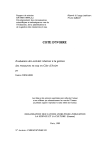
MAINTENANCE INTERVALS
Operation and Maintenance
Manual Excerpt
© 2010 Caterpillar
All Rights Reserved
®
®
SEBU8458-01
November 2009
Operation and
Maintenance
Manual
906H, 907H and 908H Compact Wheel
Loaders
SDH1-Up (906H Machine)
SJM1-Up (907H Machine)
LMD1-Up (908H Machine)
SAFETY.CAT.COM
106
Maintenance Section
Maintenance Interval Schedule
SEBU8458-01
i03704302
Maintenance Interval Schedule
SMCS Code: 7000
Ensure that all safety information, warnings and
instructions are read and understood before any
operation or any maintenance procedures are
performed.
The user is responsible for the performance of
maintenance, including all adjustments, the use of
proper lubricants, fluids, filters, and the replacement
of components due to normal wear and aging. Failure
to adhere to proper maintenance intervals and
procedures may result in diminished performance of
the product and/or accelerated wear of components.
Backup Alarm - Test ............................................ 108
Brake System Fluid Level - Check ....................... 111
Cooling System Coolant Level - Check ............... 117
Engine Oil Level - Check .................................... 126
Fuel System Water Separator - Drain ................. 129
Hydraulic System Oil Level - Check ................... 137
Lift Arm and Cylinder Linkage - Lubricate ........... 138
Quick Coupler - Clean/Inspect ............................ 139
Quick Coupler - Lubricate ................................... 140
Seat Belt - Inspect .............................................. 141
Steering Cylinder Bearings - Lubricate ............... 144
Tilt Cylinder Bearings and Bucket Linkage Bearings Lubricate ........................................................... 144
Tire Inflation - Check ........................................... 145
Wheel Nut Torque - Check .................................. 148
Windows - Clean ................................................. 148
Work Tool - Lubricate .......................................... 149
Work Tool Mounting Bracket - Inspect ................ 149
Use mileage, fuel consumption, service hours, or
calendar time, WHICH EVER OCCURS FIRST,
in order to determine the maintenance intervals.
Products that operate in severe operating conditions
may require more frequent maintenance.
Every 50 Service Hours or Monthly
Note: Before each consecutive interval is performed,
all maintenance from the previous interval must be
performed.
Cooling System Coolant Sample (Level 2) Obtain ................................................................ 118
Note: If Cat HYDO Advanced 10 hydraulic oil is
used, the hydraulic oil change interval is extended
to 3000 hours. S·O·S services may extend the oil
change even longer. Consult your Caterpillar dealer
for details.
Note: After the initial 250 hours the hystat system
needs to be calibrated. A Caterpillar dealer must
perform the calibration. Consult your Caterpillar
dealer for information about the calibration.
Cab Air Filter - Clean/Replace ............................. 114
Initial 250 Service Hours
Every 250 Service Hours
Engine Oil Sample - Obtain ................................ 126
Every 250 Service Hours or Monthly
Engine Air Filter Service Indicator Inspect/Replace ................................................ 124
Every 250 Service Hours or 3 Months
Steering Column Play - Check ............................ 142
When Required
Every 250 Service Hours or 6 Months
Battery or Battery Cable - Inspect/Replace ........ 109
Bucket Cutting Edges - Inspect/Replace ............. 112
Bucket Tips - Inspect/Replace ............................. 113
Cab Air Filter - Clean ........................................... 113
Engine Air Filter Primary Element - Clean/
Replace ............................................................. 122
Engine Air Filter Secondary Element - Replace .. 123
Engine Compartment - Clean ............................. 125
Fuel Tank Water and Sediment - Drain ............... 130
Fuses - Replace .................................................. 131
Hinges - Lubricate ............................................... 134
Oil Filter - Inspect ................................................ 138
Radiator Core - Clean ......................................... 140
Window Washer Reservoir - Fill .......................... 148
Window Wiper - Inspect/Replace ........................ 148
Brake Pads - Check ............................................ 109
Braking System - Test .......................................... 111
Differential and Final Drive Oil Level - Check ..... 121
Transfer Drive (Hydrostatic) Oil Level - Check ... 146
Every 10 Service Hours or Daily
Air Cleaner Dust Valve - Clean/Inspect .............. 108
Articulation Bearings - Lubricate ......................... 108
Initial 500 Service Hours
Differential and Final Drive Oil - Change ............. 119
Engine Valve Lash - Check ................................. 128
Transfer Drive (Hydrostatic) Oil - Change ........... 145
Every 500 Service Hours
Differential and Final Drive Oil Sample - Obtain .. 122
Hydraulic System Oil Sample - Obtain ............... 138
Transfer Drive (Hydrostatic) Oil Sample Obtain ............................................................... 147
SEBU8458-01
Every 500 Service Hours or 3 Months
Cooling System Coolant Sample (Level 1) Obtain ................................................................ 117
Fuel Tank Cap and Strainer - Clean ................... 130
Every 500 Service Hours or 1 Year
Engine Oil and Filter - Change ........................... 127
Fuel System Filter and Water Separator Replace ............................................................. 128
Hydraulic System Oil Filter (Return) - Replace ... 136
Every 1000 Service Hours or 6 Months
Differential and Final Drive Oil - Change ............. 119
Transfer Drive (Hydrostatic) Oil - Change ........... 145
Every 1000 Service Hours or 1 Year
Brake System Fluid - Change .............................. 110
Engine Crankcase Breather (Closed Circuit) Replace ............................................................. 125
Engine Valve Lash - Check ................................. 128
Hydraulic System Oil - Change ........................... 135
Rollover Protective Structure (ROPS) - Inspect .. 141
Every 3000 Service Hours
Hydraulic System Oil (HYDO Advanced 10) Change ............................................................. 134
Steering Column Spline (HMU Steering) Lubricate ........................................................... 143
Every 3000 Service Hours or 2 Years
Cooling System Coolant Extender (ELC) - Add ... 117
Cooling System Water Temperature Regulator Replace .............................................................. 118
Every 3 Years After Date of Installation or
Every 5 Years After Date of Manufacture
Seat Belt - Replace ............................................. 142
Every 6000 Service Hours
Hydraulic System Oil (HYDO Advanced 10) Change ............................................................. 134
Every 6000 Service Hours or 4 Years
Cooling System Coolant (ELC) - Change ............ 115
107
Maintenance Section
Maintenance Interval Schedule
108
Maintenance Section
Air Cleaner Dust Valve - Clean/Inspect
SEBU8458-01
i02957879
Air Cleaner Dust Valve Clean/Inspect
SMCS Code: 1051-571-VL
1. Open the engine hood.
2. The air filter housing is located on the right side of
the engine compartment.
Illustration 99
Illustration 100
g01355727
Illustration 101
g01355731
g01379352
3. Check the dust valve after every ten service hours
or at the end of each day. Actuate the valve by
squeezing the lips of the valve in order to remove
any accumulated debris.
Apply lubricant to the grease fittings for the upper
and lower bearing and for the oscillation bearing.
4. Close the engine hood.
i02699187
Articulation Bearings Lubricate
SMCS Code: 7057-086-BD; 7065-086-BD;
7066-086-BD
Wipe the grease fittings before you lubricate the
grease fittings.
i01390799
Backup Alarm - Test
SMCS Code: 7406-081
The backup alarm is mounted below the radiator in
the engine compartment.
The backup alarm has one sound level. The sound
level is not adjustable.
SEBU8458-01
109
Maintenance Section
Battery or Battery Cable - Inspect/Replace
Turn the engine start switch key to the ON position in
order to perform the test.
4. Perform the necessary repairs. Replace the cable
or the battery, as needed.
Apply the service brake. Move the direction control
switch to the REVERSE position.
5. Disconnect the positive battery cable. Remove the
old battery from the machine.
The backup alarm should immediately sound. The
backup alarm will continue to sound until the direction
control switch is moved to the NEUTRAL position or
to the FORWARD position.
6. Place the new battery in the machine. Connect
the positive battery cable to the battery.
i03704739
Battery or Battery Cable Inspect/Replace
7. Connect the negative battery cable at the battery.
Recycle the Battery
Always recycle a battery. Never discard a battery.
SMCS Code: 1401-040; 1401-510; 1402-040;
1402-510
1. Turn the engine start switch to the OFF position.
Turn all switches to the OFF position.
2. The battery is located under the hood on the right
side of the machine. Open the hood.
Always return used batteries to one of the following
locations:
• A battery supplier
• An authorized battery collection facility
• Recycling facility
i02699193
Brake Pads - Check
SMCS Code: 4267; 4273
Illustration 103
Illustration 102
g01355762
Battery on Right Side
(1) Positive Battery Terminal
(2) Battery Hold Down
(3) Negative Battery Terminal
To avoid personal injury from electrical shock, ensure that the negative battery cable is disconnected first.
3. Disconnect the negative battery cable at the
battery.
g01355884
The brake pads are located behind the front axle on
the drive shaft. Measure the thickness of the brake
pads. If the thickness of either of the two brake pads
is less than 4.00 mm (0.16 inch), replace the brake
pads. Refer to Disassembly and Assembly, “Brake
Caliper - Remove” and Disassembly and Assembly,
“Brake Caliper - Install”.
110
Maintenance Section
Brake System Fluid - Change
SEBU8458-01
i02699194
Brake System Fluid - Change
(If Equipped)
SMCS Code: 4258-044; 7579-044-BRK
Hot oil and components can cause personal injury.
Do not allow hot oil or components to contact
skin.
NOTICE
Care must be taken to ensure that fluids are contained
during performance of inspection, maintenance, testing, adjusting and repair of the product. Be prepared to
collect the fluid with suitable containers before opening any compartment or disassembling any component containing fluids.
Illustration 104
g01355891
Refer to Special Publication, NENG2500, “Caterpillar
Dealer Service Tool Catalog” for tools and supplies
suitable to collect and contain fluids on Caterpillar
products.
3. Remove the lid on the brake fluid reservoir. The
fluid reservoir is located in the compartment in
front of the cab. Add the correct type of brake
fluid to the reservoir. Refer to Operation and
Maintenance Manual, “Lubricant Viscosities Chart”
for the correct fluid.
Dispose of all fluids according to local regulations and
mandates.
4. Open the purge valve.
Note: Brake fluid reservoirs are available only on
standard machines.
Purge valves for the brake system are located on
service brake cylinders . The cylinders are located on
the drive axle. Access the purge valves below the
machine.
1. Park the machine on a hard, level surface. Stop
the engine. Allow the fluid to cool for five minutes.
However, the brake fluid should be warm for this
procedure.
2. Thoroughly clean the outside of the purge valves.
Attach a line to the purge valve. Drain the fluid
from each purge valve into a suitable container.
5. Fully depress the service brake that is being
purged.
6. Close the purge valve.
7. Release the service brake.
8. Repeat Steps 4 through 7 until no air is in the fluid
that drains from the purge valve. Ensure that the
reservoir remains full of fluid.
9. Start the engine. Run the machine for a few
minutes. Check for any leaks. Maintain the fluid
level between the marks on the reservoir.
SEBU8458-01
111
Maintenance Section
Brake System Fluid Level - Check
i02699196
Brake System Fluid Level Check
(If Equipped)
SMCS Code: 4258-535-FLV; 7579-535-BRK
Hot oil and components can cause personal injury.
Do not allow hot oil or components to contact
skin.
NOTICE
Care must be taken to ensure that fluids are contained
during performance of inspection, maintenance, testing, adjusting and repair of the product. Be prepared to
collect the fluid with suitable containers before opening any compartment or disassembling any component containing fluids.
Refer to Special Publication, NENG2500, “Caterpillar
Dealer Service Tool Catalog” for tools and supplies
suitable to collect and contain fluids on Caterpillar
products.
Dispose of all fluids according to local regulations and
mandates.
Note: Brake fluid reservoirs are available only on
standard machines.
1. Park the machine on a hard, level surface.
i03751342
Braking System - Test
SMCS Code: 4011-081; 4267-081
Service Brake Holding Ability Test
Personal injury can result if the machine moves
while testing.
If the machine begins to move during test, reduce
the engine speed immediately and engage the
parking brake.
Check the area around the machine. Make sure
that the machine is clear of personnel and clear of
obstacles.
Make sure that the steering frame lock link is in the
STORED position.
Test the brakes on a dry 25% slope.
Fasten the seat belt before you test the brakes.
The following tests are used to determine if the
service brake is functional. These tests are not
intended to measure the maximum brake holding
effort.
1. Start the engine. Raise the work tool slightly.
2. Apply the service brake. Release the parking
brake.
2. The fluid reservoir is located in the compartment
in front of the cab.
The machine should not move under the following
conditions.
3. Check the fluid level when the engine is stopped.
• The engine is at low idle.
4. Maintain the fluid level between the marks on the
reservoir.
• The bucket is empty.
5. If the fluid level is low, add fluid.
• The machine is warmed up and the machine is
fully stopped.
a. Remove the lid on the brake fluid reservoir.
• The service brake is firmly depressed.
b. Add the correct type of brake fluid to the
reservoir. Refer to Operation and Maintenance
Manual, “Lubricant Viscosities Chart” for the
correct fluid.
If the machine moves, consult your Caterpillar
dealer.
c. Install the lid on the reservoir.
6. Check for any leaks. Maintain the fluid level
between the marks on the reservoir.
3. Engage the parking brake. Lower the work tool to
the ground. Stop the engine.
112
Maintenance Section
Bucket Cutting Edges - Inspect/Replace
NOTICE
If the machine moved while testing the brakes, contact
your Caterpillar dealer. Have the dealer inspect and,
if necessary, repair the service brake before returning
the machine to operation.
Parking Brake Holding Ability Test
Check the area around the machine. Make sure
that the machine is clear of personnel and clear of
obstacles.
Make sure that the steering frame lock link is in the
STORED position.
SEBU8458-01
NOTICE
If the machine moved while testing the brakes, contact
your Caterpillar dealer.
Have the dealer inspect and, if necessary, repair the
parking brakes before returning the machine to operation.
i01743875
Bucket Cutting Edges Inspect/Replace
SMCS Code: 6801-040; 6801-510
Test the brakes on a dry 20% slope.
Note: The test condition is different from the Service
Brake test.
Fasten the seat belt before you test the brakes.
The following tests are used to determine if the
parking brake is functional. These tests are not
intended to measure the maximum brake holding
effort.
Personal injury or death can result from bucket
falling.
Block the bucket before changing bucket cutting
edges.
1. Lower the lift arms fully. Tilt back the bucket so
that the bucket cutting edge is accessible.
1. Start the engine. Raise the work tool slightly.
2. Place blocks under the raised edge of the bucket.
2. Engage the parking brake. Release the service
brake gradually.
3. Remove the bolts. Remove the cutting edge and
the end bits.
Note: The parking brake indicator light should
come on. The parking brake light should flash if the
machine is in gear.
4. Clean the contact surfaces.
The machine should not move under the following
conditions.
5. Use the opposite side of the cutting edge, if this
side is not worn.
6. Install a new cutting edge, if both edges are worn.
• The engine is at low idle.
7. Install the bolts.
• The bucket is empty.
8. Remove the blocks that are under the bucket.
• The machine is warmed up and the machine is
9. After a few hours of operation, check the bolts for
proper torque.
fully stopped.
• The parking brake is pulled up firmly.
If the machine moves, consult your Caterpillar
dealer.
If the machine begins to move, reduce the engine
speed immediately and apply the service brake
pedal.
3. Lower the bucket to the ground. Stop the engine.
SEBU8458-01
113
Maintenance Section
Bucket Tips - Inspect/Replace
i01764331
i02708467
Bucket Tips - Inspect/Replace
Cab Air Filter - Clean
SMCS Code: 6805-040; 6805-510
SMCS Code: 7342-070
Clean Internal Filter Element
Personal injury or death can result from bucket
falling.
Block the bucket before changing bucket cutting
edges.
1. Lower the lift arms fully. Tilt back the bucket so
that the bucket tips are accessible.
2. Place blocks under the raised edge of the bucket.
3. Remove the mounting bolts. Remove the bucket
tips.
4. Clean the mounting surface.
5. Replace the bucket tips.
6. Install the bolts.
7. Remove the blocks that are under the bucket.
8. After a few hours of operation, check the bolts for
proper torque.
Illustration 105
g01359738
(1) Screws
(2) Internal Filter Element
The internal filter element is located in the cab on the
left side. There may be a cover panel over the filter. If
your machine has a storage box in the cab, the filter
is behind the storage box.
1. Remove the cover panel or remove the storage
box.
2. Remove the 2 screws that hold the filter in place.
3. Remove the filter element. Clean the filter element
with compressed air. You can also wash the filter
elements with a solution of warm water and of a
nonsudsing household detergent.
Do not wash the filter element while the filter
element is installed on the machine.
Replace the filter element if the filter element is
damaged.
4. Rinse the filter element in clean water. Air dry the
filter element thoroughly.
5. Install the filter element and replace the screws.
6. Install the cover panel or install the storage box.
114
Maintenance Section
Cab Air Filter - Clean/Replace
SEBU8458-01
i02699198
Cab Air Filter - Clean/Replace
SMCS Code: 7342-070; 7342-510
Note: Clean the filter elements more often in dusty
conditions. If there is a noticeable reduction in the air
flow from the air vents, check the filter elements.
Clean External Filter Element
Illustration 107
g01355653
Thumb screw for the access panel
Note that the engine hood is removed for clarity.
2. Remove the access cover (1).
Illustration 106
g01355651
(1) Access Cover
(2) Access Door
1. Open the access door (2) on the left side of the
machine.
Illustration 108
g01355920
3. Loosen the 2 top thumb screws (3) that hold the
air duct (4). Remove the bottom thumb screw (5).
SEBU8458-01
115
Maintenance Section
Cooling System Coolant (ELC) - Change
NOTICE
Mixing ELC with other products will reduce the effectiveness of the coolant.
This could result in damage to cooling system components.
If Caterpillar products are not available and commercial products must be used, make sure they
have passed the Caterpillar EC-1 specification for
pre-mixed or concentrate coolants and Caterpillar
Extender.
Note: The machine was shipped from the factory with
Extended Life Coolant (ELC) in the cooling system.
Illustration 109
g01355951
4. Remove the filter element. Clean the filter element
with compressed air.
5. Install the filter element and replace the thumb
screw.
For information about the addition of Extender to your
cooling system, see the Operation and Maintenance
Manual, “Cooling System Coolant (ELC) Extender Add” or consult your Caterpillar dealer.
Drain the coolant whenever the coolant is dirty or
whenever the coolant is foaming.
Allow the machine to cool before you change the
coolant.
1. Open the engine hood. Refer to Operation and
Maintenance Manual, “Access Doors and Covers”.
6. Tighten all of the thumb screws.
7. Install the access panel.
Note: The coolant tank is located on the right side of
the engine compartment.
8. Close the access door.
i02754409
Cooling System Coolant (ELC)
- Change
SMCS Code: 1395-044-NL
Pressurized system: Hot coolant can cause serious burn. To open cap, stop engine, wait until radiator is cool. Then loosen cap slowly to relieve
the pressure.
Illustration 110
g01357729
2. Slowly loosen the cap (1) in order to relieve
system pressure. Remove the cap.
116
Maintenance Section
Cooling System Coolant (ELC) - Change
Illustration 111
SEBU8458-01
g01357744
3. Locate the drain for the engine coolant on the side
of the engine. Attach a drain hose to the drain
valve that is shown in illustration 111. Open the
drain and allow the coolant to drain into a suitable
container.
Illustration 113
g01380076
5. Open the drain and allow the coolant to drain from
the radiator into a suitable container.
6. Close the drain.
7. Replace the access panel.
8. Replace the thermostat. See Operation and
Maintenance Manual, “Cooling System Water
Temperature Regulator - Replace” for the process
for replacing the thermostat.
9. Add the coolant solution directly to the coolant
tank. Refer to Operation and Maintenance
Manual, “Capacities - (Refill)”. Refer to Special
Publication, SEBU6250, “Caterpillar Machine
Fluids Recommendations”.
Note: Premix the coolant solution before filling
the cooling system. The coolant solution should
contain 50 percent coolant and 50 percent
distilled water.
Illustration 112
g01359660
4. Remove the access panel under the rear of the
machine.
Note: Add the coolant solution at a maximum rate
of five liters per minute. This will reduce the chance
of trapping air inside the engine block. A large amount
of trapped air can cause localized heating to occur
upon start-up. Localized heating may result in engine
damage, which may lead to failure of the engine.
10. Start the engine. Run the engine without the
radiator cap for 30 seconds. Stop the engine.
Allow the engine to sit for 1 minute. Check the
coolant level. If necessary, add coolant.
11. Check the coolant level in the coolant tank.
Maintain the coolant level to the top mark on the
tank.
SEBU8458-01
117
Maintenance Section
Cooling System Coolant Extender (ELC) - Add
12. Stop the engine. Inspect the cap for the coolant
tank and the gasket. Replace the cap if the cap or
the gasket is damaged. Install the cap.
Open the engine hood. The coolant tank is located
on the right side above the battery.
13. Close the engine hood.
i01389522
Cooling System Coolant
Extender (ELC) - Add
SMCS Code: 1352-544-NL
Pressurized system: Hot coolant can cause serious burn. To open cap, stop engine, wait until radiator is cool. Then loose the cap slowly to relieve
the pressure.
When a Caterpillar Extended Life Coolant is
used, an extender must be added to the cooling
system. See the Operation and Maintenance
Manual, “Maintenance Interval Schedule” for the
proper service interval. The amount of extender is
determined by the cooling system capacity.
Table 29
RECOMMENDED AMOUNT OF EXTENDER BY
COOLING SYSTEM CAPACITY
Cooling System Capacity
Recommended Amount
of Extender
22 to 30 L (6 to 8 US gal)
0.57 L (.60 qt)
30 to 38 L (8 to 10 US gal)
0.71 L (.75 qt)
38 to 49 L (10 to 13 US gal)
0.95 L (.95 qt)
49 to 64 L (13 to 17 US gal)
1.18 L (1.25 qt)
For additional information on the addition of extender,
see Operation and Maintenance Manual, SEBU6250,
“Cooling System Specifications” or consult your
Caterpillar dealer.
i02699202
Cooling System Coolant Level
- Check
Illustration 114
g01357729
1. Remove the cap (1) from the coolant tank.
2. Maintain the coolant level between the marks on
the side of the tank, when the cooling system is
cool. If you need to add coolant daily, check the
cooling system for leaks.
3. Replace the cap if the seal is damaged.
4. Install the cap on the tank.
i02699199
Cooling System Coolant
Sample (Level 1) - Obtain
SMCS Code: 1395-008; 7542
NOTICE
Always use a designated pump for oil sampling, and
use a separate designated pump for coolant sampling.
Using the same pump for both types of samples may
contaminate the samples that are being drawn. This
contaminate may cause a false analysis and an incorrect interpretation that could lead to concerns by both
dealers and customers.
SMCS Code: 1350-535-FLV
Note: Level 1 results may indicate a need for Level
2 analysis.
Pressurized system: Hot coolant can cause serious burn. To open cap, stop engine, wait until radiator is cool. Then loosen cap slowly to relieve
the pressure.
118
Maintenance Section
Cooling System Coolant Sample (Level 2) - Obtain
Illustration 115
g01357744
Coolant Drain Valve
SEBU8458-01
Illustration 116
g01357744
1. Open the engine hood.
1. Open the engine hood.
2. Open the coolant drain valve that is located on the
side of the engine in order to sample the coolant.
2. Open the coolant drain valve that is located on the
side of the engine in order to sample the coolant.
Submit the sample for Level 2 analysis.
3. Submit the sample for Level 1 analysis.
i02998149
Cooling System Coolant
Sample (Level 2) - Obtain
Cooling System Water
Temperature Regulator Replace
SMCS Code: 1395-008; 7542
SMCS Code: 1355-510; 1393-010
NOTICE
Always use a designated pump for oil sampling, and
use a separate designated pump for coolant sampling.
Using the same pump for both types of samples may
contaminate the samples that are being drawn. This
contaminate may cause a false analysis and an incorrect interpretation that could lead to concerns by both
dealers and customers.
Failure to replace the engine's thermostat on a
regularly scheduled basis could cause severe engine
damage.
i02699201
The thermostat should be replaced after the cooling
system has been cleaned. Replace the thermostat
while the cooling system is completely drained or
while the coolant is drained to a level that is below
the thermostat housing.
Caterpillar engines incorporate a shunt design
cooling system. It is mandatory to always operate the
engine with a thermostat.
SEBU8458-01
119
Maintenance Section
Differential and Final Drive Oil - Change
Differential Oil
Illustration 117
g01520307
1. Loosen the hose clamp and remove the hose from
the thermostat housing assembly.
2. Remove the bolts from the assembly and remove
the assembly.
Illustration 118
g01357818
Front Differential
(1) Level/Fill Plug
(2) Drain Plug
3. Remove the gasket, the thermostat, and the seal
from the assembly.
4. Install a new seal in the assembly. Install a new
thermostat and a new gasket. Install the assembly.
5. Install the hose. Tighten the hose clamp.
6. Refill the cooling system. See Operation and
Maintenance Manual, SEBU6250, “Cooling
System Specifications” and Operation and
Maintenance Manual, “Refill Capacities”.
i02699128
Differential and Final Drive Oil
- Change
SMCS Code: 3278-044; 4050-044
Illustration 119
g01357819
Rear Differential
Wipe the covers and surfaces around openings
before you check the oil. Wipe the covers and
surfaces around openings before you add oil.
(1) Level/Fill Plug
(2) Drain Plug
1. Remove the drain plugs (2) from both differentials.
Allow the oil to drain into a suitable container.
2. Clean the drain plugs and reinstall the drain plugs.
3. Remove the differential level/fill plug (1) from both
differentials.
120
Maintenance Section
Differential and Final Drive Oil - Change
SEBU8458-01
4. Fill the differentials with oil. See Operation and
Maintenance Manual, “Lubricant Viscosities”
and Operation and Maintenance Manual, “Refill
Capacities”.
5. Maintain the oil level at the bottom of the threads
for the plug.
6. Clean the differential level/fill plugs and install the
plugs for each differential. Operate the machine
for a few minutes in order to allow the oil to
flow completely through the axles. Remove the
differential level/fill plugs and recheck the oil level.
Add oil, if necessary. Install the differential level/fill
plugs for each differential.
Oil for the Wheel
Illustration 121
g01357831
Wheel in the position for filling
Note: Work on one wheel at a time.
1. Move the machine so that the plug on the wheel is
on the bottom of the wheel.
2. Remove the drain plug from the wheel. Allow the
oil to drain into a suitable container.
3. Move the machine so that the plug on the wheel is
in the horizontal position.
Illustration 120
Wheel in the position for draining
g01357829
4. Fill the wheel with oil. See Operation and
Maintenance Manual, “Lubricant Viscosities”
and Operation and Maintenance Manual, “Refill
Capacities” for information about the oil.
5. Maintain the oil level at the bottom of the threads
for the plug.
6. Clean the plug and install the plug. Operate the
machine for a few minutes in order to allow the
oil to flow completely through the axles. Remove
the plug and recheck the oil level. Add oil, if
necessary. Install the plug.
7. Repeat steps 1 through 6 for each wheel.
SEBU8458-01
121
Maintenance Section
Differential and Final Drive Oil Level - Check
i02699138
Differential and Final Drive Oil
Level - Check
SMCS Code: 3278-535-FLV; 4050-535-FLV
1. Remove the differential level/fill plugs (1) for the
front axle and the rear axle.
2. The oil level should be at the bottom of the threads
for the plug.
3. Add oil, if necessary.
Differential
4. Clean the plugs and install the plugs.
Wheels
Illustration 122
g01357818
Front Differential
(1) Level/Fill Plug
(2) Drain Plug
Illustration 124
g01357831
Wheel in the position for checking
Note: Work on one wheel at a time.
1. Move the machine so that the plug on the wheel is
in the horizontal position.
2. Remove the level/fill plugs for the wheel.
3. The oil level should be at the bottom of the threads
for the plug.
4. Maintain the oil level at the bottom of the threads
for the plug.
5. Add oil, if necessary.
6. Clean the plug and install the plug.
7. Repeat steps 1 through 6 for each wheel.
Illustration 123
Rear Differential
(1) Level/Fill Plug
(2) Drain Plug
g01357819
122
Maintenance Section
Differential and Final Drive Oil Sample - Obtain
SEBU8458-01
i02699139
Differential and Final Drive Oil
Sample - Obtain
SMCS Code: 3278-008; 4050-008; 4070-008; 7542
NOTICE
Caterpillar recommends certified air filter cleaning services that are available at Caterpillar dealers. The
Caterpillar cleaning process uses proven procedures
to assure consistent quality and sufficient filter life.
Observe the following guidelines if you attempt to
clean the filter element:
Hot oil and components can cause personal injury.
Do not tap or strike the filter element in order to remove dust.
Do not allow hot oil or components to contact
skin.
Do not wash the filter element.
1. Operate the machine for a few minutes before you
obtain the fluid sample. This will thoroughly mix
the fluid for a more accurate sample.
Use low pressure compressed air in order to remove
the dust from the filter element. Air pressure must not
exceed 207 kPa (30 psi). Direct the air flow up the
pleats and down the pleats from the inside of the filter
element. Take extreme care in order to avoid damage
to the pleats.
2. Obtaining a sample will require a vacuum pump or
an equivalent. Withdraw the oil through the filler
opening.
Reference: For more information, refer to
Special Publication, SEBU6250, “Caterpillar
Machine Fluids Recommendations” and Special
Publication, PEHP6001, “How To Take A Good
Oil Sample”.
Do not use air filters with damaged pleats, gaskets, or
seals. Dirt entering the engine will cause damage to
engine components.
i02699204
Engine Air Filter Primary
Element - Clean/Replace
SMCS Code: 1054-070-PY; 1054-510-PY
NOTICE
Service the air cleaner only with the engine stopped.
Engine damage could result if the air cleaner is serviced while the engine is running.
Service the air cleaner filter element when the yellow
piston on the engine air filter service indicator enters
the red zone. Refer to Operation and Maintenance
Manual, “Engine Air Filter Service Indicator - Inspect”.
Illustration 125
Location of the engine air filter
(1) Engine Air Filter Service Indicator
(2) Engine Air Filter
1. Open the engine hood.
g01357913
SEBU8458-01
123
Maintenance Section
Engine Air Filter Secondary Element - Replace
i02699205
Engine Air Filter Secondary
Element - Replace
SMCS Code: 1054-510-SE
NOTICE
Always replace the secondary filter element. Never
attempt to reuse it by cleaning.
The secondary filter element should be replaced at the
time the primary element is serviced for the third time.
The secondary filter element should also be replaced
if the yellow piston in the filter element indicator enters the red zone after installation of a clean primary
element, or if the exhaust smoke is still black.
Illustration 126
g01379338
2. Release the 3 clips on the air cleaner housing
cover. Remove the air cleaner housing cover.
Illustration 127
g01379340
3. Remove the primary filter element.
4. Install a clean air filter element. Install the air
cleaner housing cover and fasten the clips.
5. Reset the engine air filter service indicator.
If the yellow piston in the indicator remains in the red
zone, replace the secondary element.
NOTICE
Service the air cleaner only with the engine stopped.
Engine damage could result if the air cleaner is serviced while the engine is running.
Illustration 128
g01379338
1. Release the 3 clips on the air cleaner housing
cover. Remove the air cleaner housing cover.
124
Maintenance Section
Engine Air Filter Service Indicator - Inspect/Replace
SEBU8458-01
8. Install the air cleaner housing cover and install
the clip.
9. Reset the engine air filter service indicator.
i02699207
Engine Air Filter Service
Indicator - Inspect/Replace
SMCS Code: 7452-040; 7452-510
Illustration 129
g01379340
2. Remove the primary filter element.
Illustration 131
g01357913
Location of the engine air filter
(1) Engine Air Filter Service Indicator
(2) Engine Air Filter
1. Mount the machine.
2. Fasten the seat belt and start the engine.
3. Run the engine at high idle.
4. Stop the engine.
Illustration 130
g01379368
3. Remove the secondary filter element.
4. Cover the air inlet opening. Clean the inside of
the air cleaner housing.
5. Open the engine hood.
6. Inspect the indicator. If the yellow piston in the
indicator enters the red zone, service the air
cleaner.
5. Inspect the gasket between the air inlet pipe and
the air cleaner housing. Replace the gasket if the
gasket is damaged.
Note: See Operation and Maintenance Manual,
“Engine Air Filter Primary Element - Clean/Replace”.
See Operation and Maintenance Manual, “Engine Air
Filter Secondary Element - Replace”.
6. Uncover the air inlet opening. Install a new
secondary element.
7. Reset the indicator.
7. Install the primary element.
SEBU8458-01
125
Maintenance Section
Engine Compartment - Clean
Note: To check the condition of the service indicator,
try resetting the service indicator. This should require
less than three pushes of the reset button. Next,
check the movement of the yellow piston in the
service indicator. Start the engine and accelerate
the engine to high idle for a few seconds. After
the governor control pedal is released, the yellow
piston should remain at the highest position that
was achieved during acceleration. If either of these
conditions are not met, replace the service indicator.
i02699208
Engine Crankcase Breather
(Closed Circuit) - Replace
SMCS Code: 1317-510
i02708486
Engine Compartment - Clean
SMCS Code: 1000-070-CPA
Inspect the engine compartment for dirt buildup or
debris. Remove any dirt or debris from the engine
compartment.
1. Open the engine hood. Refer to Operation and
Maintenance Manual, “Access Doors and Covers”.
Illustration 133
g01357934
The engine crankcase breather is located inside the
engine compartment.
1. Loosen the three hose clamps and remove hoses
(1), (2), and (3) from the breather.
2. Remove two bolts (4) and washers from the
breather.
Illustration 132
g01359660
3. Remove breather (5) from the bracket.
2. Remove any debris or dirt from the engine
compartment. If necessary, remove the belly plate
in order to clean out the engine compartment. The
belly plate is located under the rear of the machine
on the left side.
4. Inspect the hoses for damage. If the hoses are
worn or damaged, replace the hoses.
Note: Use care when you clean the engine
compartment. Damage to the machine may occur.
6. Install hoses (3), (2), and (1) to the breather and
tighten the hoses.
3. Install the belly plate. Close the engine hood.
7. Close the engine hood.
5. Replace new breather (5) with washers and two
bolts (4).
126
Maintenance Section
Engine Oil Level - Check
SEBU8458-01
i02998164
Engine Oil Level - Check
SMCS Code: 1348-535-FLV
NOTICE
Do not overfill the crankcase. Engine damage can result.
1. Open the engine hood.
Illustration 135
g01277108
(1) Oil level add mark
(2) Full mark
2. Maintain the oil level between the mark (1) and
the mark (2) on the dipstick.
Note: After ten minutes, check the oil level on the
dipstick.
3. If necessary, remove the oil filler cap and add oil.
4. Clean the oil filler cap and install the oil filler cap.
5. Close the engine hood.
i02998169
Engine Oil Sample - Obtain
SMCS Code: 1348-008; 7542
Open the engine hood.
Illustration 134
(1)
(2)
(3)
(4)
(5)
Oil
Oil
Oil
Oil
Oil
Filler Cap
Dipstick
Filter
Drain Valve
Sample Port
g01520314
SEBU8458-01
127
Maintenance Section
Engine Oil and Filter - Change
Refer to the results of the S·O·S oil analysis in order
to determine if the engine oil change interval should
be decreased. Consult your Caterpillar dealer for
detailed information regarding the optimum engine
oil change interval.
1. Open the engine hood.
Illustration 136
(1)
(2)
(3)
(4)
(5)
Oil
Oil
Oil
Oil
Oil
g01520314
Filler Cap
Dipstick
Filter
Drain Valve
Sample Port
The sampling port for the engine oil is located on the
right side of the engine block next to the oil filter base.
i02998175
Engine Oil and Filter - Change
SMCS Code: 1308-510; 1348-044
The normal engine oil change interval is every 500
service hours or one year. If the engine is operated
under severe conditions or if the oil is not Caterpillar
oil, change the oil after every 250 service hours
or after six months. Severe conditions include the
following factors: high temperatures, continuous high
loads, and extremely dusty conditions.
Illustration 137
(1)
(2)
(3)
(4)
(5)
Oil
Oil
Oil
Oil
Oil
g01520314
Filler Cap
Dipstick
Filter
Drain Valve
Sample Port
2. Open the crankcase drain valve and drain the oil
into a suitable container.
3. Close the crankcase drain valve.
4. Remove the filter element with a strap type
wrench. Refer to Operation and Maintenance
Manual, “Oil Filter - Inspect”.
5. Clean the filter mounting base with a clean cloth.
Make sure that the old filter gasket has been
removed.
128
Maintenance Section
Engine Valve Lash - Check
SEBU8458-01
6. Apply a thin film of clean engine oil to the sealing
surface of the new filter element.
7. Install a new engine oil filter hand tight until the
seal of the engine oil filter contacts the base. Note
the position of the index marks on the filter in
relation to a fixed point on the filter base.
Note: There are rotation index marks on the engine
oil filter that are spaced 90 degrees or 1/4 of a turn
away from each other. When you tighten the engine
oil filter, use the rotation index marks as a guide.
i03005669
Fuel System Filter and Water
Separator - Replace
SMCS Code: 1261-510; 1263-510
The fuel system filter/water separator element is
located in the engine compartment on the left side.
1. Open the engine access door.
8. Tighten the filter according to the instructions
that are printed on the filter. Use the index marks
as a guide. For non-Caterpillar filters, use the
instructions that are provided with the filter.
Note: You may need to use a Caterpillar strap
wrench, or another suitable tool, in order to turn
the filter to the amount that is required for final
installation. Make sure that the installation tool does
not damage the filter.
9. Wipe the area around the oil filler cap. Remove the
oil filler cap. Fill the crankcase with new oil. Refer
to Operation and Maintenance Manual, “Lubricant
Viscosities” and Operation and Maintenance
Manual, “Refill Capacities”. Clean the oil filler cap
and install the oil filler cap.
10. Start the engine and allow the oil to warm. Check
for leaks.
Note: After you stop the engine, you must wait for ten
minutes before you check the oil level. This is done
in order to allow the oil to drain back into the oil pan.
11. Stop the engine and wait for ten minutes in order
to allow the oil to drain into the oil pan. Maintain
the oil level in the crosshatched region of the
engine oil dipstick. Add oil, if necessary.
12. Close the engine hood.
Illustration 138
(1)
(2)
(3)
(4)
(5)
(6)
g01355125
Electric fuel priming pump
Fuel filter base
Quick release collar
Fuel filter
Sediment bowl
Drain valve for fuel filter
i00664189
Engine Valve Lash - Check
2. Open the drain on the water separator bowl. Allow
the water and fuel to drain into a suitable container.
SMCS Code: 1105-025
3. Support the water separator element and rotate
the locking ring counterclockwise. Remove the
locking ring.
Refer to the Service Manual for the complete
adjustment procedure for the engine valve lash.
A qualified mechanic should adjust the engine valve
lash and the fuel injector timing because special tools
and training are required.
4. Remove the water separator bowl from the bottom
of the fuel filter/water separator element.
Note: The water separator bowl is reusable. Do not
discard the water separator bowl.
5. Inspect the O-ring seal of the water separator bowl
for damage. Replace the O-ring seal, if necessary.
SEBU8458-01
6. Lubricate the O-ring seal with clean diesel fuel or
lubricate the O-ring seal with motor oil. Place the
seal in the water separator bowl.
7. Spin the water separator bowl onto the new
filter element by hand until the fuel filter/water
separator is snug. Do not use tools to tighten the
fuel filter/water separator element to the bowl.
129
Maintenance Section
Fuel System Water Separator - Drain
i03005672
Fuel System Water Separator
- Drain
SMCS Code: 1263-543
8. Clean the filter mounting base.
9. Install the new element. Rotate the locking ring
clockwise in order to fasten the filter to the
mounting base.
10. In order to activate the electric fuel priming pump,
turn the ignition switch to the START position
and release the ignition switch. This process will
activate the relay for the electric fuel priming
pump which allows power to reach the electric fuel
priming pump. The electrically operated fuel pump
will fill the water separator element with fuel.
Illustration 139
(1)
(2)
(3)
(4)
(5)
(6)
g01355125
Electric fuel priming pump
Fuel filter base
Quick release collar
Fuel filter
Sediment bowl
Drain valve for fuel filter
1. Open the engine hood.
2. Pull the drain hose outside the engine
compartment.
3. Loosen the drain valve on the bottom of the water
separator. Allow the water and the sediment to
drain into a suitable container.
4. Tighten the drain valve and put the drain hose
inside the engine compartment.
5. Close the engine hood.
130
Maintenance Section
Fuel Tank Cap and Strainer - Clean
SEBU8458-01
i02724242
Fuel Tank Cap and Strainer Clean
SMCS Code: 1273-070-Z2; 1273-070-STR
3. Remove the strainer that is located in the filler
opening.
4. Wash the strainer and the fuel tank cap in a clean,
nonflammable solvent.
5. Install the strainer into the filler opening.
6. Install the fuel tank cap. Close the engine access
door.
i02699147
Fuel Tank Water and Sediment
- Drain
SMCS Code: 1273-543-M&S
Release the pressure in the fuel tank by loosening
the fuel tank cap.
The fuel tank drain valve is located in the center on
the left side underneath the machine.
Illustration 140
g01366657
The fuel cap is located in the center on the left side
of the machine.
Illustration 142
g01358191
Remove the cover.
Open the fuel tank drain valve. Allow the water and
sediment to drain into a suitable container. Close the
fuel tank drain valve.
Illustration 141
g01366659
1. Lift the lever (1) and turn the lever counterclockwise
until the lever stops. Remove the cap (2).
2. Inspect the seal for damage. Replace the seal, if
necessary.
Replace the cover.
SEBU8458-01
131
Maintenance Section
Fuses - Replace
i02699211
Fuses - Replace
SMCS Code: 1417-510
Fuses
Fuses – Fuses protect the electrical system from
damage that is caused by overloaded circuits.
Replace the fuse if the element separates. If the
element of a new fuse separates, check the circuit.
Repair the circuit, if necessary.
NOTICE
Replace the fuses with the same type and size only.
Otherwise, electrical damage can result.
If it is necessary to replace fuses frequently, an electrical problem may exist. Contact your Caterpillar dealer
Illustration 144
g01356829
The fuse panel is located on the right side of the cab.
In order to access the fuse panel, you must open the
right side door.
Illustration 143
g01356828
132
Maintenance Section
Fuses - Replace
SEBU8458-01
7 – Work Tool Circuit (15 Amp)
8 – Rear Wiper and Washer (10 Amp)
9 – Air Suspension Seat (15 Amp)
10 – Fuel Shutoff (15 Amp)
11 – Rear Window Defroster (20 Amp)
12 – Rear Work Lights (10 Amp)
13 – Air Conditioner (15 Amp)
14 – Left Tail Light (10 Amp)
Illustration 145
g01356830
15 – Right Tail Light (10 Amp)
1 – Ride Control (10 Amp)
16 – Implement Detent (10 Amp)
2 – Reverse Light (10 Amp)
17 – High Beam Lights (15 Amp)
3 – Differential Lock (10 Amp)
18 – Directional Signal Lights (10 Amp)
4 – Front Wiper and Washer (15 Amp)
19 – Front Work Lights (10 Amp)
5 – ECM (15 Amp)
20 – Radio (5 Amp)
6 – Electronic Display (10 Amp)
SEBU8458-01
21 – HVAC Blower Fan (20 Amp)
133
Maintenance Section
Fuses - Replace
Relays
22 – Heated Seat (5 Amp)
23 – Beacon (10 Amp)
24 – Ignition Switch (10 Amp)
25 – Electrical Power (10 Amp)
26 – Hazard Lights (10 Amp)
27 – Lights (10 Amp)
Illustration 146
28 – Starting Aid (10 Amp)
32 – Implement Detent
29 – Brake Lights (10 Amp)
33 – Ride Control
30 – Electrical Power (10 Amp)
34 – Clutch for the Air Conditioner
Compressor
31 – Horn (10 Amp)
35 – Hydraulic
36 – Hydraulic
37 – Differential Lock
38 – Rear Window Defroster
g01356831
134
Maintenance Section
Hinges - Lubricate
SEBU8458-01
i03751352
39 – Reverse Light
Hydraulic System Oil (HYDO
Advanced 10) - Change
40 – Fuel Pump
SMCS Code: 5095-044
Cat HYDO Advanced 10 is the preferred oil for use in
most Caterpillar machine hydraulic and hydrostatic
transmission systems when ambient temperature
is between −20 °C (−4 °F) and 50 °C (122 °F). Cat
HYDO Advanced 10 has an SAE viscosity grade of
10W. Cat HYDO Advanced 10 has a 50% increase
in the standard oil drain interval (up to 3000 hours)
for machine hydraulic systems over second and third
choice oils when you follow the maintenance interval
schedule for oil filter changes and for oil sampling that
is stated in the Operation and Maintenance Manual.
6000 hour oil drain intervals are possible when using
S·O·S Services oil analysis. When you switch to Cat
HYDO Advanced 10, cross contamination with the
previous oil should be kept to less than 10%. Consult
your Cat dealer for details about the benefits from
the improved performance designed into Cat HYDO
Advanced 10.
41 – Intermittent Windshield Wiper
42 – Intermittent Windshield Wiper
Main Fuses
Operate the machine for a few minutes in order to
warm the hydraulic system oil.
The machine should be on level ground. Lower the
bucket to the ground and apply slight downward
pressure. Engage the parking brake and stop the
engine.
Illustration 147
g01357092
(43) 80 Amp Fuse
(44) 60 Amp Fuse
There are 2 main fuses in the engine compartment
on the right side under the battery. If the element of
either one of these fuses is separated, investigate
the cause before operating the machine.
i01416931
Hinges - Lubricate
SMCS Code: 7000-086-HNG
Illustration 148
Use dry film lubricant for the following applications: all
moving door latches, hinges, door locks, lock for the
hood, hinges for the hood, and throttle pedal linkage.
(1)
(2)
(3)
(4)
Filler Cap
Hydraulic Tank
Upper Sight Gauge
Lower Sight Gauge
1. Open the engine hood.
g01358251
SEBU8458-01
135
Maintenance Section
Hydraulic System Oil - Change
2. Remove the hydraulic tank filler cap.
i02699149
3. The hydraulic tank drain plug is located on the
bottom of the hydraulic tank on the underside of
the machine. Remove the drain plug and allow the
hydraulic oil to drain into a suitable container.
4. Install the drain plug.
Hydraulic System Oil - Change
SMCS Code: 5095-044
Operate the machine for a few minutes in order to
warm the hydraulic system oil.
The machine should be on level ground. Lower the
bucket to the ground and apply slight downward
pressure. Engage the parking brake and stop the
engine.
Illustration 149
g01358262
Hydraulic Oil Filter
5. Change the hydraulic system filter. Refer to
Operation and Maintenance Manual, “Hydraulic
System Oil Filter (Return) - Change”.
6. Fill the hydraulic system oil tank with hydraulic
oil. Refer to Operation and Maintenance Manual,
“Lubricant Viscosities” and Operation and
Maintenance Manual, “Refill Capacities”.
Note: Observe the sight gauges for the hydraulic oil
level as you fill the hydraulic system oil tank. Do not
overfill the tank.
7. The sight gauges for the hydraulic oil level are
located on the side of the tank below the filler cap.
Maintain the hydraulic oil level in the center of the
top sight gauge. Add oil, if necessary.
Note: The oil must be free of bubbles. If bubbles are
present in the oil, air is entering the hydraulic system.
Inspect the suction hoses and hose clamps.
8. Inspect the gasket on the hydraulic tank filler cap
for damage. Replace the gasket, if necessary.
9. Install the hydraulic tank filler cap.
10. Close the engine hood.
Illustration 150
(1)
(2)
(3)
(4)
g01358251
Filler Cap
Hydraulic Tank
Upper Sight Gauge
Lower Sight Gauge
1. Open the engine hood.
2. Remove the hydraulic tank filler cap.
3. The hydraulic tank drain plug is located on the
bottom of the hydraulic tank on the underside of
the machine. Remove the drain plug and allow the
hydraulic oil to drain into a suitable container.
4. Install the drain plug.
136
Maintenance Section
Hydraulic System Oil Filter (Return) - Replace
SEBU8458-01
i02699150
Hydraulic System Oil Filter
(Return) - Replace
SMCS Code: 5068-510-RJ
1. Open the engine hood.
2. Remove the hydraulic tank filler cap.
Illustration 151
g01358262
Hydraulic Oil Filter
5. Change the hydraulic system filter. Refer to
Operation and Maintenance Manual, “Hydraulic
System Oil Filter (Return) - Change”.
6. Fill the hydraulic system oil tank with hydraulic
oil. Refer to Operation and Maintenance Manual,
“Lubricant Viscosities” and Operation and
Maintenance Manual, “Refill Capacities”.
Note: Observe the sight gauges for the hydraulic oil
level as you fill the hydraulic system oil tank. Do not
overfill the tank.
7. The sight gauges for the hydraulic oil level are
located on the side of the tank below the filler cap.
Maintain the hydraulic oil level in the center of the
top sight gauge. Add oil, if necessary.
Note: The oil must be free of bubbles. If bubbles are
present in the oil, air is entering the hydraulic system.
Inspect the suction hoses and hose clamps.
8. Inspect the gasket on the hydraulic tank filler cap
for damage. Replace the gasket, if necessary.
9. Install the hydraulic tank filler cap.
10. Close the engine hood.
Illustration 152
g01358262
3. The hydraulic oil filter is located in the engine
compartment.
4. Remove the filter element with a strap type
wrench.
5. Clean the filter element mounting base. Remove
any part of the filter element gasket that remains
on the filter element base.
6. Apply a light coat of oil to the gasket of the new
filter element.
7. Install a new filter hand tight until the seal of the
filter contacts the base. Note the position of the
index marks on the filter in relation to a fixed point
on the filter base.
Note: There are rotation index marks on the filter
that are spaced 90 degrees or 1/4 of a turn away
from each other. When you tighten the filter, use the
rotation index marks as a guide.
8. Tighten the filter according to the instructions
that are printed on the filter. Use the index marks
as a guide. For non-Caterpillar filters, use the
instructions that are provided with the filter.
SEBU8458-01
137
Maintenance Section
Hydraulic System Oil Level - Check
Note: You may need to use a Caterpillar strap
wrench, or another suitable tool, in order to turn
the filter to the amount that is required for final
installation. Make sure that the installation tool does
not damage the filter.
9. Maintain the hydraulic oil level at the middle of the
top sight gauge. Add oil, if necessary.
10. inspect the gasket on the hydraulic tank filler cap
for damage. Replace the gasket, if necessary.
11. Install the hydraulic tank filler cap.
12. Close the engine hood.
i02699152
Hydraulic System Oil Level Check
SMCS Code: 5095-535-FLV
Note: Check the hydraulic system oil level with the
machine on a level surface.
1. Lower the work tool to the ground. Turn off the
engine.
2. Open the engine hood.
3. Wait for about five minutes before checking
the level of the hydraulic oil. The hydraulic
tank is located on the right side of the engine
compartment.
Illustration 153
(1)
(2)
(3)
(4)
g01358251
Filler Cap
Hydraulic Tank
Upper Sight Gauge
Lower Sight Gauge
4. Maintain the oil level to the middle of the upper
sight gauge. Do not overfill the hydraulic tank.
Never allow the hydraulic oil level below the center
of the lower sight gauge.
5. Remove the hydraulic tank filler cap and add
hydraulic oil, if necessary.
6. Clean the hydraulic tank filler cap. Install the
hydraulic tank filler cap.
7. Close the engine hood.
138
Maintenance Section
Hydraulic System Oil Sample - Obtain
SEBU8458-01
i02998097
Hydraulic System Oil Sample
- Obtain
SMCS Code: 5050-008; 5056-008; 7542
Illustration 155
g01358346
Apply lubricant to the grease fittings (1) for the frame
and for the lift arm. There is a grease fitting for each
side of the machine.
Illustration 154
g01520287
Open the engine hood.
The sampling port for the hydraulic oil is located on
the hydraulic oil filter base.
Apply lubricant to the grease fitting (2) for the head
end of the lift cylinder. There is a grease fitting for
each side of the machine.
Apply lubricant to the grease fitting (3) for the rod end
of the lift cylinder. There is a grease fitting for each
side of the machine.
i02699155
Lift Arm and Cylinder Linkage
- Lubricate
SMCS Code: 5102-086-BD; 6107-086-BD
Wipe all of the grease fittings before you apply
lubricant.
i02106227
Oil Filter - Inspect
SMCS Code: 1308-507; 3004-507; 5068-507
Inspect a Used Filter for Debris
Illustration 156
The element is shown with debris.
g00100013
SEBU8458-01
139
Maintenance Section
Quick Coupler - Clean/Inspect
Use a filter cutter to cut the filter element open.
Spread apart the pleats and inspect the element for
metal and for other debris. An excessive amount of
debris in the filter element can indicate a possible
failure.
If metals are found in the filter element, a magnet can
be used to differentiate between ferrous metals and
nonferrous metals.
Ferrous metals can indicate wear on steel parts and
on cast iron parts.
Nonferrous metals can indicate wear on the
aluminum parts of the engine such as main bearings,
rod bearings, or turbocharger bearings.
Small amounts of debris may be found in the filter
element. This could be caused by friction and by
normal wear. Consult your Caterpillar dealer in order
to arrange for further analysis if an excessive amount
of debris is found.
Using an oil filter element that is not recommended
by Caterpillar can result in severe engine damage
to engine bearings, to the crankshaft, and to other
parts. This can result in larger particles in unfiltered
oil. The particles could enter the lubricating system
and the particles could cause damage.
i02708481
Quick Coupler - Clean/Inspect
SMCS Code: 6129-040; 6129-070
Personal injury or death can result from improperly checking for a leak.
Always use a board or cardboard when checking
for a leak. Escaping air or fluid under pressure,
even a pin-hole size leak, can penetrate body tissue causing serious injury, and possible death.
If fluid is injected into your skin, it must be treated
immediately by a doctor familiar with this type of
injury.
Note: Do not weld on the quick coupler without
consulting your Caterpillar dealer.
1. Clean the quick coupler prior to inspection in order
to properly inspect the quick coupler. Remove the
work tool.
Illustration 157
g01359685
This is the back side of the quick coupler. The lift arm and the tilt
cylinder are removed for clarity.
(1) Coupler Pins
(2) Hydraulic Cylinder
(3) Top Edge
2. Tilt the quick coupler all the way forward in order
to clean the debris away from the pins.
3. Move the coupler pins (1). Ensure that the pins
are not bent or broken.
4. Make sure that the coupler pins extend through
the bottom of the quick coupler assembly. Check
the pins for wear and check the pins for damage.
5. Check the top edges (3) of the quick coupler
assembly for wear or for damage. Check the face
of the quick coupler assembly for wear or for
damage.
6. Inspect the components inside the quick coupler
for the following problems:loose bolts, oil
leaks, broken parts, missing parts, and cracked
components
7. Inspect the hydraulic lines and the hydraulic
fittings for damage or for wear. Repair any worn
components or replace any worn components.
Repair any leaking components.
8. Inspect the steel material of the quick coupler for
cracks.
Note: Perform all repairs before placing the quick
coupler back into operation.
140
Maintenance Section
Quick Coupler - Lubricate
SEBU8458-01
i02998386
Quick Coupler - Lubricate
SMCS Code: 6129-086
Vertical Pin Coupler
Wipe the grease fittings before you apply lubricant to
the grease fittings.
Illustration 159
g01358390
Apply lubricant to the grease fittings for the pins of
the work tool coupler. There is a grease fitting for
each side of the machine.
i02699162
Radiator Core - Clean
Illustration 158
g01520459
Apply lubricant to the grease fittings for the pins of
the work tool coupler. There is a grease fitting for
each side of the machine.
Horizontal Pin Coupler
Wipe the grease fittings before you apply lubricant to
the grease fittings.
SMCS Code: 1353-070-KO
1. Open the engine hood. Refer to Operation and
Maintenance Manual, “Access Doors and Covers”.
SEBU8458-01
141
Maintenance Section
Rollover Protective Structure (ROPS) - Inspect
NOTICE
When you are using compressed air or high pressure
water to clean the radiator fins, ensure that the air or
water is directed parallel to the fins. If the compressed
air or high pressure water is not directed parallel to the
radiator fins, the radiator fins could be bent or damaged.
4. You can use compressed air, high pressure water,
or steam to remove dust and other debris from
the radiator fins. However, the use of compressed
air is preferred.
5. Clean the hydraulic oil cooler and the radiator.
6. Move the lever to the right in order to lower the
hydraulic oil cooler to the original position.
Note: Ensure that the hydraulic oil cooler is returned
to the original position. Failure to return the hydraulic
oil cooler may cause overheating of the hydraulic oil.
7. Close the side access doors.
8. Close the engine hood.
Illustration 160
g01358453
i02293385
2. Move the lever to the left in order to move the
hydraulic oil cooler away from the radiator.
3. Open the side access doors. The hydraulic oil
cooler and the radiator may be reached from the
left side and from the right side.
Rollover Protective Structure
(ROPS) - Inspect
SMCS Code: 7323-040; 7325-040
Inspect the ROPS for loose bolts or for damaged
bolts. Replace any damaged bolts or missing bolts
with original equipment parts only.
Tighten the bolts that hold the ROPS to the frame to
a torque of 460 ± 60 N·m (339 ± 44 lb ft). There are
twelve ROPS retaining bolts.
Do not straighten the ROPS. Do not repair the ROPS
by welding reinforcement plates to the ROPS.
Consult your Caterpillar dealer for repair of any
cracks in the ROPS.
i02429589
Seat Belt - Inspect
SMCS Code: 7327-040
Illustration 161
View From the Left Side
(1) Hydraulic Oil Cooler
(2) Radiator
g01358454
Always check the condition of the seat belt and the
condition of the seat belt mounting hardware before
you operate the machine. Replace any parts that are
damaged or worn before you operate the machine.
142
Maintenance Section
Seat Belt - Replace
Illustration 162
SEBU8458-01
g00932801
Typical example
Illustration 163
g01022746
(1) Date of Manufacture
(2) Date of Installation
Check the seat belt mounting hardware (1) for wear
or for damage. Replace any mounting hardware that
is worn or damaged. Make sure that the mounting
bolts are tight.
Check buckle (2) for wear or for damage. If the buckle
is worn or damaged, replace the seat belt.
Inspect the seat belt (3) for webbing that is worn or
frayed. Replace the seat belt if the seat belt is worn
or frayed.
Contact your Caterpillar dealer for the replacement
of the seat belt.
i03589859
Steering Column Play - Check
SMCS Code: 4310-535
Consult your Caterpillar dealer for the replacement of
the seat belt and the mounting hardware.
Note: Within three years of the date of installation or
within five years of the date of manufacture, replace
the seat belt. Replace the seat belt at the date which
occurs first. A date label for determining the age of
the seat belt is attached to the seat belt, the seat belt
buckle, and the seat belt retractor.
If your machine is equipped with a seat belt
extension, also perform this inspection procedure for
the seat belt extension.
i01970036
Seat Belt - Replace
SMCS Code: 7327-510
Illustration 164
Within three years of the date of installation (2) or
within five years of the date of manufacture (1),
replace the seat belt. Replace the seat belt at the
date which occurs first. A date label for determining
the age of the seat belt is attached to each seat belt.
1. Hold the steering wheel with both hands.
g01408466
2. Try to move the steering wheel from one side to
the other side. The maximum allowed movement
in the steering column should not exceed 25 mm
(1.0 inch). If the value is not within the limit,
perform the following steps:
a. Inspect the pivot joint for loose bolts.
b. Tighten the bolts if the bolts are loose.
SEBU8458-01
143
Maintenance Section
Steering Column Spline (HMU Steering) - Lubricate
Note: Apply 9S-3263 Thread Lock Compound to
the bolts before tightening.
c. Inspect the pivot joint for excessive wear.
d. Replace the bushings if there is excessive
wear.
Failure to perform this inspection and repair may
cause loss of steering control, which may result
in personal injury or death.
Do not operate the machine until the inspection
and repair are completed.
Contact your Caterpillar dealer for any other required
service.
i02934544
Steering Column Spline (HMU
Steering) - Lubricate
SMCS Code: 4310-086-JF; 4343-086-JF
Illustration 165
g01358974
1. Open the access door on the front of the cab.
Refer to Operation and Maintenance Manual,
“Access Doors and Covers” for information about
the access door.
The metering pump is located under the cab.
Crushing Hazard. Connect the steering frame lock
between front and rear frames before servicing the
machine in the articulation area. Disconnect the
steering frame lock and secure it in the stored position before resuming operation. Failure to do so
could result in serious injury or death.
Refer to Operation and Maintenance Manual,
“Steering Frame Lock” before entering the articulation
joint.
Note: Do not disconnect any hydraulic lines from the
metering pump.
Use the following steps to lubricate the splines on
the steering column:
Illustration 166
g01358589
2. Support the metering pump (1). Loosen the four
bolts (3) that hold the pump. Do not loosen the
hose couplings (2).
144
Maintenance Section
Steering Cylinder Bearings - Lubricate
Illustration 167
SEBU8458-01
g01358591
3. Lower the pump in order to expose the splines (4).
4. Clean the male splines on the steering column.
Clean the female splines in the pump.
5. Apply proper grease to the splines. Refer to
Operation and Maintenance Manual, “Lubricant
Viscosities” for selecting the proper grease.
6. Push the pump into position.
7. Tighten the four bolts that hold the pump.
Illustration 168
g01378086
Access both grease fittings on the right side of the
machine. Apply lubricant to the grease fitting for the
rod end of the steering cylinder and for the head end
of the steering cylinder.
i02699164
Tilt Cylinder Bearings and
Bucket Linkage Bearings Lubricate
SMCS Code: 5104-086-BD; 6107-086-BD
8. Test the steering system.
i02724032
Steering Cylinder Bearings Lubricate
SMCS Code: 4303-086-BD
Wipe all grease fittings before you apply any lubricant
to the grease fittings.
Illustration 169
g01358743
Wipe all grease fittings before you apply lubricant.
SEBU8458-01
145
Maintenance Section
Tire Inflation - Check
Lubricate the grease fitting (1) for the head end of
the tilt cylinder.
Lubricate the grease fitting (2) for the rod end of the
tilt cylinder. There is one grease fitting in the center
of the machine.
Lubricate the grease fitting (3) for the upper pivot pin
of the tilt linkage. There is one grease fitting in the
center of the machine.
Lubricate the grease fittings (4) for the lower pivot
pin of the tilt linkage. There is one grease fitting in
the center of the machine.
Lubricate the grease fitting (5) for the upper pivot pin
of the quick coupler assembly. There is one grease
fitting in the center of the machine.
Lubricate the grease fittings (6) for the lower pivot
pin of the quick coupler assembly. There is a grease
fitting for each side of the machine.
i01409489
Tire Inflation - Check
SMCS Code: 4203-535-AI
Measure the tire pressure on each tire. Consult your
Caterpillar dealer for the correct load rating and for
the correct operating pressures. These correct load
ratings and correct operating pressures can also be
obtained from your tire dealer.
Inflate the tires, if necessary. See Operation and
Maintenance Manual, “Tire Inflation with Air” or
Operation and Maintenance Manual, “Tire Inflation
with Nitrogen”.
i02699169
Transfer Drive (Hydrostatic) Oil
- Change
SMCS Code: 3159-044-OC
Illustration 170
g01358746
The transfer drive is located underneath the machine
in front of the rear axle. There are 2 styles of transfer
drive:
• Standard Drive
• “Speeder” Drive
Illustration 171
g01358749
146
Maintenance Section
Transfer Drive (Hydrostatic) Oil Level - Check
SEBU8458-01
3. Remove the oil level/fill plug (1). Add oil until the
oil is level with the bottom of the plug threads.
Refer to the Operation and Maintenance Manual,
“Lubricant Specifications” and Operation and
Maintenance Manual, “Refill Capacities”.
4. Clean the oil level/fill plug and install the oil
level/fill plug.
i02708167
Transfer Drive (Hydrostatic) Oil
Level - Check
SMCS Code: 3159-535-OC
The transfer drive is located underneath the machine
in front of the rear axle. There are 2 styles of transfer
drive:
Illustration 172
g01358806
Standard Drive
• Standard Drive
• “Speeder” Drive
(1) Level/Fill Plug
(2) Drain Plug
Illustration 174
Illustration 173
g01358807
“Speeder” Drive
(1) Level/Fill Plug
(2) Drain Plug
1. Remove the drain plug (2) and allow the oil to
drain into a suitable container.
2. Clean the drain plug and install the drain plug.
Standard Drive
(1) Level/Fill Plug
(2) Drain Plug
g01358806
SEBU8458-01
Illustration 175
147
Maintenance Section
Transfer Drive (Hydrostatic) Oil Sample - Obtain
g01358807
Illustration 176
“Speeder” Drive
Standard Drive
(1) Level/Fill Plug
(2) Drain Plug
(1) Level/Fill Plug
(2) Drain Plug
g01358806
1. Remove the oil level/fill plug. The oil should be
level with the bottom of the plug threads.
2. Add oil, if necessary. Refer to the Operation and
Maintenance Manual, “Lubricant Specifications”
and Operation and Maintenance Manual, “Refill
Capacities”.
3. Clean the oil level/fill plug and install the oil
level/fill plug.
i02708170
Transfer Drive (Hydrostatic) Oil
Sample - Obtain
SMCS Code: 3159-008; 7542
The transfer drive is located underneath the machine
in front of the rear axle. There are 2 styles of transfer
drive:
• Standard Drive
• “Speeder” Drive
Illustration 177
g01358807
“Speeder” Drive
(1) Level/Fill Plug
(2) Drain Plug
Remove the filler plug for the transfer drive. Sample
the oil through the hole for the filler plug. Install the
plug after obtaining the sample.
148
Maintenance Section
Wheel Nut Torque - Check
SEBU8458-01
i03599802
Wheel Nut Torque - Check
SMCS Code: 4210-535
Check the torque on new wheels or repaired wheels
after every ten service hours until the specified torque
is maintained.
The nut and the stud should be clean and dry for
reassembly. Apply one drop of lubricating oil to the
stud before installing the nut onto the stud.
Torque the wheel nuts to a torque of 360 ± 25 N·m
(266 ± 18 lb ft). Use a star pattern when you torque
the nuts.
Check the nuts on all four wheels.
i02699172
Window Washer Reservoir Fill
SMCS Code: 7306-544
NOTICE
When operating in freezing temperatures, use
Caterpillar nonfreezing window washer solvent or
equivalent. System damage can result from freezing.
Illustration 178
g01359225
(1) Fill Pipe
(2) Windshield Washer Reservoir
The windshield washer reservoir is located in the
engine compartment on the left side.
Pour the window cleaning solution into the fill pipe.
The reservoir is located under the counterweight.
i01258249
Window Wiper Inspect/Replace
SMCS Code: 7305-040; 7305-510
Inspect the condition of the wiper blades. Replace
the wiper blades if the wiper blades are worn or
damaged or if streaking occurs.
i01409502
Windows - Clean
SMCS Code: 7310-070
Use commercially available window cleaning
solutions in order to clean the windows. Clean the
outside windows from the ground unless handholds
are available.
SEBU8458-01
149
Maintenance Section
Work Tool - Lubricate
i02608161
Work Tool - Lubricate
SMCS Code: 6700-086
Apply lubricant to the grease fitting for all pivot pins.
Apply lubricant to the grease fitting for the rod end
of all cylinders.
Apply lubricant to the grease fitting for the head end
of all cylinders.
i01809997
Work Tool Mounting Bracket Inspect
SMCS Code: 6700-040-BK
Illustration 179
g00925058
Inspect upper angled plate (1) and ensure that the
plate is not bent or otherwise damaged. Inspect holes
(2) for wear and for damage. Inspect lower angled
plate (3) and ensure that the plate is not bent or
otherwise damaged. If any wear is suspected or any
damage is suspected, consult your Caterpillar dealer
before you use the work tool.